EP1117588B1 - Aircraft engine air intake system - Google Patents
Aircraft engine air intake system Download PDFInfo
- Publication number
- EP1117588B1 EP1117588B1 EP99934150A EP99934150A EP1117588B1 EP 1117588 B1 EP1117588 B1 EP 1117588B1 EP 99934150 A EP99934150 A EP 99934150A EP 99934150 A EP99934150 A EP 99934150A EP 1117588 B1 EP1117588 B1 EP 1117588B1
- Authority
- EP
- European Patent Office
- Prior art keywords
- air intake
- duct
- air
- intake cover
- inlet
- Prior art date
- Legal status (The legal status is an assumption and is not a legal conclusion. Google has not performed a legal analysis and makes no representation as to the accuracy of the status listed.)
- Expired - Lifetime
Links
- 230000006698 induction Effects 0.000 claims description 72
- 230000001965 increasing effect Effects 0.000 claims description 4
- 239000000463 material Substances 0.000 claims description 3
- OKTJSMMVPCPJKN-UHFFFAOYSA-N Carbon Chemical compound [C] OKTJSMMVPCPJKN-UHFFFAOYSA-N 0.000 claims description 2
- 239000002131 composite material Substances 0.000 claims description 2
- 229910002804 graphite Inorganic materials 0.000 claims description 2
- 239000010439 graphite Substances 0.000 claims description 2
- 238000011084 recovery Methods 0.000 description 8
- 238000004513 sizing Methods 0.000 description 4
- 230000002708 enhancing effect Effects 0.000 description 3
- 238000000034 method Methods 0.000 description 2
- 230000001154 acute effect Effects 0.000 description 1
- 230000003466 anti-cipated effect Effects 0.000 description 1
- 230000005465 channeling Effects 0.000 description 1
- 238000010276 construction Methods 0.000 description 1
- 239000006185 dispersion Substances 0.000 description 1
- 230000009977 dual effect Effects 0.000 description 1
- 230000007613 environmental effect Effects 0.000 description 1
- 238000004519 manufacturing process Methods 0.000 description 1
- 230000000116 mitigating effect Effects 0.000 description 1
- 239000000203 mixture Substances 0.000 description 1
- 238000012986 modification Methods 0.000 description 1
- 230000004048 modification Effects 0.000 description 1
- 230000008569 process Effects 0.000 description 1
- 230000001681 protective effect Effects 0.000 description 1
- 230000009467 reduction Effects 0.000 description 1
Images




Classifications
-
- F—MECHANICAL ENGINEERING; LIGHTING; HEATING; WEAPONS; BLASTING
- F02—COMBUSTION ENGINES; HOT-GAS OR COMBUSTION-PRODUCT ENGINE PLANTS
- F02C—GAS-TURBINE PLANTS; AIR INTAKES FOR JET-PROPULSION PLANTS; CONTROLLING FUEL SUPPLY IN AIR-BREATHING JET-PROPULSION PLANTS
- F02C7/00—Features, components parts, details or accessories, not provided for in, or of interest apart form groups F02C1/00 - F02C6/00; Air intakes for jet-propulsion plants
- F02C7/04—Air intakes for gas-turbine plants or jet-propulsion plants
- F02C7/05—Air intakes for gas-turbine plants or jet-propulsion plants having provisions for obviating the penetration of damaging objects or particles
-
- B—PERFORMING OPERATIONS; TRANSPORTING
- B64—AIRCRAFT; AVIATION; COSMONAUTICS
- B64D—EQUIPMENT FOR FITTING IN OR TO AIRCRAFT; FLIGHT SUITS; PARACHUTES; ARRANGEMENT OR MOUNTING OF POWER PLANTS OR PROPULSION TRANSMISSIONS IN AIRCRAFT
- B64D33/00—Arrangement in aircraft of power plant parts or auxiliaries not otherwise provided for
- B64D33/02—Arrangement in aircraft of power plant parts or auxiliaries not otherwise provided for of combustion air intakes
-
- F—MECHANICAL ENGINEERING; LIGHTING; HEATING; WEAPONS; BLASTING
- F02—COMBUSTION ENGINES; HOT-GAS OR COMBUSTION-PRODUCT ENGINE PLANTS
- F02C—GAS-TURBINE PLANTS; AIR INTAKES FOR JET-PROPULSION PLANTS; CONTROLLING FUEL SUPPLY IN AIR-BREATHING JET-PROPULSION PLANTS
- F02C7/00—Features, components parts, details or accessories, not provided for in, or of interest apart form groups F02C1/00 - F02C6/00; Air intakes for jet-propulsion plants
- F02C7/04—Air intakes for gas-turbine plants or jet-propulsion plants
- F02C7/05—Air intakes for gas-turbine plants or jet-propulsion plants having provisions for obviating the penetration of damaging objects or particles
- F02C7/055—Air intakes for gas-turbine plants or jet-propulsion plants having provisions for obviating the penetration of damaging objects or particles with intake grids, screens or guards
-
- B—PERFORMING OPERATIONS; TRANSPORTING
- B64—AIRCRAFT; AVIATION; COSMONAUTICS
- B64D—EQUIPMENT FOR FITTING IN OR TO AIRCRAFT; FLIGHT SUITS; PARACHUTES; ARRANGEMENT OR MOUNTING OF POWER PLANTS OR PROPULSION TRANSMISSIONS IN AIRCRAFT
- B64D33/00—Arrangement in aircraft of power plant parts or auxiliaries not otherwise provided for
- B64D33/02—Arrangement in aircraft of power plant parts or auxiliaries not otherwise provided for of combustion air intakes
- B64D2033/022—Arrangement in aircraft of power plant parts or auxiliaries not otherwise provided for of combustion air intakes comprising bird or foreign object protections
-
- B—PERFORMING OPERATIONS; TRANSPORTING
- B64—AIRCRAFT; AVIATION; COSMONAUTICS
- B64D—EQUIPMENT FOR FITTING IN OR TO AIRCRAFT; FLIGHT SUITS; PARACHUTES; ARRANGEMENT OR MOUNTING OF POWER PLANTS OR PROPULSION TRANSMISSIONS IN AIRCRAFT
- B64D33/00—Arrangement in aircraft of power plant parts or auxiliaries not otherwise provided for
- B64D33/02—Arrangement in aircraft of power plant parts or auxiliaries not otherwise provided for of combustion air intakes
- B64D2033/0253—Arrangement in aircraft of power plant parts or auxiliaries not otherwise provided for of combustion air intakes specially adapted for particular type of aircraft
- B64D2033/026—Arrangement in aircraft of power plant parts or auxiliaries not otherwise provided for of combustion air intakes specially adapted for particular type of aircraft for supersonic or hypersonic aircraft
-
- Y—GENERAL TAGGING OF NEW TECHNOLOGICAL DEVELOPMENTS; GENERAL TAGGING OF CROSS-SECTIONAL TECHNOLOGIES SPANNING OVER SEVERAL SECTIONS OF THE IPC; TECHNICAL SUBJECTS COVERED BY FORMER USPC CROSS-REFERENCE ART COLLECTIONS [XRACs] AND DIGESTS
- Y02—TECHNOLOGIES OR APPLICATIONS FOR MITIGATION OR ADAPTATION AGAINST CLIMATE CHANGE
- Y02T—CLIMATE CHANGE MITIGATION TECHNOLOGIES RELATED TO TRANSPORTATION
- Y02T50/00—Aeronautics or air transport
- Y02T50/60—Efficient propulsion technologies, e.g. for aircraft
Definitions
- the present invention relates generally to aircraft engines, and more particularly to an air intake having an air induction plate with a multitude of air induction ducts extending therethrough.
- the cover when designing an air intake cover, the cover must have enough structure to perform its debris guarding function while having the least amount of interference with the intake airflow.
- Examples of prior art covers may take the form of a thin screen or grill of intermeshed wires.
- many of these prior art covers undesirably cause downstream air dispersion or turbulence at the back face of the cover inside of the air intake. Turbulence or a non-cohesive air velocity profile within the intake airflow may significantly reduce air pressure to the engines.
- the invention provides an air intake cover as defined in Claim 1.
- an aircraft engine air intake cover for use with an air intake -which is characterized by an air velocity profile therewithin.
- the air intake cover is provided with an air induction plate which is disposed across at least a portion of the air intake.
- the air intake cover is further provided with a multitude of air induction ducts.
- the induction ducts are disposed about and extend through the air induction plate.
- Each induction duct has a duct inlet, a duct outlet and a duct body extending between the duct inlet and the duct outlet.
- the duct inlets each respectively define an effective inlet diameter.
- the duct bodies each respectively define a duct body length which is at least as great as the associated effective duct inlet diameter.
- the duct outlets each respectively define an effective outlet diameter which is at least as great as the effective inlet diameter.
- the induction ducts function to increase the cohesiveness of the air velocity profile within the air intake, and attenuating engine noise, while guarding against engine damage due to foreign debris.
- turbulence within the intake airflow can significantly reduces air pressure, and therefore the overall pressure recovery of the intake airflow.
- the present invention mitigates such turbulence by manipulating the air velocity profile within the air intake.
- the effective duct outlet diameters are enlarged in comparison to the associated inlet diameters. This enlargement increases the open area exposed to the air intake and tends to more uniformly introduce intake air into the air intake. Such uniformity or cohesiveness of the air velocity profile tends to mitigate turbulence, and therefore mitigates pressure loss associated with turbulence.
- the duct inlet may also be chamfered or have rounded edges for increasing the airflow therethrough.
- the air intake ducts are arranged in accordance with a localized airflow adjacent the air intake cover.
- the duct bodies are preferably each respectfully defined by a duct longitudinal axis which, to the extent practical, may be co-axial to the localized airflow adjacent the duct inlet for further enhancing airflow therethrough.
- the localized airflow may be oriented at any number of angles with respect to the surface of the air induction plate, the including substantially parallel to the surface of the air induction plate. In-such cases, it is presently contemplated that the duct longitudinal axis may be aligned to be approximately 40° to 50° with respect to the surface of the induction plate, inclined towards the direction of the oncoming localized airflow.
- the air intake may be defined by an aerodynamic surface curvature.
- the air induction plate may be contiguously formed with the aerodynamic surface curvature for enhancing the aerodynamic characteristics of the intake and cover.
- the air intake may, for example, be integrally formed in an engine nacelle and an aircraft wing, for example.
- the present invention may be utilized for mitigating engine noise.
- Experimental tests have shown significant noise reduction where the duct inlet diameters are sized to be about 7.6 mm (0.3 inches).
- the aircraft engine air intake cover constructed in accordance with the present invention presents numerous advantages not found in related prior art systems.
- the present intake cover is particularly designed to guard against foreign debris while enhancing the quality of the airflow passing therethrough, in terms of velocity, pressure and turbulence (or lack thereof).
- the particular sizing of the inlet ducts with respect to the outlet ducts tends to manipulate the air velocity profile within the air intake and beneficially direct airflow.
- the invention further tends to mitigate certain engine noise.
- those advantages are achieved with minimum pressure loss to the engine input airflow. Experimental tests have shown more than ninety percent (90%) pressure recovery. As such, the present invention represents an advance in the art.
- Figures 1-13 illustrate an air induction system which is constructed in accordance with the present invention.
- FIG. 1 there is depicted a representative aircraft 10.
- the aircraft 10 is provided with an aerodynamic surface curvature 12 formed in part by air intake covers 16a and 16b, and having turbine engines disposed therewithin.
- the engines are equipped with air intakes 14a, 14b.
- the air intakes 14a, 14b are formed within the surface curvature 12 where it draws in exterior airflow.
- the surface curvature 12 partially defines the air intakes 14a, 14b.
- the air intakes 14a, 14b extend from the surface curvature 12 to the engines and facilitate the delivery of airflow from the exterior of the aircraft 10 to the engines.
- an aircraft engine air intake cover 16a for use with an air intake 14.
- intake covers 16a, 16b for use with the air intakes 14a, 14b.
- An enlarged perspective view of the intake cover 16a is shown in Figure 2 and a side view of the same is shown in Figure 3.
- the air intakes 14a, 14b may be of any number, size, shape and configuration, including intermediate airflow passageways, which connect with any number of aircraft engines.
- the exemplarily aircraft 10 is provided with wings 15 which integrally blend with a fuselage 17. While the air intakes 14 are depicted as being primarily integrated with the fuselage 17, the air intakes 14 may be disposed anywhere about the aircraft 10.
- Figures 5 and 6 there is depicted a partial view of another exemplarily aircraft 10a.
- Figure 5 depicts a top view of the frontal portion of aircraft 10a
- Figure 6 depicts a side view of the same.
- there are provided two air intakes 14 which are disposed at the upper side of the aircraft 10a.
- Aircraft 10b is provided with a single air intake 14.
- FIG. 4 there is depicted a conventional aircraft engine configuration with an engine nacelle 20 which houses an aircraft engine 22 (shown in phantom) therewithin.
- the air intake cover 16 of the present invention is attached to the forward portion of the engine nacelle 20.
- the intake cover 16 of the present invention may be used in cooperation with any number of air intake/engine configurations.
- the intake cover 16 of the present invention may be of variable size and shape.
- intake cover 16 may be relatively flat or formed to have a complex three-dimensional curvature such as that shown in Figures 1-3.
- the air intake cover 16 When in its operable position, the air intake cover 16 is provided with an air induction plate 18 which disposed across at least a portion of the air intake 14.
- the air induction plate 18 has an exposed plate front face 24 and a plate back face 26 which encloses the air intake 14.
- the particular sizing and configuration of the induction ducts 28 is chosen so as to provide a sufficient amount of material at the front face 24 to provide the desired structural strength for the cover 16 to perform its debris guarding function.
- air induction plate 18, and in particular, the plate front face 24, is contiguously formed with the aerodynamic surface curvature 12 adjacent the air intake 14.
- the air induction plate 18 forms a portion of the aircraft skin and is integrated with the aerodynamic surface curvature 12. It is contemplated that such a configuration is aerodynamically desirable. This is because the air induction plate 18 provides continuity of the aircraft surface skin across the air intake 14.
- the particular method of attachment of the air induction plate 18 to the air intake 14 is chosen from those well known to one of ordinary skill in the art.
- the air intake cover 16 is further provided with a multitude of air induction ducts 28.
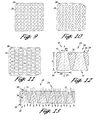
- the induction ducts 28 are disposed about and extend through the air induction plate 18. Referring now to Figures 9-11, there are depicted top views of portions of different embodiments of the present invention, with the air induction ducts 28 having a variety of cross-sectional shapes and configurations.
- the induction ducts 28 may have a circular cross-sectional shape, geometric cross -sectional (e.g., hexagonal, as seen in Figure 11) and even combinations thereof.
- each induction duct 28 has a duct inlet 30, a duct outlet 32 and a duct body 34 interposed between the duct inlet 30 and the duct outlet 32.
- the duct inlets 30 each respectively define an inlet cross-sectional area.
- the inlet cross-sectional area may be used to compute an effective inlet diameter (denoted D1) with the assumption that the area is circular. In the preferred embodiment the effective inlet diameter is less than about 7.6 mm (0.3 inches).
- the duct outlets 32 each respectively define an outlet cross-sectional area.
- The'outlet cross-sectional area may be used to compute an effective outlet diameter (denoted D2) with the assumption that the area is circular.
- the effective outlet diameter (D2) is at least as great as the effective inlet diameter (D1).
- the induction ducts 28 may be formed to expand as airflow passes from the plate front face 24 to the plate back face 26.
- the ratio of the effective inlet diameter (D1) to the effective outlet diameter (D2) may be referred to as the duct expansion ratio.
- the engine 22 emanates engine noise through the air intake 14.
- engine noise has an acoustic signature which is characterized by acoustic amplitudes as various frequencies.
- the duct inlets 30 may be sized and spaced to mitigate selective portions of the engine noise.
- FIG 14 there is depicted an enlarged perspective view of an alternate embodiment of an air induction duct 28 having a variable cross-sectional shape (the duct body being shown in phantom).
- the cross-sectional shape of the duct inlets 30 may be different than the cross-sectional shape of the duct outlet 32. It is contemplated that the sizing, spacing and configuration of the inlets and outlets 30, 32 may be chosen so as to maximize the open area of the back face 26 of the air induction plate 18.
- the present invention mitigates such turbulence by manipulating the air velocity profile within the air intake 14 via the airflow through the induction ducts 28. It is contemplated that airflow passing through such an induction duct 28 expands and in the process is reduced in velocity. As such, the duct expansion ratio impacts the velocity profile of airflow within the air intake. In this regard, the greater the expansion ratio, the greater the uniformity and cohesiveness of the intake air velocity profile. This is because there is a greater amount of open area at the plate back face 26 from which intake airflow is discharged.
- the duct bodies 34 each respectively define a duct body length (L) along a duct longitudinal axis 36.
- the duct body length (L) is at least as long as the effective duct inlet diameter (D1).
- the duct body length (L) is in the range from about the effective duct inlet diameter (D1) to seven (7) times the effective duct inlet diameter (D1).
- the air induction plate 18 is relatively thick and is significantly different from prior art devices which take the form of thin screens, plates or grills. It is contemplated that such a particular sizing of the duct body length (L) (i.e., the thickness of the plate 18) facilitates a laminar channeling of the airflow through the induction duct 28.
- the duct inlets 30 may be provided with a chamfered edge 31.
- the duct inlets 30 each respectively have a chamfer radius (r) of about 20 percent of the associated effective inlet diameter (D1).
- each duct body 34 has a duct longitudinal axis 36.
- the duct longitudinal axis 36 need not be perpendicular to the front and back faces 24, 26, as shown in Figures 12 and 13, but may be at some other angle such as that shown in Figure 15.
- the induction ducts 28 may be similarly aligned with respect to each other and in an angular orientation with respect to the front and back faces 24, 26.
- the induction ducts 28, specifically the longitudinal axes 36 thereof may be variably aligned with respect to the front and back faces 24, 26 at differing portions of the induction plate 18.
- Figure 16 there is depicted an enlarged portion of an exemplary curved induction plate 18.
- the angular orientations of the various longitudinal axes 36 of the induction ducts 28 are variable with respect to the front and back faces 24, 26. Nonetheless, the induction ducts 28 are formed to be similarly aligned with each other and with incident airrflow 44.
- the longitudinal axes 36 may be formed to be substantially co-axial to the anticipated incident airflow adjacent the duct inlets 30.
- FIG 17 there is depicted a cross-sectional view of another embodiment of the induction cover 16 of the present invention. It is contemplated that when in flight, there is a localized airflow 46 which the aircraft 10, to which the induction cover 16 is affixed, is exposed. The direction of the localized airflow 46 is affected by the combination of the incident airflow 44 and the wall surface airflow 48. The incident airflow 44 is primarily due to the direction of flight and other environmental parameters, such as the prevailing wind direction. As mentioned above, the aircraft 10 is provided with an aerodynamic surface curvature 12.
- a wall surface airflow 48 is developed immediately adjacent the aerodynamic surface curvature 12.
- the direction of the wall surface airflow 48 is dominated by the specific features of the aerodynamic surface curvature 12 and may be substantially co-planar therewith.
- the wall surface airflow 48 may be described as a contour airflow adjacent the aerodynamic surface curvature 12 and may be laminar and/or turbulent in nature.
- the localized airflow 46 may be dominated by either of the incident airflow 44 or wall surface airflow 48.
- the intake cover 16 may be disposed and angularly oriented in a variety of positions about the aircraft 10. As such, it is contemplated that the air intake cover 16 may be aligned at a variety of angular orientations with respect to the localized, incident and wall surface airflows 46, 44, 48. It is further contemplated that the respective direction or alignment of the localized, incident and contour airflows may vary as a function of position with respect to the intake cover 16.
- the angular orientations of the various longitudinal axes 36a-f defined by the duct bodies 34a-f of the induction ducts 28a-f are variable with respect to the front and back faces 24, 26.
- the angular orientations of the longitudinal axes 36a-f may be variable with respect to one another.
- the respective longitudinal axes 36 may be formed to be aligned with or formed to be in a general direction of, any of the localized, incident and wall surface airflows 44, 46, 48.
- Such construction and alignment of the duct longitudinal axes 36 are contemplated to facilitate increased airflow into the air intake 14 and pressure recovery associated therewith.
- the longitudinal axis 36f is depicted to be substantially aligned co-axial to the incident airflow 44.
- the wall surface airflow 48 is illustratively shown to be substantially align with the plane of the front face 24 of the induction plate 18. Should it be desirable to align the duct longitudinal axes 36 with the direction of such a wall surface airflow 48, in practice, it is preferable that the duct longitudinal axes 36 may be aligned at between 40° and 50° with respect to the front faces 24 in the direction of the wall surface airflow 48. This is because a lower angular orientation of the longitudinal axes 36 may result in a loss mechanical strength associated with the induction plate 18 thereat. Additionally, it is contemplated that a lower angular orientation of the longitudinal axes 36 results in a relative lengthening of the induction ducts 28 with an associated, and possibly undesirable increase in surface friction thereat.
- the longitudinal axes 36 be aligned no less than 40° to 50° with respect to either the front or back faces 24, 26.
- the air induction plate 18 may be formed of multiple layers.
- the plate 18 is depicted as being formed of first, second and third layers 38, 40, 42.
- the layers 38, 40, 42 may be formed of differing materials.
- the air induction plate 18 or layers thereof may be formed of a graphite composite material, for example.
Landscapes
- Engineering & Computer Science (AREA)
- Chemical & Material Sciences (AREA)
- Combustion & Propulsion (AREA)
- Mechanical Engineering (AREA)
- General Engineering & Computer Science (AREA)
- Aviation & Aerospace Engineering (AREA)
- Testing Of Engines (AREA)
- Structures Of Non-Positive Displacement Pumps (AREA)
Description
Claims (25)
- An aircraft engine air intake cover (16) for use with an air intake (14), the air intake cover comprising:an air induction plate (18) for being disposed across at least a portion of the air intake (14); anda multitude of air induction ducts (28), the induction ducts being disposed about and extending through the air induction plate, each induction duct having a duct inlet (30), a duct outlet (32) and a duct body interposed between the duct inlet and the duct outlet, the duct inlets each respectively defining an effective inlet diameter (D1), the duct bodies each respectively defining a duct body length (L) which is greater than the associated effective duct inlet diameter (D1), the duct outlets each respectively defining an effective outlet diameter (D2) greater than the effective inlet diameter (D1) for increasing the cohesiveness of the air velocity profile within the air intake.
- The air intake cover of Claim 1, wherein the longitudinal axes (36) of the duct bodies are aligned with each other.
- The air intake cover of Claim 1, wherein the longitudinal axes (36) of the duct bodies vary with respect to the angles of opposed front and back faces of the air induction plate (18), such that in use the ducts may be aligned with a localised airflow adjacent their inlets (28).
- The air intake cover of Claim 3, wherein the longitudinal axis (36) of each duct body is inclined at an angle of between 40° and 50° to the front face (24) of the air induction plate (18).
- The air intake cover of any preceding claim, wherein the air intake is defined by an aerodynamic surface curvature, the air induction plate (18) being contiguously formed with the aerodynamic surface curvature (12).
- The air intake cover of any preceding claim, wherein each duct inlet (30) defines an inlet cross-sectional area, each duct outlet defining an outlet cross-sectional area which is greater than the inlet cross-sectional area.
- The air intake cover of any preceding claim, wherein each effective inlet diameter (D1) is less than about 7.6 mm (0.3 inches).
- The air intake cover of any preceding claim, wherein each duct body respectively defines a duct body length (L) which is less than about seven times the associated effective duct inlet (30) diameter.
- The air intake cover of any preceding claim, wherein the duct inlets (30) have a circular cross-sectional shape.
- The air intake cover of any preceding claim, wherein the duct outlets (32) have a geometric cross-sectional shape.
- The air intake cover of any preceding claim, wherein the duct inlets (30) and outlets (32) have different cross-sectional shapes.
- The air intake cover of any preceding claim, wherein the duct inlets (30) are chamfered (31).
- The air intake cover of Claim 12, wherein the duct inlets each respectively have a chamfer radius of about 20 percent of the associated effective inlet diameter (D1).
- The air intake cover of any preceding claim, wherein the air induction plate (18) is formed of a graphite composite material.
- The air intake cover of any preceding claim, wherein the air induction plate (18) is formed of at least two plate layers.
- The air intake cover of Claim 15, wherein the plate layers are formed of different materials.
- The air intake cover of any preceding claim, wherein the air induction plate (18) is dome shaped.
- An aircraft engine comprising:at least one air intake and at least one air intake cover, according to any preceding claim, disposed with its induction plate (18) across at least a portion of the respective air intake (14).
- The aircraft engine of Claim 18, wherein the at least one air intake (14) comprises two air intakes, and the at least one air induction plate (18) comprises two air induction plates.
- The aircraft engine of Claim 18 or 19 wherein the air intake is integrally formed in an engine nacelle (20).
- The aircraft engine of Claim 18 or 19 wherein the air intake is integrally formed in an aircraft wing (15).
- The aircraft engine of any of Claims 18 to 21, wherein the air intake (14,16) is defined by an aerodynamic surface curvature (12).
- The aircraft engine of Claim 22 wherein the aerodynamic surface curvature is disposed across a portion of an engine nacelle (20).
- The aircraft engine of Claim 25 wherein the aerodynamic surface curvature is disposed across a portion of an aircraft wing (15).
- The aircraft engine of any of Claims 18 to 24, wherein engine noise, in use, emanates from within the air intake having acoustic amplitudes greater than a threshold noise amplitude and the effective duct inlet (30) diameters (D1) are less than about the threshold noise amplitude.
Applications Claiming Priority (3)
| Application Number | Priority Date | Filing Date | Title |
|---|---|---|---|
| US09/167,209 US6138950A (en) | 1998-10-06 | 1998-10-06 | Aircraft engine air intake system |
| US167209 | 1998-10-06 | ||
| PCT/US1999/016379 WO2000020272A1 (en) | 1998-10-06 | 1999-07-20 | Aircraft engine air intake system |
Publications (3)
| Publication Number | Publication Date |
|---|---|
| EP1117588A1 EP1117588A1 (en) | 2001-07-25 |
| EP1117588A4 EP1117588A4 (en) | 2002-01-02 |
| EP1117588B1 true EP1117588B1 (en) | 2003-09-24 |
Family
ID=22606404
Family Applications (1)
| Application Number | Title | Priority Date | Filing Date |
|---|---|---|---|
| EP99934150A Expired - Lifetime EP1117588B1 (en) | 1998-10-06 | 1999-07-20 | Aircraft engine air intake system |
Country Status (7)
| Country | Link |
|---|---|
| US (1) | US6138950A (en) |
| EP (1) | EP1117588B1 (en) |
| AU (1) | AU5004399A (en) |
| DE (1) | DE69911630T2 (en) |
| ES (1) | ES2204143T3 (en) |
| IL (1) | IL142403A (en) |
| WO (1) | WO2000020272A1 (en) |
Families Citing this family (42)
| Publication number | Priority date | Publication date | Assignee | Title |
|---|---|---|---|---|
| US8088842B2 (en) | 1999-12-10 | 2012-01-03 | Construction Research & Technology Gmbh | Solubilized defoamers for cementitious compositions |
| US7192462B2 (en) * | 2004-04-14 | 2007-03-20 | Aerospace Filtration Systems, Inc. | Engine air filter and sealing system |
| US7491253B2 (en) * | 2005-05-31 | 2009-02-17 | Aerospace Filtrations Systems, Inc. | Engine intake system with accessible, interchangeable air filters |
| US7721989B2 (en) * | 2006-03-01 | 2010-05-25 | The Boeing Company | Multi-path inlet for aircraft engine |
| US7637455B2 (en) * | 2006-04-12 | 2009-12-29 | The Boeing Company | Inlet distortion and recovery control system |
| US7625415B2 (en) * | 2006-08-23 | 2009-12-01 | Pratt & Whitney Canada Corp. | Strainer for a gas turbine engine |
| US8163050B2 (en) * | 2007-01-22 | 2012-04-24 | Aerospace Filtration Systems, Inc. | Comb for inlet barrier filter system |
| US20090101760A1 (en) * | 2007-03-26 | 2009-04-23 | Maahnchooh Donald Mundingo Ghogomu | Aircraft engine protection unit (A.E.P.U) |
| FR2938824A1 (en) * | 2008-11-26 | 2010-05-28 | Aircelle Sa | NACELLE INTEGRATED ON FLYING WING |
| GB2467567A (en) * | 2009-02-06 | 2010-08-11 | Cyril Staley | Protection of jet engines from bird-strike and foreign object debris |
| US20100284791A1 (en) * | 2009-05-11 | 2010-11-11 | Robert Jesse Flores | Apparatuses, systems, and methods for preventing foreign objects from being ingested into a jet engine |
| US8117820B1 (en) | 2009-05-26 | 2012-02-21 | Briscoe Edward V | Jet engine intake deflector system |
| US7871455B1 (en) | 2009-06-19 | 2011-01-18 | Vintage Capital Group, Llc | Jet engine protection system |
| US20110011055A1 (en) * | 2009-07-17 | 2011-01-20 | Thomas Jay Troy | Jet engine air intake guard |
| US8052083B1 (en) * | 2009-09-17 | 2011-11-08 | John Patrick Moran | Bird deflector and air replacement system technical field |
| US8256706B1 (en) * | 2009-10-08 | 2012-09-04 | The Boeing Company | Integrated hypersonic inlet design |
| US7803204B1 (en) * | 2009-10-19 | 2010-09-28 | Mladinich Julius C | Foreign object deflector for jet engine |
| US20110146294A1 (en) * | 2009-12-22 | 2011-06-23 | Rubin Townsend | Airplane engine deflector systems |
| USD621852S1 (en) * | 2010-01-26 | 2010-08-17 | John Zunik | Aircraft engine safety shield |
| US8365591B2 (en) | 2010-11-15 | 2013-02-05 | Rosemount Aerospace Inc. | Static port apparatus |
| GB201108951D0 (en) | 2011-05-24 | 2011-10-05 | Bae Systems Plc | Air vehicles |
| US8419815B1 (en) * | 2011-10-27 | 2013-04-16 | John Patrick Moran | Bird deflector and air replacement system |
| GB201121887D0 (en) * | 2011-12-20 | 2012-02-01 | Rolls Royce Plc | Intake liner for a gas turbine engine |
| US9067679B2 (en) | 2011-12-30 | 2015-06-30 | Aerospace Filtration Systems, Inc. | Heated screen for air intake of aircraft engines |
| US8657895B2 (en) | 2012-05-02 | 2014-02-25 | Michael J. Kline | Jet engine deflector |
| US8968437B2 (en) | 2012-05-02 | 2015-03-03 | Michael J Kline | Jet engine with deflector |
| US8777154B2 (en) * | 2012-07-09 | 2014-07-15 | United Technologies Corporation | Apparatus and method for preventing gas turbine engine freezing |
| CN103569369A (en) * | 2012-07-27 | 2014-02-12 | 刘彦癸 | Aircraft engine bird protection cover |
| DE102013001617A1 (en) * | 2013-01-28 | 2014-07-31 | Hans-Jürgen Luckow | Engine with protective device |
| US9145214B2 (en) * | 2013-10-25 | 2015-09-29 | Honeywell International Inc. | Auxiliary power unit inlet door having openings formed therein |
| EP2995556B1 (en) * | 2014-09-12 | 2018-11-07 | AIRBUS HELICOPTERS DEUTSCHLAND GmbH | An aircraft with an air intake for an air breathing propulsion engine |
| KR102358885B1 (en) * | 2015-02-12 | 2022-02-08 | 하이드로키네틱 에너지 코퍼레이션 | Hydro/hydrodynamic turbines and methods for making and using them |
| US11022088B2 (en) * | 2015-02-12 | 2021-06-01 | Hydrokinetic Energy Corp | Accelerated and-or redirected flow-inducing and-or low pressure field or area-inducing arrangement, their use with turbine-like devices and method for using same |
| CN107614379A (en) | 2015-05-25 | 2018-01-19 | 多特瑞尔技术有限公司 | Shield for aircraft |
| JP6768391B2 (en) * | 2016-07-26 | 2020-10-14 | 三菱重工業株式会社 | Aperture cover and aircraft |
| US10556701B2 (en) * | 2017-04-14 | 2020-02-11 | Rohr, Inc. | Bird-strike energy absorbing net |
| AU2018306554A1 (en) | 2017-07-24 | 2020-02-20 | Dotterel Technologies Limited | Shroud |
| RU2682700C2 (en) * | 2017-07-28 | 2019-03-20 | федеральное государственное бюджетное образовательное учреждение высшего образования "Алтайский государственный университет" | Highly maneuverable aircraft |
| WO2019221613A1 (en) | 2018-05-16 | 2019-11-21 | Dotterel Technologies Limited | Systems and methods for audio capture |
| KR102307265B1 (en) * | 2019-08-05 | 2021-09-30 | 김응기 | Agricultural drone |
| CA3219488A1 (en) * | 2021-06-03 | 2022-12-08 | Ptp Turbo Solutions, Llc. | Systems and methods associated with a removable inlet shield |
| CN114715417A (en) * | 2022-04-18 | 2022-07-08 | 中国商用飞机有限责任公司北京民用飞机技术研究中心 | Aircraft air inlet device, system and non-supercharged cabin |
Family Cites Families (28)
| Publication number | Priority date | Publication date | Assignee | Title |
|---|---|---|---|---|
| US2598603A (en) * | 1949-01-22 | 1952-05-27 | Joseph P Richtarsic | Ceramic spark arrester |
| US2944631A (en) * | 1956-01-06 | 1960-07-12 | Rolls Royce | Retractable guards for air intakes |
| US2846023A (en) * | 1956-04-19 | 1958-08-05 | Gen Dynamics Corp | Protective device for jet engines |
| US2931460A (en) * | 1957-12-12 | 1960-04-05 | Orenda Engines Ltd | Debris guard |
| US3121545A (en) * | 1962-01-10 | 1964-02-18 | John J Moss | Rotary deflector for aircraft engine intakes |
| US3196598A (en) * | 1962-10-31 | 1965-07-27 | Walter T Olson | Inlet deflector for jet engines |
| US3286459A (en) * | 1963-12-31 | 1966-11-22 | Gen Motors Corp | Turbine inlet screen assembly |
| GB1137479A (en) * | 1966-02-28 | 1968-12-18 | Mini Of Technology | Foreign body guards for aircraft |
| US3735587A (en) * | 1971-05-06 | 1973-05-29 | Gen Motors Corp | Engine exhaust turbine inlet screen |
| US3778983A (en) * | 1972-08-30 | 1973-12-18 | Avco Corp | Integral multichannel separator |
| US3871844A (en) * | 1973-09-28 | 1975-03-18 | Sr Frank F Calvin | Screen apparatus for air inlet |
| GB1512645A (en) * | 1974-08-06 | 1978-06-01 | Hawker Siddeley Aviation Ltd | Aircraft |
| GB1544202A (en) * | 1975-05-23 | 1979-04-11 | Lucas Industries Ltd | Filter |
| US4149689A (en) * | 1976-08-18 | 1979-04-17 | Mcdonald John | Protective screen for jet-engine intake |
| US4077739A (en) * | 1976-12-20 | 1978-03-07 | General Motors Corporation | Engine turbocharger turbine inlet screen |
| GB2140090B (en) * | 1982-12-23 | 1986-10-01 | Rolls Royce | Air intakes of helicopter mounted gas turbine engines |
| US4738416A (en) * | 1986-09-26 | 1988-04-19 | Quiet Nacelle Corporation | Nacelle anti-icing system |
| US4928480A (en) * | 1988-03-04 | 1990-05-29 | General Electric Company | Separator having multiple particle extraction passageways |
| US5106397A (en) * | 1990-12-26 | 1992-04-21 | Ford Motor Company | Air cleaner/noise silencer assembly |
| US5366177A (en) * | 1992-10-05 | 1994-11-22 | Rockwell International Corporation | Laminar flow control apparatus for aerodynamic surfaces |
| US5522566A (en) * | 1993-02-02 | 1996-06-04 | The Boeing Company | Fighter aircraft having low aerodynamic drag and low radar signature configuration |
| US5398410A (en) * | 1993-03-19 | 1995-03-21 | Mcdonnell Douglas Corporation | Method of making a superplastically formed structure having a perforated skin |
| US5411224A (en) * | 1993-04-08 | 1995-05-02 | Dearman; Raymond M. | Guard for jet engine |
| US5590854A (en) * | 1994-11-02 | 1997-01-07 | Shatz; Solomon | Movable sheet for laminar flow and deicing |
| US5662292A (en) * | 1995-05-03 | 1997-09-02 | Greene; Andrew T. | Helicopter engine filter system |
| US5772156A (en) * | 1995-11-30 | 1998-06-30 | The Boeing Company | Aircraft boundary layer control system with discharge transpiration panel |
| US5779169A (en) * | 1995-12-15 | 1998-07-14 | The Boeing Company | Aircraft engine inlet hot gas and foreign object ingestion reduction and pitch control system |
| US5721402A (en) * | 1996-09-09 | 1998-02-24 | Northrop Grumman Corporation | Noise suppression system for a jet engine |
-
1998
- 1998-10-06 US US09/167,209 patent/US6138950A/en not_active Expired - Lifetime
-
1999
- 1999-07-20 ES ES99934150T patent/ES2204143T3/en not_active Expired - Lifetime
- 1999-07-20 AU AU50043/99A patent/AU5004399A/en not_active Abandoned
- 1999-07-20 IL IL14240399A patent/IL142403A/en not_active IP Right Cessation
- 1999-07-20 EP EP99934150A patent/EP1117588B1/en not_active Expired - Lifetime
- 1999-07-20 WO PCT/US1999/016379 patent/WO2000020272A1/en not_active Ceased
- 1999-07-20 DE DE69911630T patent/DE69911630T2/en not_active Expired - Fee Related
Also Published As
| Publication number | Publication date |
|---|---|
| ES2204143T3 (en) | 2004-04-16 |
| EP1117588A4 (en) | 2002-01-02 |
| EP1117588A1 (en) | 2001-07-25 |
| US6138950A (en) | 2000-10-31 |
| IL142403A (en) | 2004-03-28 |
| DE69911630T2 (en) | 2004-07-08 |
| WO2000020272A1 (en) | 2000-04-13 |
| AU5004399A (en) | 2000-04-26 |
| DE69911630D1 (en) | 2003-10-30 |
| IL142403A0 (en) | 2002-03-10 |
Similar Documents
| Publication | Publication Date | Title |
|---|---|---|
| US6138950A (en) | Aircraft engine air intake system | |
| US5743488A (en) | Aerodynamic low drag structure | |
| US8210482B2 (en) | Prismatic-shaped vortex generators | |
| CN108290636B (en) | Turbine engine propelled aircraft with acoustic panels | |
| CA1257971A (en) | Gas turbine engine nacelle | |
| EP2084061B1 (en) | Supersonic aircraft jet engine | |
| EP0273851B1 (en) | Gas turbine engine airfoil | |
| US4813635A (en) | Projectile with reduced base drag | |
| US5915403A (en) | Biplanar scarfed nacelle inlet | |
| EP3109153B1 (en) | Swept gradient boundary layer diverter | |
| US20100180574A1 (en) | Gas turbine engine | |
| WO2008017567A1 (en) | Air inlet for a jet engine | |
| EP0940338B1 (en) | Gearbox breather outlet | |
| EP1031510A2 (en) | Turbo fan engine nacelle exhaust system with concave primary nozzle plug | |
| US20260042533A1 (en) | Streamline airframe with boundary ingestion fluidic propulsive elements | |
| US7735776B2 (en) | Air inlet for a turbofan engine | |
| KR20200122307A (en) | Device for reducing drag force of transverse duct outlet flow | |
| RU2670664C1 (en) | Asymmetrical air-scoop for three flow engine of faster-than-sound aircraft | |
| GB2296306A (en) | Reducing drag by boundary layer control | |
| JPH0281798A (en) | Two-dimensional symmetric supersonic hypersonic air intake of combustion air of aero-engine | |
| US12595039B2 (en) | Air directing arrangement for controlling airflow at an outlet | |
| CN121626398A (en) | wing-body blended aircraft integrating a full-grid air intake and exhaust system with a boundary layer intake propulsion system |
Legal Events
| Date | Code | Title | Description |
|---|---|---|---|
| PUAI | Public reference made under article 153(3) epc to a published international application that has entered the european phase |
Free format text: ORIGINAL CODE: 0009012 |
|
| 17P | Request for examination filed |
Effective date: 20010501 |
|
| AK | Designated contracting states |
Kind code of ref document: A1 Designated state(s): AT BE CH CY DE DK ES FI FR GB GR IE IT LI LU MC NL PT SE |
|
| AX | Request for extension of the european patent |
Free format text: AL;LT;LV;MK;RO;SI |
|
| RIN1 | Information on inventor provided before grant (corrected) |
Inventor name: BOCCADORO, CHARLES Inventor name: SHULTZ, DOUGLAS, ELLWOOD Inventor name: PHILHOWER, JEFFRY, SCOTT Inventor name: GEORGES, MARTIN, JAMES Inventor name: LEGGETT, DOUGLAS, WILLIAM Inventor name: RIHN, DANIEL, R. Inventor name: LIU, YU, PING Inventor name: WAINFAN, BARNABY, SAM |
|
| A4 | Supplementary search report drawn up and despatched |
Effective date: 20011115 |
|
| AK | Designated contracting states |
Kind code of ref document: A4 Designated state(s): AT BE CH CY DE DK ES FI FR GB GR IE IT LI LU MC NL PT SE |
|
| RIC1 | Information provided on ipc code assigned before grant |
Free format text: 7B 64D 33/02 A, 7F 02C 7/05 B, 7F 02C 7/055 B |
|
| 17Q | First examination report despatched |
Effective date: 20020611 |
|
| GRAH | Despatch of communication of intention to grant a patent |
Free format text: ORIGINAL CODE: EPIDOS IGRA |
|
| GRAS | Grant fee paid |
Free format text: ORIGINAL CODE: EPIDOSNIGR3 |
|
| GRAA | (expected) grant |
Free format text: ORIGINAL CODE: 0009210 |
|
| AK | Designated contracting states |
Kind code of ref document: B1 Designated state(s): DE ES FR GB IT SE |
|
| REG | Reference to a national code |
Ref country code: GB Ref legal event code: FG4D |
|
| REF | Corresponds to: |
Ref document number: 69911630 Country of ref document: DE Date of ref document: 20031030 Kind code of ref document: P |
|
| REG | Reference to a national code |
Ref country code: SE Ref legal event code: TRGR |
|
| REG | Reference to a national code |
Ref country code: ES Ref legal event code: FG2A Ref document number: 2204143 Country of ref document: ES Kind code of ref document: T3 |
|
| ET | Fr: translation filed | ||
| PLBE | No opposition filed within time limit |
Free format text: ORIGINAL CODE: 0009261 |
|
| STAA | Information on the status of an ep patent application or granted ep patent |
Free format text: STATUS: NO OPPOSITION FILED WITHIN TIME LIMIT |
|
| 26N | No opposition filed |
Effective date: 20040625 |
|
| PGFP | Annual fee paid to national office [announced via postgrant information from national office to epo] |
Ref country code: FR Payment date: 20060717 Year of fee payment: 8 |
|
| PGFP | Annual fee paid to national office [announced via postgrant information from national office to epo] |
Ref country code: GB Payment date: 20060726 Year of fee payment: 8 Ref country code: ES Payment date: 20060726 Year of fee payment: 8 |
|
| PGFP | Annual fee paid to national office [announced via postgrant information from national office to epo] |
Ref country code: DE Payment date: 20060831 Year of fee payment: 8 |
|
| PGFP | Annual fee paid to national office [announced via postgrant information from national office to epo] |
Ref country code: SE Payment date: 20060727 Year of fee payment: 8 Ref country code: IT Payment date: 20070726 Year of fee payment: 9 |
|
| EUG | Se: european patent has lapsed | ||
| GBPC | Gb: european patent ceased through non-payment of renewal fee |
Effective date: 20070720 |
|
| PG25 | Lapsed in a contracting state [announced via postgrant information from national office to epo] |
Ref country code: SE Free format text: LAPSE BECAUSE OF NON-PAYMENT OF DUE FEES Effective date: 20070721 Ref country code: DE Free format text: LAPSE BECAUSE OF NON-PAYMENT OF DUE FEES Effective date: 20080201 |
|
| PG25 | Lapsed in a contracting state [announced via postgrant information from national office to epo] |
Ref country code: GB Free format text: LAPSE BECAUSE OF NON-PAYMENT OF DUE FEES Effective date: 20070720 |
|
| REG | Reference to a national code |
Ref country code: FR Ref legal event code: ST Effective date: 20080331 |
|
| PG25 | Lapsed in a contracting state [announced via postgrant information from national office to epo] |
Ref country code: FR Free format text: LAPSE BECAUSE OF NON-PAYMENT OF DUE FEES Effective date: 20070731 |
|
| REG | Reference to a national code |
Ref country code: ES Ref legal event code: FD2A Effective date: 20070721 |
|
| PG25 | Lapsed in a contracting state [announced via postgrant information from national office to epo] |
Ref country code: ES Free format text: LAPSE BECAUSE OF NON-PAYMENT OF DUE FEES Effective date: 20070721 |
|
| PG25 | Lapsed in a contracting state [announced via postgrant information from national office to epo] |
Ref country code: IT Free format text: LAPSE BECAUSE OF NON-PAYMENT OF DUE FEES Effective date: 20080720 |