EP1117278A2 - Verfahren und Vorrichtung zur Verlängerung des verbrauchbaren Lebens eines Plasmalichtbogens - Google Patents
Verfahren und Vorrichtung zur Verlängerung des verbrauchbaren Lebens eines Plasmalichtbogens Download PDFInfo
- Publication number
- EP1117278A2 EP1117278A2 EP01300109A EP01300109A EP1117278A2 EP 1117278 A2 EP1117278 A2 EP 1117278A2 EP 01300109 A EP01300109 A EP 01300109A EP 01300109 A EP01300109 A EP 01300109A EP 1117278 A2 EP1117278 A2 EP 1117278A2
- Authority
- EP
- European Patent Office
- Prior art keywords
- oxidizing gas
- time
- nozzle
- plasma arc
- electrode
- Prior art date
- Legal status (The legal status is an assumption and is not a legal conclusion. Google has not performed a legal analysis and makes no representation as to the accuracy of the status listed.)
- Withdrawn
Links
Images

Classifications
-
- B—PERFORMING OPERATIONS; TRANSPORTING
- B23—MACHINE TOOLS; METAL-WORKING NOT OTHERWISE PROVIDED FOR
- B23K—SOLDERING OR UNSOLDERING; WELDING; CLADDING OR PLATING BY SOLDERING OR WELDING; CUTTING BY APPLYING HEAT LOCALLY, e.g. FLAME CUTTING; WORKING BY LASER BEAM
- B23K10/00—Welding or cutting by means of a plasma
-
- H—ELECTRICITY
- H05—ELECTRIC TECHNIQUES NOT OTHERWISE PROVIDED FOR
- H05H—PLASMA TECHNIQUE; PRODUCTION OF ACCELERATED ELECTRICALLY-CHARGED PARTICLES OR OF NEUTRONS; PRODUCTION OR ACCELERATION OF NEUTRAL MOLECULAR OR ATOMIC BEAMS
- H05H1/00—Generating plasma; Handling plasma
- H05H1/24—Generating plasma
- H05H1/26—Plasma torches
- H05H1/32—Plasma torches using an arc
- H05H1/34—Details, e.g. electrodes, nozzles
- H05H1/36—Circuit arrangements
-
- H—ELECTRICITY
- H05—ELECTRIC TECHNIQUES NOT OTHERWISE PROVIDED FOR
- H05H—PLASMA TECHNIQUE; PRODUCTION OF ACCELERATED ELECTRICALLY-CHARGED PARTICLES OR OF NEUTRONS; PRODUCTION OR ACCELERATION OF NEUTRAL MOLECULAR OR ATOMIC BEAMS
- H05H1/00—Generating plasma; Handling plasma
- H05H1/24—Generating plasma
- H05H1/26—Plasma torches
- H05H1/32—Plasma torches using an arc
- H05H1/34—Details, e.g. electrodes, nozzles
- H05H1/3442—Cathodes with inserted tip
-
- H—ELECTRICITY
- H05—ELECTRIC TECHNIQUES NOT OTHERWISE PROVIDED FOR
- H05H—PLASMA TECHNIQUE; PRODUCTION OF ACCELERATED ELECTRICALLY-CHARGED PARTICLES OR OF NEUTRONS; PRODUCTION OR ACCELERATION OF NEUTRAL MOLECULAR OR ATOMIC BEAMS
- H05H1/00—Generating plasma; Handling plasma
- H05H1/24—Generating plasma
- H05H1/26—Plasma torches
- H05H1/32—Plasma torches using an arc
- H05H1/34—Details, e.g. electrodes, nozzles
- H05H1/3452—Supplementary electrodes between cathode and anode, e.g. cascade
Definitions
- the present invention relates to plasma arc torches and, more particularly, to a method and plasma arc torch apparatus for stopping a cutting operation of the plasma arc torch such that the life of the torch consumable is improved.
- Plasma arc torches have a wide variety of applications for the working of metals, including cutting, welding, and annealing.
- Such torches usually include an electrode, also known as a consumable, for supporting an arc that extends from the electrode to a workpiece.
- a plasma gas such as an oxidizing gas is typically directed through a nozzle assembly to a plasma chamber between the electrode and the nozzle such that the plasma gas is operable to impinge on the workpiece with the gas surrounding the arc in a swirling fashion.
- the electrode includes an emissive insert which emits electrons upon an electrical potential being applied between the electrode and the workpiece.
- the torch may be turned off through a stop program which extinguishes the arc.
- oxidizing and non-oxidizing gases may be selectively introduced into the plasma chamber via a pair of actuatable valves.
- One or more gas feed lines direct the oxidizing or non-oxidizing gas from the solenoid valves to the plasma chamber at the tip of the torch.
- the actuatable valves may be opened and closed to exchange the oxidizing gas for the non-oxidizing gas at the end of the cutting process.
- a common method for shutting down the torch following a plasma arc cutting process typically includes the following simultaneous operations: switching off the power supply to the electrode; switching off the oxidizing gas, such as oxygen; and switching on a non-oxidizing gas, such as nitrogen, to flush the oxidizing gas from the torch.
- the plasma arc extinguishes before the non-oxidizing gas completely purges the undesirable oxidizing gas from the plasma chamber of the torch, such that the arc extinguishes in a non-inert environment in the vicinity of the front emitting face of the electrode.
- This time delay or lag is due to the volume of gas contained within the tubing and passageways extending between the valves and the plasma chamber adjacent the electrode and nozzle assembly.
- All of the undesirable oxidizing gas to be purged must be ejected through the nozzle of the torch, which is a time consuming process dependent on the size of the nozzle orifice, the length and volume of the gas tubing, gas passageways and plasma chamber, the rate of flow of the non-oxidizing gas into the tubing, passageways and plasma chamber, and the rate of flow of the oxidizing gas through the nozzle.
- oxides form on the outer surface of the electrode. Although the formed oxides are typically burned off when the arc is restarted, the repeated formation and burning off of oxides on the electrode contributes to accelerated consumable wear and poor starting performance.
- Another method for stopping the cutting operation of the plasma arc torch includes venting the plasma chamber to atmosphere while reducing or cutting the flow of oxidizing gas to the plasma chamber, such that the oxidizing gas ejects both through the nozzle of the torch and through the vent to atmosphere to facilitate a more rapid change in the gas flow pattern in the plasma chamber.
- a residual flow rate of the oxidizing gas remains in the plasma chamber to maintain the stability of the arc in order to prevent damage to the electrode.
- the arc extinguishes in a non-inert environment which causes the formation of oxides as described above.
- a stopping process for plasma arc torches of the type having a metallic electrode and nozzle assembly positioned adjacent a discharge end of the electrode and defining a plasma chamber between the electrode and the nozzle, wherein the process minimizes the oxidation of the electrode and thereby extends the life of the electrode.
- a flow of an oxidizing gas such as oxygen
- an oxidizing gas is first directed by a valve and passageway through the plasma chamber and nozzle of the plasma arc torch.
- Electrical current is supplied by a power source and directed through the electrode to form a plasma arc which extends between the electrode and a workpiece during a cutting operation.
- the electrical current is stepped down at a time F for extinguishing the plasma arc.
- the flow of oxidizing gas is switched off by a valve at a predetermined time interval before time F , and a flow of non-oxidizing gas, such as nitrogen, is switched on by a valve such that no later than at time F the non-oxidizing gas has substantially completely purged the oxidizing gas from the plasma chamber.
- the predetermined time interval is dependent upon several constants measurable for a given torch, such as the size of the nozzle, the volume of the gas passageways and plasma chamber, the rate of flow of the non-oxidizing gas into the passageways and plasma chamber, and the rate of flow of the oxidizing gas through the nozzle.
- a plasma arc torch is also provided by the present invention.
- the torch includes a nozzle defining a gas flow path therethrough and an electrode positioned adjacent the nozzle.
- the electrode is capable of supporting an electrical arc which may be supplied by an electrical power supply operably connected to the electrode.
- the torch also includes pairs of valves and passageways for directing flows of oxidizing and non-oxidizing gas through the nozzle.
- a processor such as a microprocessor, is operatively coupled to the valves and power supply.
- the processor is operable to close the valve controlling the oxidizing gas flow and to open the valve controlling the non-oxidizing gas flow at predetermined time intervals before the plasma arc is extinguished, such that at a time no later than when the arc is extinguished the non-oxidizing gas has substantially completely purged the oxidizing gas from the nozzle creating an inert environment adjacent the electrode.
- the arc extinguishes in an inert environment is operable to close the valve controlling the oxidizing gas flow and to open the valve controlling the non-oxidizing gas flow at predetermined time intervals before the plasma arc is extinguished, such that at a time no later than when the arc is extinguished the non-oxidizing gas has substantially completely purged the oxidizing gas from the nozzle creating an inert environment adjacent the electrode.
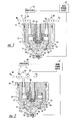
- the plasma arc torch 10 includes a nozzle assembly 11 and a tubular electrode 12.
- a plasma chamber 41 is defined by the torch 10 between the electrode 12 and the nozzle assembly 11 .
- the electrode 12 is preferably made of copper or a copper alloy, and includes a cup-shaped member or holder 14 attached thereto.
- the cup-shaped member or holder 14 is of a tubular construction and includes a lower front end and an upper rear end.
- a transverse end wall 16 closes the front end of the holder 14 and defines an outer front face 17 of the electrode 12 .
- a cavity 18 is defined by the electrode 12 in the front face 17 of the end wall 16 and extends toward the upper rear end of the holder 14 along the longitudinal axis of the torch 10 .
- An insert assembly 20 is mounted in the cavity 18 and comprises a generally cylindrical emissive insert 21 which is disposed coaxially along the longitudinal axis of the torch 10 .
- the emissive insert 21 typically comprises a metallic material which has a relatively low work function so that it is adapted to readily emit electrons upon application of an electrical potential. Suitable examples of such materials are hafnium, zirconium, tungsten, and alloys thereof.
- the electrode 12 is mounted in a plasma arc torch body (not shown) which includes a plurality of gas passageways 26, 27 .
- a liquid passageway (not shown) leads through the torch body to assist in cooling the torch 10 during operation.
- the gas passageways 26, 27 receive gases from suitable sources (not shown) which, in accordance with the present invention, include a source of a non-oxidizing gas, preferably nitrogen (N 2 ), and a source of an oxidizing gas, preferably oxygen (O 2 ). Alternatively, air may be used as the oxidizing gas.
- suitable sources not shown
- suitable sources include a source of a non-oxidizing gas, preferably nitrogen (N 2 ), and a source of an oxidizing gas, preferably oxygen (O 2 ).
- air may be used as the oxidizing gas.
- the gases are separately supplied to the passages 26, 27 through valves 70, 71 .
- the valves may include electrically operable actuators 82, 84 , such as solenoids, which open and close the valves 70, 71 to introduce each gas from the respective source to the appropriate gas passageway.
- the first gas passageway 26 is dedicated exclusively to introduction of the non-oxidizing gas N 2 into the plasma chamber 41
- the second gas passageway 27 is dedicated exclusively to introduction of the oxidizing gas O 2 into the plasma chamber.
- the same gas passageway may be used to introduce both the non-oxidizing and oxidizing gases into the plasma chamber 41.
- the baffle 40 has tangentially skewed holes such that each gas is introduced into the plasma chamber 41 with a swirling flow pattern.
- Each gas then flows from the plasma chamber 41 through the nozzle assembly 11 and is directed toward a workpiece W.
- the electrode 12 holds the ceramic gas baffle 40 in place, along with a high temperature insulating member 44 which may be made of plastic or other non-conductive material.
- the member 44 electrically insulates the nozzle assembly 11 from the electrode 12.
- the nozzle assembly 11 comprises an upper nozzle member 45 and a lower nozzle member 46 .
- the upper and lower members 45, 46 include first and second arc constricting nozzle bores 42, 43 , respectively.
- the upper and lower nozzle members 45, 46 may be metal; however, a ceramic material such as alumina may be used for the lower nozzle member 46 .
- the lower nozzle member 46 is separated from the upper nozzle member 45 by an insulative spacer element and water swirl ring (not shown).
- the bore 42 of the upper nozzle member 45 is in axial alignment with the longitudinal axis of the torch electrode 12 .
- the bore 42 is preferably cylindrical and has a chamfered upper end adjacent the plasma chamber 41 , with a chamfer angle of about 45°.
- the lower nozzle member 46 comprises a cylindrical body portion 52 which defines a forward (or lower) end portion and a rearward (or upper) end portion.
- the bore 43 extends coaxially through the body portion 52 of the lower nozzle member 46.
- An annular mounting flange 53 is positioned on the rearward end portion of the nozzle member 46 , and a frustro-conical surface 54 is formed on the exterior of the forward end portion of the lower nozzle member 46 so as to be coaxial with the second bore 43.
- the annular flange 53 is supported from below by an inwardly directed flange 55 at the lower end of the cup 56.
- the cup 56 is detachably mounted by interconnecting threads of the outer housing member (not shown). Also, a gasket 57 is disposed between the two flanges 53, 55.
- the arc constricting bore 43 in the lower nozzle member 46 is cylindrical, and it is maintained in axial alignment with the arc constricting bore 42 of the upper nozzle member 45 by a centering sleeve 60 of any suitable plastic material.
- the centering sleeve 60 has a lip at the upper end thereof which is detachably locked into an annular notch in the upper nozzle member 45 .
- the centering sleeve 60 extends from the upper nozzle member 45 and is in biased engagement against the lower nozzle member 46 .
- a main power supply 67 is connected to the electrode 12 and to the workpiece W in a series circuit relationship.
- the torch also includes a processor 66 operatively coupled with the valves 70, 71 .
- the processor 66 acts to open and close the valves 70, 71 such that the non-oxidizing and oxidizing gases are introduced into the gas passageways 26, 27.
- the processor 66 is capable of at least issuing an arc current step-down command to the power supply 67 for extinguishing the arc, closing the valve 70 to stop the flow of the oxidizing gas, and opening the valve 71 so as to initiate the flow of the non-oxidizing gas.
- the processor 66 is capable of issuing a command to switch off the power supply 67 at a predetermined time interval before the actual end of a cutting operation.
- the predetermined time interval takes into account the extinguish delay time that inevitably occurs between issuance of the arc current step-down command and the actual extinguishment of the arc.
- delay will vary depending on various factors but is generally a constant for a given torch system and can be experimentally determined.
- the delay time is extinguished substantially concurrently with the end of a desired cutting operation. This method is more fully described in U.S. Patent No. 5,893,986, currently assigned to the assignee of the present invention and hereby incorporated by reference.
- the processor 66 also controls the opening and closing of the valves 70, 71 such that the non-oxidizing gas has substantially completely purged the oxidizing gas from the torch 10 by the time the arc extinguishes, creating an inert environment adjacent the electrode, whereby the arc extinguishes in the inert environment.
- FIG. 3 a timing graph is shown depicting operation of the plasma arc torch in accordance with the present invention.
- Arc current, oxidizing gas pressure, non-oxidizing gas pressure, and the type of gas present in the torch are all plotted versus time.
- the top line represents the arc current to the electrode.
- the second and third lines from the top depict the non-oxidizing and oxidizing gas pressures in the torch 10 , respectively.
- the bottommost line depicts the type of gas present in the torch 10 at a given time, specifically showing when one gas has substantially completely replaced the other gas in the nozzle 11 of the torch 10.
- the process start is initiated by opening valve 71 , at time A so that a supply of non-oxidizing gas, such as nitrogen, passes through the valve and the passage 26 of the torch and enters the plasma chamber 41 from which the gas is discharged through the nozzle.
- a pilot arc is established between the electrode 12 and the nozzle 11 .
- the flow of oxidizing gas, such as oxygen is commenced by opening valve 70 at time B.
- valve 71 is closed concurrently with the opening of valve 70, which allows the oxidizing gas to purge the non-oxidizing gas from the plasma chamber by time C a short time after time B.
- valve 71 is closed a short time after valve 70 is opened.
- the power supply 67 begins supplying a full cutting arc current to the electrode, such that by time C the arc is transferred from the nozzle 11 and on to the a workpiece W through the arc constricting bores 42, 43 of the upper and lower nozzle members 45, 46.
- the transferred arc and the oxidizing gas create a plasma gas flow from the electrode 12 through the nozzle assembly 11 and to the workpiece W.
- the torch is in full cutting operation beginning at time C. The torch is then moved along a predetermined cutting path.
- the electrical current from the power supply 67 is stepped down to extinguish the plasma arc.
- the term "stepped down" is defined as cutting the electrical current in one step or, alternatively, gradually decreasing the electrical current.
- the current may be stepped down concurrently with the torch being brought to a stop.
- the current may be stepped down at a time before time F , such as at a time E , such that the arc extinguishes substantially concurrently with the halting of the torch, as previously noted and as detailed in U.S. Patent No. 5,893,986.
- the flow of oxidizing gas is switched off by closing the valve 70 at a time D which is a determinable time interval before time F , and a flow of non-oxidizing gas is switched on by opening the valve 71 such that no later than at time F when the arc extinguishes, the non-oxidizing gas has substantially completely purged the oxidizing gas from the plasma chamber.
- the time interval between time D and time F is dependent on several factors, such as the size of the nozzle 14 , the fixed volume of the gas passageways 26, 27 and plasma chamber 41 , the rate of flow of the non-oxidizing gas, and the rate of flow of the oxidizing gas.
- the determinable time interval D-F tends to be a constant for a given torch system, and can be experimentally determined.
- the time interval D-F is accounted for in programming the processor 66 so that the valves 70, 71 may be controllably opened and closed by the processor 66 according to the present invention, such that an inert environment is present in the torch 10 when the arc is extinguished.
- the stopping process of the present invention offers several advantages. Extinguishing the plasma arc in an inert environment greatly reduces or substantially eliminates the formation of oxides on the outer surface of the consumable and electrode which can lead to increased wear of the electrode and poor starting performance. In torches which use a copper nozzle, oxidation and erosion of the copper nozzle also are greatly reduced. The process in accordance with the present invention permits a greater number of start-stop cycles between electrode and/or nozzle replacements because the electrode and nozzle longevity are extended.
Landscapes
- Engineering & Computer Science (AREA)
- Physics & Mathematics (AREA)
- Plasma & Fusion (AREA)
- Spectroscopy & Molecular Physics (AREA)
- Mechanical Engineering (AREA)
- Plasma Technology (AREA)
- Arc Welding In General (AREA)
- Arc Welding Control (AREA)
Applications Claiming Priority (2)
| Application Number | Priority Date | Filing Date | Title |
|---|---|---|---|
| US09/482,781 US6232574B1 (en) | 2000-01-13 | 2000-01-13 | Method and apparatus for improving plasma ARC consumable life |
| US482781 | 2000-01-13 |
Publications (2)
| Publication Number | Publication Date |
|---|---|
| EP1117278A2 true EP1117278A2 (de) | 2001-07-18 |
| EP1117278A3 EP1117278A3 (de) | 2003-11-05 |
Family
ID=23917432
Family Applications (1)
| Application Number | Title | Priority Date | Filing Date |
|---|---|---|---|
| EP01300109A Withdrawn EP1117278A3 (de) | 2000-01-13 | 2001-01-08 | Verfahren und Vorrichtung zur Verlängerung des verbrauchbaren Lebens eines Plasmalichtbogens |
Country Status (5)
| Country | Link |
|---|---|
| US (1) | US6232574B1 (de) |
| EP (1) | EP1117278A3 (de) |
| JP (1) | JP2001239370A (de) |
| AU (1) | AU754048B2 (de) |
| CA (1) | CA2330069C (de) |
Families Citing this family (14)
| Publication number | Priority date | Publication date | Assignee | Title |
|---|---|---|---|---|
| US6777638B2 (en) * | 2002-11-14 | 2004-08-17 | The Esab Group, Inc. | Plasma arc torch and method of operation for reduced erosion of electrode and nozzle |
| US7750265B2 (en) * | 2004-11-24 | 2010-07-06 | Vladimir Belashchenko | Multi-electrode plasma system and method for thermal spraying |
| US20070045241A1 (en) * | 2005-08-29 | 2007-03-01 | Schneider Joseph C | Contact start plasma torch and method of operation |
| US8338739B2 (en) | 2008-12-22 | 2012-12-25 | Hypertherm, Inc. | Method and apparatus for cutting high quality internal features and contours |
| US8541711B2 (en) | 2009-02-20 | 2013-09-24 | Hypertherm, Inc. | Internal part feature cutting method and apparatus |
| CN101952076B (zh) * | 2008-12-22 | 2014-12-24 | 海别得公司 | 用于切割高质量内部结构和轮廓的方法和装置 |
| US8354609B2 (en) * | 2008-12-22 | 2013-01-15 | Hypertherm, Inc. | High quality hole cutting using variable shield gas compositions |
| FR2943568A1 (fr) * | 2009-03-25 | 2010-10-01 | Air Liquide | Procede de coupage plasma avec controle de l'extinction de l'arc en fin de coupe |
| US20130112660A1 (en) * | 2011-11-08 | 2013-05-09 | Lincoln Global, Inc. | Welding torch with gas flow control |
| AU2013259743B2 (en) * | 2012-05-10 | 2015-07-16 | Sulzer Metco (Us) Inc. | Cathode interface for a plasma gun and method of making and using the same |
| FR3000866A1 (fr) * | 2013-01-09 | 2014-07-11 | Air Liquide Welding France | Torche a plasma d'arc avec regulation selective du debit de gaz plasmagene |
| US20160107260A1 (en) * | 2014-01-13 | 2016-04-21 | Camarc Llc | Welding nozzle of a welding torch |
| US20150196977A1 (en) | 2014-01-13 | 2015-07-16 | Camarc Llc | Electrode and method changing an electrode to a welding torch |
| US9642237B2 (en) | 2014-05-20 | 2017-05-02 | Hypertherm, Inc. | Method of improving electrode life by simultaneously controlling plasma gas composition and gas flow |
Citations (3)
| Publication number | Priority date | Publication date | Assignee | Title |
|---|---|---|---|---|
| EP0444344A2 (de) * | 1990-03-02 | 1991-09-04 | ESAB Welding Products, Inc. | Vorrichtung zur Zündung eines Plasmabogens |
| US5070227A (en) * | 1990-04-24 | 1991-12-03 | Hypertherm, Inc. | Proceses and apparatus for reducing electrode wear in a plasma arc torch |
| US5414237A (en) * | 1993-10-14 | 1995-05-09 | The Esab Group, Inc. | Plasma arc torch with integral gas exchange |
Family Cites Families (2)
| Publication number | Priority date | Publication date | Assignee | Title |
|---|---|---|---|---|
| JPH07314143A (ja) * | 1994-05-25 | 1995-12-05 | Komatsu Ltd | プラズマ切断方法 |
| US6093905A (en) * | 1999-10-12 | 2000-07-25 | Innerlogic, Inc. | Process for operating a plasma arc torch |
-
2000
- 2000-01-13 US US09/482,781 patent/US6232574B1/en not_active Expired - Lifetime
-
2001
- 2001-01-02 CA CA002330069A patent/CA2330069C/en not_active Expired - Fee Related
- 2001-01-08 EP EP01300109A patent/EP1117278A3/de not_active Withdrawn
- 2001-01-11 AU AU13705/01A patent/AU754048B2/en not_active Ceased
- 2001-01-15 JP JP2001005850A patent/JP2001239370A/ja active Pending
Patent Citations (3)
| Publication number | Priority date | Publication date | Assignee | Title |
|---|---|---|---|---|
| EP0444344A2 (de) * | 1990-03-02 | 1991-09-04 | ESAB Welding Products, Inc. | Vorrichtung zur Zündung eines Plasmabogens |
| US5070227A (en) * | 1990-04-24 | 1991-12-03 | Hypertherm, Inc. | Proceses and apparatus for reducing electrode wear in a plasma arc torch |
| US5414237A (en) * | 1993-10-14 | 1995-05-09 | The Esab Group, Inc. | Plasma arc torch with integral gas exchange |
Also Published As
| Publication number | Publication date |
|---|---|
| US6232574B1 (en) | 2001-05-15 |
| AU1370501A (en) | 2001-07-19 |
| CA2330069A1 (en) | 2001-07-13 |
| JP2001239370A (ja) | 2001-09-04 |
| AU754048B2 (en) | 2002-10-31 |
| CA2330069C (en) | 2005-04-19 |
| EP1117278A3 (de) | 2003-11-05 |
Similar Documents
| Publication | Publication Date | Title |
|---|---|---|
| US5414237A (en) | Plasma arc torch with integral gas exchange | |
| US6232574B1 (en) | Method and apparatus for improving plasma ARC consumable life | |
| EP0444344B1 (de) | Vorrichtung zur Zündung eines Plasmabogens | |
| JP3100157B2 (ja) | プラズマアークトーチにおける電極損耗を低減させるための方法及び装置 | |
| US8680425B2 (en) | Plasma arc torch having an electrode with internal passages | |
| US6960737B2 (en) | Gas flow pre-charge for a plasma arc torch | |
| US6677551B2 (en) | Process for operating a plasma arc torch | |
| AU644175B2 (en) | Improved process and apparatus for reducing electrode wear in a plasma arc torch | |
| JP3783014B2 (ja) | プラズマアークトーチ及びその作動方法 | |
| JPH10504762A (ja) | プラズマアークトーチのための電極 | |
| US20200009677A1 (en) | Controlling and delivering gases in a plasma arc torch and related systems and methods | |
| US6498317B2 (en) | Process for operating a plasma arc torch | |
| JP2950986B2 (ja) | プラズマアーク式トーチのための渦流リング及び流れ制御方法 | |
| KR100272917B1 (ko) | 플라즈마 절단 방법 | |
| EP4219057A2 (de) | Steuerung und abgabe von gasen in einem plasmalichtbogenbrenner sowie zugehörige systeme und verfahren |
Legal Events
| Date | Code | Title | Description |
|---|---|---|---|
| PUAI | Public reference made under article 153(3) epc to a published international application that has entered the european phase |
Free format text: ORIGINAL CODE: 0009012 |
|
| AK | Designated contracting states |
Kind code of ref document: A2 Designated state(s): AT BE CH CY DE DK ES FI FR GB GR IE IT LI LU MC NL PT SE TR |
|
| AX | Request for extension of the european patent |
Free format text: AL;LT;LV;MK;RO;SI |
|
| PUAL | Search report despatched |
Free format text: ORIGINAL CODE: 0009013 |
|
| AK | Designated contracting states |
Kind code of ref document: A3 Designated state(s): AT BE CH CY DE DK ES FI FR GB GR IE IT LI LU MC NL PT SE TR |
|
| AX | Request for extension of the european patent |
Extension state: AL LT LV MK RO SI |
|
| RIC1 | Information provided on ipc code assigned before grant |
Ipc: 7H 05H 1/36 B Ipc: 7H 05H 1/34 A |
|
| 17P | Request for examination filed |
Effective date: 20031028 |
|
| AKX | Designation fees paid |
Designated state(s): AT BE CH CY DE DK ES FI FR GB GR IE IT LI LU MC NL PT SE TR |
|
| 17Q | First examination report despatched |
Effective date: 20080801 |
|
| STAA | Information on the status of an ep patent application or granted ep patent |
Free format text: STATUS: THE APPLICATION IS DEEMED TO BE WITHDRAWN |
|
| 18D | Application deemed to be withdrawn |
Effective date: 20081212 |