EP1117188A2 - Method and apparatus for cell searching in an asynchronous wideband CDMA receiver - Google Patents
Method and apparatus for cell searching in an asynchronous wideband CDMA receiver Download PDFInfo
- Publication number
- EP1117188A2 EP1117188A2 EP01300164A EP01300164A EP1117188A2 EP 1117188 A2 EP1117188 A2 EP 1117188A2 EP 01300164 A EP01300164 A EP 01300164A EP 01300164 A EP01300164 A EP 01300164A EP 1117188 A2 EP1117188 A2 EP 1117188A2
- Authority
- EP
- European Patent Office
- Prior art keywords
- code
- channel
- cell
- frequency error
- synchronous channel
- Prior art date
- Legal status (The legal status is an assumption and is not a legal conclusion. Google has not performed a legal analysis and makes no representation as to the accuracy of the status listed.)
- Granted
Links
Images


Classifications
-
- H—ELECTRICITY
- H04—ELECTRIC COMMUNICATION TECHNIQUE
- H04B—TRANSMISSION
- H04B1/00—Details of transmission systems, not covered by a single one of groups H04B3/00 - H04B13/00; Details of transmission systems not characterised by the medium used for transmission
- H04B1/69—Spread spectrum techniques
- H04B1/707—Spread spectrum techniques using direct sequence modulation
- H04B1/7073—Synchronisation aspects
- H04B1/70735—Code identification
-
- H—ELECTRICITY
- H04—ELECTRIC COMMUNICATION TECHNIQUE
- H04B—TRANSMISSION
- H04B1/00—Details of transmission systems, not covered by a single one of groups H04B3/00 - H04B13/00; Details of transmission systems not characterised by the medium used for transmission
- H04B1/69—Spread spectrum techniques
- H04B1/707—Spread spectrum techniques using direct sequence modulation
- H04B1/7073—Synchronisation aspects
- H04B1/7083—Cell search, e.g. using a three-step approach
-
- H—ELECTRICITY
- H04—ELECTRIC COMMUNICATION TECHNIQUE
- H04B—TRANSMISSION
- H04B1/00—Details of transmission systems, not covered by a single one of groups H04B3/00 - H04B13/00; Details of transmission systems not characterised by the medium used for transmission
- H04B1/69—Spread spectrum techniques
- H04B1/707—Spread spectrum techniques using direct sequence modulation
- H04B1/7097—Interference-related aspects
Definitions
- the present invention relates to an apparatus for searching for a cell and a method of acquiring a code unique to each cell in an asynchronous wideband Direct-Sequence Code Division Multiple Access (DS/CDMA) receiver.
- DS/CDMA Direct-Sequence Code Division Multiple Access
- An asynchronous wideband DS/CDMA system is one of the International Mobile Telecommunication (IMT)-2000 standard recommendations and it is expected to play an important role in the next generation of mobile communications.
- IMT International Mobile Telecommunication
- the synchronous system synchronizes cells using an external timing source such as a global positioning system.
- the asynchronous system does not synchronize cells.
- a spreading code In a DS/CDMA system, cells are distinguished from each other by a spreading code.
- a spreading code with a different phase is assigned to each cell. In other words, a single unique spreading code is used.
- an asynchronous system which does not use time information assigns a different spreading code to each cell.
- a cell search indicates a procedure in which a mobile station (MS) searches for an optimal cell when the communication between the MS and a base station (BS) begins and acquiring a spreading code assigned to the cell and the synchronization of the code. It is usually more difficult and takes more time to search for a cell in an asynchronous system than in a synchronous system. In a synchronous system in which the same spreading code is assigned to all cells, the only thing that need to be done is to obtain the phase of the code. In the asynchronous system, as well as the phase of the spreading code, the code sequence should be obtained. Therefore, the cell search is very difficult and important in an asynchronous wideband CDMA system.
- scrambling codes In a wideband CDMA system, spreading codes distinguishing cells are referred to as scrambling codes. There are 512 scrambling codes. If all the 512 scrambling codes should be searched during a cell search, it will take a lot of time and processing. To overcome this problem, the conceptions of a code group and a Synchronous CHannel (SCH) are applied to the wideband CDMA system.
- a code group is one of the groups into which the scrambling codes are divided. Each cell is allocated a unique code group. As a result, the number of scrambling codes to be searched by a MS can be decreased.
- There exist 64 code groups in the wideband CDMA system and 8 scrambling codes are allocated to each code group. Accordingly, once a code group is detected during a cell search, the number of scrambling codes to be searched is decreased to 8.
- a code group allocated to each cell is determined by a SCH.
- a SCH which is a downlink physical channel used for a cell search, is time-multiplexed with a primary Common Control Physical CHannel (p-CCPCH) and transmitted at every slot.
- the SCH is a kind of a control channel and is composed of a Primary Synchronization Code (PSC) and a secondary synchronization code (SSC). The PSC and the SSC are simultaneously transmitted at every slot.
- PSC Primary Synchronization Code
- SSC secondary synchronization code
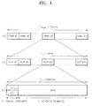
- FIGS. 1(a) through 1(c) illustrate a SCH in a hierarchical structure.
- FIG. 1(a) shows a single superframe composed of 72 frames. The duration of a single super frame is 720 ms.
- FIG. 1(b) shows a single frame composed of 15 slots. The duration of a single frame is 10 ms.
- FIG. 1(c) shows a single slot composed of a p-CCPCH composed of 9 symbols and a PSC C p and a SSC C s i which are each composed of one symbol. The duration of a single slot is 0.667 ms, and one symbol is composed of 256 chips.
- Each of the PSC and the SSC is a code sequence composed of 256 chips.
- the PSC is orthogonal to the SSC.
- a cell search is performed using a SCH. The boundary of a slot is found through the slot synchronization, and a code group is identified based on the correlation between the SSC and a received signal. Once the code group is identified, a scrambling code allocated to each cell is detected.
- the SCH signal of the received slot is correlated with the 16 SSCs, and the SSC which gives the maximum correlation value is detected.
- the performance is degraded due to various factors.
- the primary factors of the degradation of performance are noise, a change in a channel due to the movement of a MS, a frequency error due to a mismatch between the oscillators of a transmitter and a receiver and so on.
- the frequency error is an unavoidable phenomenon due to the physical characteristics of a device in a communication system and considerably degrades the performance of the system.
- a frequency error exerts a bad influence on a correlation property.
- a cell search probability decreases, and a cell search time increases.
- a combining method includes a coherent combining method and a noncoherent combining method.
- the coherent combining method is robust to noise but degrades the performance more severely when a channel state is changed severely or a frequency error occurs.
- the noncoherent combining method is robust to a channel state change and a frequency error but severely degrades the performance when a signal to noise ratio (SNR) is decreased due to much noise.
- SNR signal to noise ratio
- AWGN additive white Gaussian noise
- a cell searching apparatus which searches for a cell based on a received asynchronous wideband DS/CDMA signal in a receiver, the received signal including a data channel and a synchronous channel composed of a primary synchronization code commonly used in every cell and a secondary synchronization code indicating a code group unique to each cell.
- the cell searching apparatus includes a code group identifying unit for estimating and compensating for a frequency error between the synchronous channel and an internally generated primary synchronization code, estimating and compensating for channel characteristics which the synchronous channel has experienced, and correlating the compensated synchronous channel with available secondary synchronization codes, thereby identifying the code group; and a scrambling code identifying unit for correlating a plurality of scrambling codes belonging to the code group with the data channel, thereby obtaining a scrambling code unique to each cell.
- the apparatus of the invention enables searching for a cell through frequency error and channel estimation. Compensation for a received signal uses estimated values, and coherent combination of the results of the correlation between the compensated signal and secondary synchronization codes (SSCs) is employed.
- SSCs secondary synchronization codes
- This apparatus can be used in an asynchronous wideband direct-sequence code division multiple access (DS/CDMA) receiver.
- a method of acquiring a scrambling code included in a code group from an asynchronous wideband DS/CDMA signal received in an asynchronous wideband DS/CDMA receiver the received signal including a data channel and a synchronous channel composed of a primary synchronization code commonly used in every cell and a secondary synchronization code indicating a unique code group of each cell, the scrambling code being a spreading code unique to each cell.
- the method includes the steps of (a) estimating and compensating for a frequency error between the synchronous channel and a primary synchronization code generated by a primary synchronization code generator; (b) estimating and compensating for characteristics of a channel which the synchronous channel has experienced; (c) correlating the compensated synchronous channel with available secondary synchronization codes, thereby identifying a secondary synchronization code included in the synchronous channel; and (d) correlating a plurality of scrambling codes belonging to a code group represented by the secondary synchronization code with the data channel to obtain a scrambling code unique to each cell.
- the method of the invention enables a code unique to each cell to acquired , again using frequency error and channel estimation.
- a wideband direct-sequence code division multiple access (DS/CDMA) receiver includes an antenna 200, a radio frequency (RF) receiver 210, a down converter 220, a low-pass filter (LPF) 230, an analog to digital converter (ADC) 240, a slot synchronizer 250, a code group identifying unit 260, a scrambling code identifying unit 270 and a demodulator 280.
- the slot synchronizer 250 includes a correlation unit 251, a primary synchronization code (PSC) generator 252, a PSC sync signal detector 253, a verifier 254 and a PSC sync signal adjustor 255.
- PSC primary synchronization code
- the code group identifying unit 260 includes a frequency error compensator 261, a channel compensator 262 and a code group identifier 263.
- the scrambling code identifying unit 270 includes a code sync signal adjustor 271, a scrambling code generator 272, a correlation unit 273 and a scrambling code identifier 274.
- the RF receiver 210 receives a RF signal via the antenna 200 and converts it into an intermediate frequency (IF) signal.
- the down converter 220, the LPF 230 and the ADC 240 convert the IF signal down to a baseband discrete signal.
- the slot synchronizer 250 detects the boundary of a slot from a Synchronous CHannel (SCH) output from the ADC 240. In other words, a point at which a peak is detected from the output of a matched filter for a PSC is a synchronous point of a slot.
- the correlation unit 251 correlates a PSC output from the PSC generator 252 with the output SCH of the ADC 240.
- the PSC sync signal detector 253 detects the sync signal of the slot from the output of the correlation unit 251.
- the PSC sync signal adjustor 255 adjusts the sync signal of the slot output from the PSC sync signal detector 253 to match it with the sync signal of the received signal and outputs the result of the adjustment to the PSC generator 252.
- the verifier 254 verifies whether the sync signal of the slot is detected by the PSC sync signal detector 253 and outputs the result of the verification to the correlation unit 251.
- the code group identifying unit 260 compensates the output SCH of the ADC 240 for a frequency error and for channel degradation to identify a code group.
- the code group is determined based on a secondary synchronization code (SSC).
- SSC secondary synchronization code
- a single frame is composed of 15 slots.
- One of 16 SSCs is transmitted simultaneously with a PSC for each slot. In other words, 15 SSCs are transmitted during the transmission of one frame.
- a code group is determined based on the consecutive 15 SSCs transmitted during the transmission of one frame.
- the code group identifying unit 260 identifies the code group and acquires the frame syn signal by detecting transmitted SSCs based on slot synchronization information obtained by the slot synchronizer and the results of correlations between the 16 SSCs and the output SCH of the ADC 240.
- the frequency error compensator 261 estimates the frequency error between the PSC generated by the PSC generator 252 and the output SCH of the ADC 240 and compensates the SCH output from the ADC 240 for the estimated frequency error.
- the output SCH of the ADC 240 includes a frequency error ⁇ caused by mismatch in oscillation frequency between a transmitter and a receiver.
- the channel compensator 262 estimates the characteristics of a complex channel from the output signal of the frequency error compensator 261 and compensates the output signal of the frequency error compensator 261 for the estimated characteristics.
- the code group identifier 263 correlates the output signal of the channel compensator 262 with the 16 SSCs and coherently combines the results of the correlations for every frame, thereby detecting SSCs and acquiring a frame synchronization.
- the scrambling code identifying unit 270 correlates 8 scrambling codes contained in the code group determined by the code group identifying unit 260 with the output data of the ADC 240 and obtains a scrambling code allocated to each cell.
- the code sync signal adjustor 271 adjusts the sync signal of a scrambling code using a frame sync signal detected by the code group identifier 263.
- the scrambling code generator 272 generates 8 scrambling codes belonging to the code group identified by the code group identifier 263 based on a sync signal adjusted by the code sync signal adjustor 271.
- the correlation unit 273 correlates the output data of the ADC 240 with each of the 8 scrambling codes generated by the scrambling code generator 272.
- the scrambling code identifier 274 identifies a scrambling code based on the results from the correlation unit 273.
- the demodulator 280 performs typical RAKE processing and demodulation and outputs data.
- FIG. 3 is a detailed block diagram illustrating the code group identifying unit 260 of FIG. 2.
- the frequency error compensator 261 includes a switch 301, a frequency error estimator 302, a numerically controlled oscillator (NCO) 303 and a multiplier 304.
- the channel compensator 262 includes a channel estimator 311, a complex conjugator 312 and a multiplier 313.
- the code group identifier 263 includes a correlation unit 321, a coherent combiner 322 and a code group identification and frame synchronization unit 323.
- the frequency error compensator 261 estimates a frequency error with respect to the output SCH of the ADC 240 and compensates for the estimated frequency error.
- the frequency error estimator 302 outputs an estimate 0 for the frequency error ⁇ between the output SCH of the ADC 240, which is input through the switch 301, and the PSC generated by the PSC generator 252.
- the NCO 303 generates a complex sinusoidal wave corresponding to the estimate 0.
- the multiplier 304 multiplies the complex sinusoidal wave output from the NCO 303 by the output SCH of the ADC 240 to compensate for the frequency error.
- the estimation of a frequency error will be described later in more detail with reference to FIG. 5.
- the channel compensator 262 estimates a channel characteristics included in the output SCH of the ADC 240 and compensates the output SCH of the ADC 240 for the estimated characteristics.
- the channel estimator 311 estimates channel characteristics using a typical method. Parameters necessary for channel estimation are updated for each slot using the correlation values between a signal whose frequency error has been compensated for by the multiplier 304 and a PSC.
- the complex conjugator 312 obtains a complex conjugate with respect to the estimated channel characteristics.
- the multiplier 313 multiplies the output signal of the multiplier 304 by the output of the complex conjugator 312 to compensate for the channel characteristics. Therefore, the frequency error and the influence of the channel characteristics can be removed from the output SCH of the ADC 240.
- the code group identifier 263 identifies a code group included in the output SCH of the ADC 240 and acquires a frame sync signal.
- the correlation unit 321 correlates the output signal of the multiplier 313 with the 16 SSCs.
- the correlation unit 321 performs 16-point fast Hadamard transform.
- the coherent combiner 322 coherently combines the outputs of the correlation unit 321 for every frame. It is preferable to use a coherent combining method because the frequency error and the influence of the channel characteristics have been removed.
- the code group identification and frame synchronization unit 323 detects a SSC at which the output value of the coherent combiner 322 exceeds a predetermined threshold or at which the output value is maximum.
- FIG. 4 is a detailed block diagram illustrating the coherent combiner 322.
- the coherent combiner 322 includes a plurality of adders 401 through 403 and a squarer 410.
- the adders 401 through 403 accumulatively add the outputs.
- the squarer 410 squares the sum of the outputs from the correlation unit 321 and outputs a coherently combined value Z as follows.
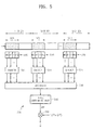
- FIG. 5 is a detailed block diagram for explaining the frequency error estimator 302 in detail.
- the frequency error estimator 302 includes a plurality of partial correlation units 500, 510 and 520, a plurality of dividers 501, 511 and 521, an averager 530, a phase arithmetic unit 540 and a multiplier 550.
- each of the partial correlation units 500, 510 and 520 divides the SCH of a 256-chip length in each slot into M blocks with respect to the output SCH of the ADC 240 and partially correlates the complex conjugate of the PSC generated by the PSC generator 252 with the M blocks of the SCH.
- the PSC is divided into M blocks having a chip length which is integral times of 16, and partial period correlation is performed on each block.
- M is one among 2, 4, 8 and 16.
- Each of the partial correlation units 500, 510 and 520 is preferably realized as a matched filter or an active correlator.
- the outputs of the partial correlation units 500, 510 and 520 are phase values.
- frequency error estimation is accomplished based on the correlation property in which a PSC is orthogonal to a SSC at every 16 chips as shown in Equation (2).
- n indicates the index of a SSC and is one of 1, 2, ... 16
- I is zero or a positive number larger than
- J is 1 or a positive number larger than 1
- ( I + J ) ⁇ 16 the orthogonal property between a PSC and a SSC is maintained even though partial period correlation is performed on only the PSC and SSC having a chip length which is integral times of 16, instead of performing entire period correlation on the 256-chip PSC and SSC.
- Equation (3) a complex signal of each chip received during the SCH period of a single slot.
- r(n) a complex signal of each chip received during the SCH period of a single slot.
- the complex signal r(n) can be expressed by Equation (3).
- x (n) is a transmitted complex SCH signal
- h (n) is a complex channel through which the signal has been transmitted
- N (n) is complex Gaussian noise.
- x (n) can be expressed by Equation (4). If there is a frequency error f e , r (n) changes into Equation (5).
- r(n) h(n)x(n)exp[j(2 ⁇ f e T c + ⁇ ] + N(n)
- T c is a chip duration
- ⁇ is a phase having a uniform distribution at a period [0, 2 ⁇ ].
- a signal received for a SCH period is divided into M blocks of a 16N-chip length.
- the signal is divided by a 16N-chip length in order to use the property in that a at least16-chip PSC is orthogonal to a at least 16-chip SSC.
- the first assumption is reasonable in an actual condition.
- the second assumption means that a signal has the same phase in a single period, and the phase difference between blocks separated from each other by 128 chips is the same as a phase variation due to a frequency error.
- a SCH signal received during a single period can be considered as a signal in which noise is added to the result of multiplying a transmitted signal by a complex constant so that the correlation property between a PSC and a SSC can be used.
- k is a positive number
- N m is a component generated due to noise as the result of performing correlation on the PSC and the received signal.
- the correlation result Y m is obtained with respect to the M blocks.
- a phase variation in a duration of 128 chips corresponding to M/2 blocks can be obtained from M correlation results Y m .
- the phase variation is obtained through the operations of the dividers 501, 511 and 521, the averager 530 and the phase arithmetic unit 540.
- each of the dividers 501, 511 and 521 pairs two values separated from each other by a length of 128 chips, that is, Y M/2+m and Y m , among the outputs of each of the partial correlation units 500, 510 and 520 and performs divisions such as Y M/2+m / Y m .
- the averager 530 averages the outputs of the dividers 501, 511 and 521.
- the phase arithmetic unit 540 obtains the phase of the output of the averager 530.
- a phase variation ⁇ may be obtained by individually obtaining the phases of respective outputs of the dividers 501, 511 and 521 and averaging the phases.
- the results of the above operations can be expressed by Equation (8).
- the multiplier 550 multiplies the phase variation ⁇ by 1/[2 ⁇ ( ⁇ T )] and outputs a frequency error estimate.
- ⁇ T is 128 Tc.
- the frequency error estimate is expressed by Equation (9).
- the present invention estimates a frequency error and compensates for the error, thereby improving the performance of searching for a cell and eventually reducing the cell search time.
- a cell search can be accomplished only by adding a simple operation so that the burden of additional hardware can be reduced.
- the method of estimating and compensating for a frequency error can be applied to automatic frequency control or NCO control in a software, wireless system.
Landscapes
- Engineering & Computer Science (AREA)
- Computer Networks & Wireless Communication (AREA)
- Signal Processing (AREA)
- Mobile Radio Communication Systems (AREA)
- Synchronisation In Digital Transmission Systems (AREA)
Abstract
Description


Claims (10)
- A cell searching apparatus which searches for a cell based on a received asynchronous wideband direct-sequence code division multiple access (DS/CDMA) signal in a receiver, the received signal including a data channel and a synchronous channel composed of a primary synchronization code commonly used in every cell and a secondary synchronization code indicating a code group unique to each cell, the cell searching apparatus comprising:a code group identifying unit for estimating and compensating for a frequency error between the synchronous channel and an internally generated primary synchronization code, estimating and compensating for channel characteristics which the synchronous channel has experienced, and correlating the compensated synchronous channel with available secondary synchronization codes, thereby identifying the code group; anda scrambling code identifying unit for correlating a plurality of scrambling codes belonging to the code group with the data channel, thereby obtaining a scrambling code unique to each cell.
- The cell searching apparatus of claim 1, wherein the code group identifying unit comprises:a primary synchronization code generator,a frequency error compensator for estimating a frequency error between the synchronous channel and a primary synchronization code generated by the primary synchronization code generator and compensating the synchronous channel for the estimated frequency error;a channel compensator for estimating channel characteristics from the frequency error compensated synchronous channel and compensating the frequency error compensated synchronous channel for the estimated channel characteristics; anda code group identifier for combining the results of correlating the channel characteristics compensated synchronous channel with the available plurality of primary synchronization codes, thereby identifying the code group.
- The cell searching apparatus of claim 2, wherein the frequency error compensator comprises:a switch having one end operating such that the synchronous channel can be received;a frequency error estimator connected to the other end of the switch, the frequency error estimator obtaining the phase difference between the synchronous channel and the primary synchronization code generated by the primary synchronization code generator and converting the phase difference into a frequency error;a numerically controlled oscillator for generating a complex sinusoidal wave corresponding to the frequency error; anda multiplier connected to the other end of the switch, the multiplier multiplying the synchronous channel input through the switch by the complex sinusoidal wave.
- The cell searching apparatus of claim 3, wherein the frequency error estimator comprises:a plurality of partial correlation units each for correlating the synchronous channel divided into a predetermined number of blocks in each slot with the primary synchronization code generated by the primary synchronization code generator;a divider for dividing one output by another output among the outputs of the partial correlation units, the two outputs being separated from each other by a predetermined chip duration;a phase arithmetic unit for obtaining a phase from the outputs of the divider; anda multiplier for converting the phase into a frequency by dividing the output of the phase arithmetic unit by the predetermined period of time.
- The cell searching apparatus of claim 4, wherein the frequency error estimator further comprises an averager for summing up the output of the divider a predetermined number of times and averaging the sum of the outputs using the predetermined number of times.
- The cell searching apparatus of claim 2, wherein the code group identifier comprises:a plurality of correlation units for correlating the output of the channel compensator with the plurality of secondary synchronization codes;a coherent combiner for summing up the outputs of the correlation units and squaring the sum of the outputs; anda selection means for selecting a secondary synchronization code at which the output of the coherent combiner exceeds a predetermined value.
- A method of acquiring a scrambling code included in a code group from an asynchronous wideband direct-sequence code division multiple access (DS/CDMA) signal received in an asynchronous wideband DS/CDMA receiver, the received signal including a data channel and a synchronous channel composed of a primary synchronization code commonly used in every cell and a secondary synchronization code indicating a unique code group of each cell, the scrambling code being a spreading code unique to each cell, the method comprising the steps of:(a) estimating and compensating for a frequency error between the synchronous channel and a primary synchronization code generated by a primary synchronization code generator;(b) estimating and compensating for characteristics of a channel which the synchronous channel has experienced;(c) correlating the compensated synchronous channel with available secondary synchronization codes, thereby identifying a secondary synchronization code included in the synchronous channel; and(d) correlating a plurality of scrambling codes belonging to a code group represented by the secondary synchronization code with the data channel to obtain a scrambling code unique to each cell.
- The method of claim 7, wherein the step (a) comprises the steps of:(a1) dividing the synchronous channel into a predetermined number of blocks in each slot and correlating the divided synchronous channel with the primary synchronization code generated by the primary synchronization code generator;(a2) dividing one output by the other output among the results of the correlation, the two results of the correlation being separated from each other by a predetermined chip duration;(a3) obtaining a phase from the result of the division;(a4) dividing the phase by the predetermined period of time to convert the phase into a frequency; and(a5) compensating the synchronous channel for the frequency.
- The method of claim 8, wherein in the step (a1), each of the blocks of the synchronous channel has a chip length which is integral times of 16.
- The method of claim 8, wherein in the step (a2), the predetermined period of time corresponds to 1/2 of a chip length of the synchronous channel.
Applications Claiming Priority (2)
| Application Number | Priority Date | Filing Date | Title |
|---|---|---|---|
| KR2000001190 | 2000-01-11 | ||
| KR1020000001190A KR100319927B1 (en) | 2000-01-11 | 2000-01-11 | Apparatus for cell search and method for acquiring the code perculiar to each cell in asynchronous wideband CDMA receiver |
Publications (3)
| Publication Number | Publication Date |
|---|---|
| EP1117188A2 true EP1117188A2 (en) | 2001-07-18 |
| EP1117188A3 EP1117188A3 (en) | 2003-07-09 |
| EP1117188B1 EP1117188B1 (en) | 2005-06-08 |
Family
ID=19637825
Family Applications (1)
| Application Number | Title | Priority Date | Filing Date |
|---|---|---|---|
| EP20010300164 Expired - Lifetime EP1117188B1 (en) | 2000-01-11 | 2001-01-10 | Method and apparatus for cell searching in an asynchronous wideband CDMA receiver |
Country Status (6)
| Country | Link |
|---|---|
| US (1) | US6888880B2 (en) |
| EP (1) | EP1117188B1 (en) |
| JP (1) | JP2001231071A (en) |
| KR (1) | KR100319927B1 (en) |
| CN (1) | CN1179509C (en) |
| DE (1) | DE60111278T2 (en) |
Cited By (8)
| Publication number | Priority date | Publication date | Assignee | Title |
|---|---|---|---|---|
| EP1241817A4 (en) * | 2000-10-06 | 2003-01-22 | Yozan Inc | Receiver |
| GB2382478A (en) * | 2001-11-26 | 2003-05-28 | Ubinetics Ltd | Determining the approximate frequency error of an oscillator |
| EP1385273A4 (en) * | 2001-08-07 | 2004-04-14 | Matsushita Electric Industrial Co Ltd | DEVICE AND METHOD FOR SEARCHING CELLS |
| US6888880B2 (en) * | 2000-01-11 | 2005-05-03 | Samsung Electronics Co., Ltd. | Apparatus for searching for a cell and method of acquiring code unique to each cell in an asynchronous wideband DS/CDMA receiver |
| EP1456971A4 (en) * | 2001-12-20 | 2006-11-22 | Interdigital Tech Corp | Cell search using peak quality factors |
| CN1540896B (en) * | 2003-04-24 | 2010-04-07 | 上海明波通信技术有限公司 | Method for searching cell and implementation equipment thereof |
| EP1638448A4 (en) * | 2003-07-02 | 2011-09-28 | Thomson Licensing | METHOD AND DEVICE FOR THE FREQUENCY ROBUST DETECTION OF A BROADBAND CODE DIVISION MULTIPLE ACCESS SECONDARY SYNCHRONIZATION CHANNEL |
| US11804870B2 (en) | 2004-01-29 | 2023-10-31 | Neo Wireless Llc | Channel probing signal for a broadband communication system |
Families Citing this family (44)
| Publication number | Priority date | Publication date | Assignee | Title |
|---|---|---|---|---|
| DE60044928D1 (en) * | 1999-04-29 | 2010-10-21 | Samsung Electronics Co Ltd | DEVICE AND METHOD FOR SYNCRONIZING CHANNELS IN A BROADBAND W-CDMA COMMUNICATION SYSTEM |
| JP2001244849A (en) * | 2000-02-29 | 2001-09-07 | Matsushita Electric Ind Co Ltd | Communication terminal device and cell search method |
| US6826244B2 (en) * | 2001-02-27 | 2004-11-30 | Interdigital Technology Corporation | Initial cell search algorithm for 3G FDD wireless communication systems |
| CN1138428C (en) * | 2001-06-11 | 2004-02-11 | 华为技术有限公司 | Method for selecting synchronous code in synchronizing system of mobile communication |
| US7817596B2 (en) * | 2001-09-06 | 2010-10-19 | Qualcomm Incorporated | Verification methods and apparatus for improving acquisition searches of asynchronous cells |
| KR100591700B1 (en) * | 2001-10-06 | 2006-07-03 | 엘지노텔 주식회사 | Signal path search method in array antenna system and apparatus for same |
| US7356098B2 (en) * | 2001-11-14 | 2008-04-08 | Ipwireless, Inc. | Method, communication system and communication unit for synchronisation for multi-rate communication |
| US7693123B2 (en) * | 2001-11-29 | 2010-04-06 | Interdigital Technology Corporation | System and method using primary and secondary synchronization codes during cell search |
| US20050117632A1 (en) * | 2002-01-07 | 2005-06-02 | Yanmeng Sun | Mobile terminal for cell searching via an iterative correlation system |
| US7126981B2 (en) * | 2002-04-25 | 2006-10-24 | Accton Technology Corporation | Method and apparatus for cell search for W-CDMA with effect of clock offset |
| CN100425015C (en) * | 2002-05-16 | 2008-10-08 | 智邦科技股份有限公司 | coherent detection and decoding method and device |
| US7369577B2 (en) * | 2002-05-16 | 2008-05-06 | Stmicroelectronics, Inc. | Code group acquisition procedure for a UMTS-FDD receiver |
| TWI224740B (en) * | 2002-07-31 | 2004-12-01 | Interdigital Tech Corp | Start-up automatic frequency control (AFC) method and apparatus |
| US7643596B2 (en) * | 2002-09-09 | 2010-01-05 | Infineon Technologies Ag | Method and device for synchronizing a mobile radio receiver with a base station involving parallel verification |
| KR100950904B1 (en) * | 2003-02-05 | 2010-04-06 | 인터디지탈 테크날러지 코포레이션 | Initial Cell Search Method in Wireless Communication System |
| US7126528B2 (en) * | 2003-02-28 | 2006-10-24 | Southwest Research Institute | Method for delivering secondary (non-location) data to a GPS receiver |
| WO2004112277A1 (en) * | 2003-06-13 | 2004-12-23 | Siemens Aktiengesellschaft | Power control for a mobile radio communication system |
| US7254163B2 (en) * | 2003-12-31 | 2007-08-07 | Benq Corporation | Method for WCDMA frame synchronization and related device |
| US7224718B2 (en) * | 2003-06-17 | 2007-05-29 | Benq Corporation | Slot synchronization for a CDMA system |
| CN1820437A (en) * | 2003-08-04 | 2006-08-16 | 汤姆森许可贸易公司 | Frequency synchronization during cell searching in universal mobile telephone system receiver |
| US7746760B2 (en) * | 2004-01-08 | 2010-06-29 | Qualcomm Incorporated | Frequency error estimation and frame synchronization in an OFDM system |
| CN100382464C (en) * | 2004-06-10 | 2008-04-16 | 大唐移动通信设备有限公司 | TD-SCDMA system cell code word planning method and method for searching composite code word combination thereof |
| CN100375559C (en) * | 2004-07-13 | 2008-03-12 | 中兴通讯股份有限公司 | Code resource allocation method in multi-carrier cell |
| US7561615B2 (en) * | 2005-03-18 | 2009-07-14 | Interdigital Technology Corporation | Method and apparatus for compensating for phase noise of symbols spread with a long spreading code |
| US7391320B1 (en) | 2005-04-01 | 2008-06-24 | Horizon Hobby, Inc. | Method and system for controlling radio controlled devices |
| JP4546342B2 (en) | 2005-07-07 | 2010-09-15 | パナソニック株式会社 | Transmitting apparatus and transmitting method |
| KR101184559B1 (en) * | 2005-08-17 | 2012-09-20 | 지티이 코포레이션 | Method of configuring and searching high speed shared control channel of multi carrier cell |
| US7965759B2 (en) * | 2005-10-28 | 2011-06-21 | Qualcomm Incorporated | Synchronization codes for wireless communication |
| CN102571138B (en) | 2005-12-20 | 2015-02-11 | Lg电子株式会社 | Method of generating code sequence and method of transmitting signal using the same |
| US8830983B2 (en) | 2005-12-20 | 2014-09-09 | Lg Electronics Inc. | Method of generating code sequence and method of transmitting signal using the same |
| US7983143B2 (en) * | 2006-02-08 | 2011-07-19 | Motorola Mobility, Inc. | Method and apparatus for initial acquisition and cell search for an OFDMA system |
| US7911935B2 (en) | 2006-02-08 | 2011-03-22 | Motorola Mobility, Inc. | Method and apparatus for interleaving sequence elements of an OFDMA synchronization channel |
| WO2007097597A2 (en) * | 2006-02-24 | 2007-08-30 | Lg Electronics Inc. | Methods of searching code sequence in mobile communication system |
| US20080063046A1 (en) * | 2006-09-12 | 2008-03-13 | Johannes Hendrik Conroy | Method and System for Estimating Signal Error in a Communication System |
| CA2665218C (en) * | 2006-10-03 | 2013-07-16 | Qualcomm Incorporated | Method and apparatus for processing primary and secondary synchronization signals for wireless communication |
| KR100763580B1 (en) | 2006-10-31 | 2007-10-04 | 한국전자통신연구원 | Apparatus and method for identifying signal analysis using partial correlation |
| KR100921769B1 (en) * | 2007-07-12 | 2009-10-15 | 한국전자통신연구원 | Downlink frame generation method and cell search method |
| KR20090009693A (en) | 2007-07-20 | 2009-01-23 | 한국전자통신연구원 | Downlink frame generation method and cell search method |
| KR20090022082A (en) * | 2007-08-29 | 2009-03-04 | 삼성전자주식회사 | Mobile communication network and cell discovery method and mobile communication network system for same |
| US20090190704A1 (en) * | 2008-01-24 | 2009-07-30 | Horizon Semiconductors Ltd. | Synchronization of frame signals having two synchronization words |
| FR2942576B1 (en) * | 2009-02-23 | 2011-02-18 | Commissariat Energie Atomique | METHOD OF ESTIMATING A CARRIER FREQUENCY OFFSET IN A TELECOMMUNICATION SIGNAL RECEIVER, IN PARTICULAR A MOBILE DEVICE |
| US20100304744A1 (en) * | 2009-05-29 | 2010-12-02 | Qualcomm Incorporated | Method and apparatus for performing searches with multiple receive diversity (rxd) search modes |
| US8903092B2 (en) * | 2010-06-04 | 2014-12-02 | Maxim Integrated Products, Inc. | High speed digital to analog converter with reduced spurious outputs |
| CN112821895B (en) * | 2021-04-16 | 2021-07-09 | 成都戎星科技有限公司 | Code identification method for realizing high error rate of signal |
Family Cites Families (4)
| Publication number | Priority date | Publication date | Assignee | Title |
|---|---|---|---|---|
| JP3323453B2 (en) * | 1999-02-09 | 2002-09-09 | 松下電器産業株式会社 | CDMA receiving apparatus and CDMA receiving method |
| EP1035665A1 (en) * | 1999-03-10 | 2000-09-13 | Robert Bosch Gmbh | Method for the initial synchronization of a digital mobile radio system |
| DE60044928D1 (en) * | 1999-04-29 | 2010-10-21 | Samsung Electronics Co Ltd | DEVICE AND METHOD FOR SYNCRONIZING CHANNELS IN A BROADBAND W-CDMA COMMUNICATION SYSTEM |
| KR100319927B1 (en) * | 2000-01-11 | 2002-01-09 | 윤종용 | Apparatus for cell search and method for acquiring the code perculiar to each cell in asynchronous wideband CDMA receiver |
-
2000
- 2000-01-11 KR KR1020000001190A patent/KR100319927B1/en not_active Expired - Fee Related
-
2001
- 2001-01-10 EP EP20010300164 patent/EP1117188B1/en not_active Expired - Lifetime
- 2001-01-10 DE DE2001611278 patent/DE60111278T2/en not_active Expired - Fee Related
- 2001-01-11 US US09/758,040 patent/US6888880B2/en not_active Expired - Fee Related
- 2001-01-11 JP JP2001003213A patent/JP2001231071A/en not_active Withdrawn
- 2001-01-11 CN CNB011113154A patent/CN1179509C/en not_active Expired - Fee Related
Cited By (9)
| Publication number | Priority date | Publication date | Assignee | Title |
|---|---|---|---|---|
| US6888880B2 (en) * | 2000-01-11 | 2005-05-03 | Samsung Electronics Co., Ltd. | Apparatus for searching for a cell and method of acquiring code unique to each cell in an asynchronous wideband DS/CDMA receiver |
| EP1241817A4 (en) * | 2000-10-06 | 2003-01-22 | Yozan Inc | Receiver |
| EP1385273A4 (en) * | 2001-08-07 | 2004-04-14 | Matsushita Electric Industrial Co Ltd | DEVICE AND METHOD FOR SEARCHING CELLS |
| US7013135B2 (en) | 2001-08-07 | 2006-03-14 | Matsushita Electric Industrial Co., Ltd. | Cell searcher and cell searching method |
| GB2382478A (en) * | 2001-11-26 | 2003-05-28 | Ubinetics Ltd | Determining the approximate frequency error of an oscillator |
| EP1456971A4 (en) * | 2001-12-20 | 2006-11-22 | Interdigital Tech Corp | Cell search using peak quality factors |
| CN1540896B (en) * | 2003-04-24 | 2010-04-07 | 上海明波通信技术有限公司 | Method for searching cell and implementation equipment thereof |
| EP1638448A4 (en) * | 2003-07-02 | 2011-09-28 | Thomson Licensing | METHOD AND DEVICE FOR THE FREQUENCY ROBUST DETECTION OF A BROADBAND CODE DIVISION MULTIPLE ACCESS SECONDARY SYNCHRONIZATION CHANNEL |
| US11804870B2 (en) | 2004-01-29 | 2023-10-31 | Neo Wireless Llc | Channel probing signal for a broadband communication system |
Also Published As
| Publication number | Publication date |
|---|---|
| JP2001231071A (en) | 2001-08-24 |
| KR20010068996A (en) | 2001-07-23 |
| EP1117188A3 (en) | 2003-07-09 |
| US6888880B2 (en) | 2005-05-03 |
| EP1117188B1 (en) | 2005-06-08 |
| KR100319927B1 (en) | 2002-01-09 |
| CN1179509C (en) | 2004-12-08 |
| DE60111278D1 (en) | 2005-07-14 |
| CN1307415A (en) | 2001-08-08 |
| US20010021199A1 (en) | 2001-09-13 |
| DE60111278T2 (en) | 2006-03-16 |
Similar Documents
| Publication | Publication Date | Title |
|---|---|---|
| EP1117188B1 (en) | Method and apparatus for cell searching in an asynchronous wideband CDMA receiver | |
| US6154487A (en) | Spread-spectrum signal receiving method and spread-spectrum signal receiving apparatus | |
| US8345714B2 (en) | Cell search method and apparatus for asynchronous mobile communication system | |
| JP4701572B2 (en) | Timing acquisition / offset correction method and apparatus | |
| EP1289163B1 (en) | Frequency offset correction circuit for WCDMA | |
| JP2013258723A (en) | Signal acquisition in wireless communication system | |
| KR20010013556A (en) | Synchronizer and Method therefor and Communications System Incorporating Same | |
| JP3924778B2 (en) | Frequency offset estimation method in direct spread spectrum communication receiver | |
| JP4710210B2 (en) | Offset correction method and apparatus | |
| EP1564903B1 (en) | Apparatus and method for estimating initial frequency offset in an asynchronous mobile communication system | |
| JP3418981B2 (en) | Spread spectrum communication synchronization acquisition circuit | |
| GB2368751A (en) | Iterative adjustment of the reference oscillator frequency offset in a receiver | |
| EP1914950B1 (en) | Method and arrangement for automatic frequency correction | |
| WO2002089347A1 (en) | Device for synchronizing a receiver and a transmitter in a communication system | |
| TWI462539B (en) | Frequency correction method | |
| KR100353840B1 (en) | Apparatus and method for serearching cell in wireless communication system | |
| KR100940926B1 (en) | Method and system for estimating signal error in communication system | |
| JP2002198861A (en) | Spread spectrum receiver and spread spectrum receiving method | |
| JP2000269933A (en) | Spread spectrum communication equipment |
Legal Events
| Date | Code | Title | Description |
|---|---|---|---|
| PUAI | Public reference made under article 153(3) epc to a published international application that has entered the european phase |
Free format text: ORIGINAL CODE: 0009012 |
|
| AK | Designated contracting states |
Kind code of ref document: A2 Designated state(s): AT BE CH CY DE DK ES FI FR GB GR IE IT LI LU MC NL PT SE TR |
|
| AX | Request for extension of the european patent |
Free format text: AL;LT;LV;MK;RO;SI |
|
| PUAL | Search report despatched |
Free format text: ORIGINAL CODE: 0009013 |
|
| AK | Designated contracting states |
Designated state(s): AT BE CH CY DE DK ES FI FR GB GR IE IT LI LU MC NL PT SE TR |
|
| AX | Request for extension of the european patent |
Extension state: AL LT LV MK RO SI |
|
| 17P | Request for examination filed |
Effective date: 20030820 |
|
| 17Q | First examination report despatched |
Effective date: 20031202 |
|
| AKX | Designation fees paid |
Designated state(s): DE FR GB |
|
| GRAP | Despatch of communication of intention to grant a patent |
Free format text: ORIGINAL CODE: EPIDOSNIGR1 |
|
| GRAS | Grant fee paid |
Free format text: ORIGINAL CODE: EPIDOSNIGR3 |
|
| GRAA | (expected) grant |
Free format text: ORIGINAL CODE: 0009210 |
|
| AK | Designated contracting states |
Kind code of ref document: B1 Designated state(s): DE FR GB |
|
| REG | Reference to a national code |
Ref country code: GB Ref legal event code: FG4D |
|
| REF | Corresponds to: |
Ref document number: 60111278 Country of ref document: DE Date of ref document: 20050714 Kind code of ref document: P |
|
| ET | Fr: translation filed | ||
| PLBE | No opposition filed within time limit |
Free format text: ORIGINAL CODE: 0009261 |
|
| STAA | Information on the status of an ep patent application or granted ep patent |
Free format text: STATUS: NO OPPOSITION FILED WITHIN TIME LIMIT |
|
| 26N | No opposition filed |
Effective date: 20060309 |
|
| PGFP | Annual fee paid to national office [announced via postgrant information from national office to epo] |
Ref country code: DE Payment date: 20090123 Year of fee payment: 9 |
|
| PGFP | Annual fee paid to national office [announced via postgrant information from national office to epo] |
Ref country code: GB Payment date: 20090114 Year of fee payment: 9 |
|
| PGFP | Annual fee paid to national office [announced via postgrant information from national office to epo] |
Ref country code: FR Payment date: 20090113 Year of fee payment: 9 |
|
| GBPC | Gb: european patent ceased through non-payment of renewal fee |
Effective date: 20100110 |
|
| REG | Reference to a national code |
Ref country code: FR Ref legal event code: ST Effective date: 20100930 |
|
| PG25 | Lapsed in a contracting state [announced via postgrant information from national office to epo] |
Ref country code: FR Free format text: LAPSE BECAUSE OF NON-PAYMENT OF DUE FEES Effective date: 20100201 |
|
| PG25 | Lapsed in a contracting state [announced via postgrant information from national office to epo] |
Ref country code: DE Free format text: LAPSE BECAUSE OF NON-PAYMENT OF DUE FEES Effective date: 20100803 |
|
| PG25 | Lapsed in a contracting state [announced via postgrant information from national office to epo] |
Ref country code: GB Free format text: LAPSE BECAUSE OF NON-PAYMENT OF DUE FEES Effective date: 20100110 |