EP1116636A1 - Railway vehicle and railway vehicle use bogie car - Google Patents
Railway vehicle and railway vehicle use bogie car Download PDFInfo
- Publication number
- EP1116636A1 EP1116636A1 EP00306800A EP00306800A EP1116636A1 EP 1116636 A1 EP1116636 A1 EP 1116636A1 EP 00306800 A EP00306800 A EP 00306800A EP 00306800 A EP00306800 A EP 00306800A EP 1116636 A1 EP1116636 A1 EP 1116636A1
- Authority
- EP
- European Patent Office
- Prior art keywords
- connection member
- particle shape
- vibrations
- railway vehicle
- car body
- Prior art date
- Legal status (The legal status is an assumption and is not a legal conclusion. Google has not performed a legal analysis and makes no representation as to the accuracy of the status listed.)
- Granted
Links
Images


Classifications
-
- B—PERFORMING OPERATIONS; TRANSPORTING
- B61—RAILWAYS
- B61F—RAIL VEHICLE SUSPENSIONS, e.g. UNDERFRAMES, BOGIES OR ARRANGEMENTS OF WHEEL AXLES; RAIL VEHICLES FOR USE ON TRACKS OF DIFFERENT WIDTH; PREVENTING DERAILING OF RAIL VEHICLES; WHEEL GUARDS, OBSTRUCTION REMOVERS OR THE LIKE FOR RAIL VEHICLES
- B61F3/00—Types of bogies
-
- F—MECHANICAL ENGINEERING; LIGHTING; HEATING; WEAPONS; BLASTING
- F16—ENGINEERING ELEMENTS AND UNITS; GENERAL MEASURES FOR PRODUCING AND MAINTAINING EFFECTIVE FUNCTIONING OF MACHINES OR INSTALLATIONS; THERMAL INSULATION IN GENERAL
- F16F—SPRINGS; SHOCK-ABSORBERS; MEANS FOR DAMPING VIBRATION
- F16F7/00—Vibration-dampers; Shock-absorbers
- F16F7/01—Vibration-dampers; Shock-absorbers using friction between loose particles, e.g. sand
- F16F7/015—Vibration-dampers; Shock-absorbers using friction between loose particles, e.g. sand the particles being spherical, cylindrical or the like
-
- B—PERFORMING OPERATIONS; TRANSPORTING
- B60—VEHICLES IN GENERAL
- B60G—VEHICLE SUSPENSION ARRANGEMENTS
- B60G7/00—Pivoted suspension arms; Accessories thereof
- B60G7/02—Attaching arms to sprung part of vehicle
-
- B—PERFORMING OPERATIONS; TRANSPORTING
- B61—RAILWAYS
- B61F—RAIL VEHICLE SUSPENSIONS, e.g. UNDERFRAMES, BOGIES OR ARRANGEMENTS OF WHEEL AXLES; RAIL VEHICLES FOR USE ON TRACKS OF DIFFERENT WIDTH; PREVENTING DERAILING OF RAIL VEHICLES; WHEEL GUARDS, OBSTRUCTION REMOVERS OR THE LIKE FOR RAIL VEHICLES
- B61F5/00—Constructional details of bogies; Connections between bogies and vehicle underframes; Arrangements or devices for adjusting or allowing self-adjustment of wheel axles or bogies when rounding curves
- B61F5/02—Arrangements permitting limited transverse relative movements between vehicle underframe or bolster and bogie; Connections between underframes and bogies
-
- B—PERFORMING OPERATIONS; TRANSPORTING
- B60—VEHICLES IN GENERAL
- B60G—VEHICLE SUSPENSION ARRANGEMENTS
- B60G2202/00—Indexing codes relating to the type of spring, damper or actuator
- B60G2202/20—Type of damper
- B60G2202/23—Friction Damper
-
- B—PERFORMING OPERATIONS; TRANSPORTING
- B60—VEHICLES IN GENERAL
- B60G—VEHICLE SUSPENSION ARRANGEMENTS
- B60G2202/00—Indexing codes relating to the type of spring, damper or actuator
- B60G2202/20—Type of damper
- B60G2202/25—Dynamic damper
-
- B—PERFORMING OPERATIONS; TRANSPORTING
- B60—VEHICLES IN GENERAL
- B60G—VEHICLE SUSPENSION ARRANGEMENTS
- B60G2206/00—Indexing codes related to the manufacturing of suspensions: constructional features, the materials used, procedures or tools
- B60G2206/01—Constructional features of suspension elements, e.g. arms, dampers, springs
- B60G2206/10—Constructional features of arms
- B60G2206/11—Constructional features of arms the arm being a radius or track or torque or steering rod or stabiliser end link
-
- B—PERFORMING OPERATIONS; TRANSPORTING
- B60—VEHICLES IN GENERAL
- B60G—VEHICLE SUSPENSION ARRANGEMENTS
- B60G2206/00—Indexing codes related to the manufacturing of suspensions: constructional features, the materials used, procedures or tools
- B60G2206/01—Constructional features of suspension elements, e.g. arms, dampers, springs
- B60G2206/60—Subframe construction
- B60G2206/601—Hanger bracket
-
- B—PERFORMING OPERATIONS; TRANSPORTING
- B60—VEHICLES IN GENERAL
- B60G—VEHICLE SUSPENSION ARRANGEMENTS
- B60G2300/00—Indexing codes relating to the type of vehicle
- B60G2300/10—Railway vehicles
Definitions
- the present invention relates to a railway vehicle and a railway vehicle use bogie car.
- a bogie frame and a car body of a railway vehicle are connected according to a traction link (hereinafter it is called as a "link"). Both ends of the link, namely in a before and back direction a rubber bush is arranged. The rubber bush is designed to endure fully against a compression load which occurs some times in the before and back direction (in a link direction). Further, the link is connected to a connection member, it is called as a center pin which is projected in a lower portion from a lower face of the car body.
- the vibrations of the before and back direction are transmitted to a car body side through two rubber bushes and a link etc.. For this reason, noises in the inner side car becomes high.
- a solid propagation vibrations having a rotation frequency component of 80-300 Hz band area which is generated by an unbalance of a drive system are transmitted to the bogie frame and these vibrations are made to vibrate the floor, accordingly there is a problem about the increase of the noises in the inner side car.
- the rotation vibration component of f1 is 80 Hz
- the rotation vibration component of 2f1 is 160 Hz
- the rotation vibration component of 3f1 is 240 Hz
- the rotation vibration component of 4f1 is 320 Hz. For this reason, it is required to reduce the vibrations about more than 100 Hz.
- an object of the present invention is to a railway vehicle and a railway vehicle use bogie car wherein noises in an inner side car can be reduced by a simple construction.
- the present invention provides a railway vehicle wherein a connection member which is lifted down to a lower face of a car body and a bogie frame are connected according to a traction link and in an interior portion of the connection member a large number of particle shape members are movably accommodated.
- the present invention provides a railway vehicle use bogie car wherein a connection member which is lifted down to a lower face of a car body and a bogie frame are connected according to a traction link and in an interior portion of the connection member a large number of particle shape members are movably accommodated.
- a bogie frame 11 of a bogie car is supported by two car axles 13 having a vehicle wheel 12 and supports a reduction gear unit which comprises an electric motor 14 for driving the wheel axles 13 and gears.
- the bogie car frame 11 supports a car body 20 through an air cushion member 15.
- connection member 40 (in generally, it is called as a "center pin") which is projected in a lower portion from a lower face of the car body and the bogie frame 11 are connected according to a traction link 30 (herein, it is called as a "link”).
- the link 30 transmits a before and back force and this link is arranged along to a horizontal direction of a running direction.
- End portions of a right and a left of the bogie frame 11 are connected to the car body 20 through yaw dampers 28 and 28. Both end portions of the yaw damper 28 are connected to the bogie car frame 11 and the car body 20 through a rubber bush similarly to the link 30.
- the yaw damper 28 can prevent the meandering move during the running time.
- Both end portions of the link 30 are connected to the bogie car 11 and the connection member 40 through a rubber bush 35 and a pin 36, etc..
- the connection member 40 is arranged inclined for directing for a connection portion between from the car body 20 to the link 30.
- a cross-section of a lower end portion of a coupling member 45 of the connection member 40 is a reversal U shape.
- the link 30 is arranged in the horizontal direction of the running direction of the car body 20 and penetrates through the above stated U shape portion of the coupling member 45.
- the tip end of a second portion 42 of the connection member 40 has the coupling member 45.
- the U-shape cross-sectional coupling 31 is arranged to the bogie frame 11 and a coupling member 45 of the connection member 40.
- This construction has public known technique.
- connection member 40 has a horizontal cross-section having a quadrilateral shape and using a plate for constituting four faces it is constituted according to a welding manner.
- An upper face flange 43 is fixed to a lower face of the car body 20 through bolt means.
- An interior portion of the plate for constituting the four faces, reinforcement plates 44 are welded with plural stages in the upper and lower direction. In the reinforce plate 44, a hole 47 is opened in a central portion.
- the vibration control use many or a large number of particle shape members 50 are accommodated.
- the particle shape members 50 are inserted from an opening which is provided on a side face of the connection member 40. This opening is sealed with a water-sealed by a lid 46 or a sealing agent and the like.
- the particle shape member 50 which has inserted from the upper portion can be dropped down by inclining the connection member 40.
- the particle shape member 50 is a sphere member using a ferro system or a lead-system material.
- a particle size of particle shape member 50 is 0.1 mm - 10 mm degree.
- the particle shape member 50 is unnecessary to have the sphere shape.
- the particle shape member 50 can be formed using a non-spherical shape member or a multi-angle crushed shape member.
- the filling-up density of the particle shape member 50 is small, the damping effect becomes small, but the filling-up density of the particle shape member 50 is excessively large the move of the particle shape member 50 becomes bad and then the vibration control effect is lessened. Further, since a space of the interior portion of the connection member 40 is large, when the filling-up density of the particle shape member 50 becomes excessively larger, it invites to the weight increase.
- a filling-up amount of the particle shape member 50 is determined according to the various experimental results. According the to the filling-up amount of the particle shape member 50, the position of the above stated opening for accommodating the particle shape member 50 is determined. The amount of the particle shape member 50 shown in Fig. 1 shows one example.
- the particle size of the particle shape member 50 can use several mm.
- the manufacturing cost becomes high.
- the particle size of the particle shape member 50 is large, the particle shape member 50 can be manufactured with the comparative low cost.
- an absorption agent for example, the red ocher and the like
- connection member 40 vibrates through the link 30.
- the particle shape member 50 accommodated in the connection member 40 vibrates, and according to the collision of the particle shape members 50 each other and the collision between the plate of the connection member 40 and the particle shape member 50, the vibrations in the connection member 40 can be reduced and the transmission of the vibrations to the car body 20 can be reduced.
- the vibration energy of the connection member 40 during the collision time is converted to a kinetic energy of the particle shape member 50 with a good efficiency. Accordingly, the vibration energy becomes small and the vibrations of the connection member 40 can be reduced.
- the particle shape member 50 can be activated.
- the vibrations in the before and back direction which is solid-propagated to the car body 20 from the connection member 40 can be reduced. Accordingly, the vibration in the upper and lower directions on the floor face of the car body 20 is reduced, the noises in the inner side car which radiates from the floor face of the car body 20 can be reduced.
- the particle shape member 50 repeats the collisions with the minute ranges. For this reason, the vibration energy generated to the connection member 40 is converted to the kinetic energy of the particle shape member 50. As a result, the vibrations in the connection member 40 can be reduced.
- connection member 40 since the before and back vibrations at the connection member 40 is restrained, the increase in the upper and lower vibrations on the floor face of the car body 20 can be restrained, and the noises in the inner side car can be reduced. Further, since the connection member 40 has a comparative light weight, the vibrations can be reduced due to the light weight apparatus.
- the vibration control effect can be remarkable further.
- the move of the particle shape member 50 in this case, against the large excitation force, is moved actively further, the vibration control effect can be increased.
- the particle shape member 50 can be accommodated into the interior portion of the link 30. As clearly understood from the above stated explanation, it is preferable to make large the weight of the particle shape member 50. However, since a diameter of the link 30 is comparatively small, it is preferable to make large the filling-up density of the particle shape member 50 as soon as possible. However, it is necessary to vibrate the particle shape member 50 according to the vibrations. Further, to an outer face of the link 30, a vessel to which the particle shape member 50 is accommodated can install.
- connection member 40 comprises of a first portion 41 which-extends to a lower portion of the lower face of the car body 20 and the second portion 42 which extends to a horizontal direction in the lower portion of the above stated first portion 41.
- the traction link 30 is connected to a tip end of the coupling member 45 of the second portion 2 of the connection member 40 which is projected in the horizontal direction.
- the particle shape member 50 is accommodated in the interior portion of the second portion 42 of the connection member 40.
- the second portion 42 of the connection member 40 can be bent easily in the upper and lower direction.
- the particle shape member 50 is accommodated, then the particle shape member 50 can be moved actively and the vibrations can be reduced easily.
- a lower face of the second portion 42 of the connection member 40 is inclined. Accordingly, the particle shape member 50 can be moved easily and the vibrations can be reduced.
- the particle size of the particle shape member 50 which is accommodated to the link 30 is 1 mm and the particle size of the particle shape member 50 which is accommodated to the connection member 40 is 3 mm which is bigger than that of the particle shape member 50 accommodated to the link 30.
- connection member 40 and the bogie frame 11 are connected according to one traction link 30, however it can utilize to one in which the connection member 40 and the bogie frame 11 are connected according to plural traction links.
- the technical range of the present invention is not limited to the wordings stated in each claim items of the claims and the wordings stated the items of the means for solving the problems and includes a range in which the man belongs to the technical field can be replaced easily.
- the transmission of the vibrations which generate from the drive system can be restrained, accordingly the noise in the inner side car can be reduced.
Landscapes
- Engineering & Computer Science (AREA)
- Mechanical Engineering (AREA)
- General Engineering & Computer Science (AREA)
- Vibration Prevention Devices (AREA)
Abstract
Description
- The present invention relates to a railway vehicle and a railway vehicle use bogie car.
- As described on Japanese application utility model publication No. Sho 58-1406, a bogie frame and a car body of a railway vehicle are connected according to a traction link (hereinafter it is called as a "link"). Both ends of the link, namely in a before and back direction a rubber bush is arranged. The rubber bush is designed to endure fully against a compression load which occurs some times in the before and back direction (in a link direction). Further, the link is connected to a connection member, it is called as a center pin which is projected in a lower portion from a lower face of the car body.
- Further, as a sound shielding panel using a particle shape member, there is Japanese application patent laid-open publication No. Hei 10-266388. In this panel, in a floor of a car body using an aluminum honeycomb panel, in an interior portion of the panel, powder members having a particle size of 30 micrometer - 1000 micrometer are accommodated, a vibration control in an upper and a lower direction of the floor of the car body is carried out.
- The vibrations of the before and back direction (a running direction of the vehicle) are transmitted to a car body side through two rubber bushes and a link etc.. For this reason, noises in the inner side car becomes high. In particular, a solid propagation vibrations having a rotation frequency component of 80-300 Hz band area which is generated by an unbalance of a drive system are transmitted to the bogie frame and these vibrations are made to vibrate the floor, accordingly there is a problem about the increase of the noises in the inner side car.
- In the rotation vibrations generated by the unbalance in the drive system, a component having a size of less than 10 m/s2 from one time to four times of f1 of the rotation vibration component of an electric motor shaft is comparatively remarkable. These rotation vibration components f1-4f1 are transmitted as the solid propagation vibrations to the car body through the link and it becomes the upper and lower vibrations of the floor of the car body and it appears as the noises in the inner side car.
- In particular, during an acceleration time on the car running, two times 2f1 component-generates in the before and back direction, in the right and left direction, and in the upper and lower direction, in particular the vibrations in the before and back direction devote to the increase of the noises in the inner side car. Further, during a deceleration time and a coasting time, the increase in the before and back vibrations of one time of f1 component, the increase in the before and back vibrations of three times of 3f1 component occurs remarkably.
- For example, when the rotation vibration component of f1 is 80 Hz, the rotation vibration component of 2f1 is 160 Hz, the rotation vibration component of 3f1 is 240 Hz and the rotation vibration component of 4f1 is 320 Hz. For this reason, it is required to reduce the vibrations about more than 100 Hz.
- Preferably, an object of the present invention is to a railway vehicle and a railway vehicle use bogie car wherein noises in an inner side car can be reduced by a simple construction.
- In a first aspect the present invention provides a railway vehicle wherein a connection member which is lifted down to a lower face of a car body and a bogie frame are connected according to a traction link and in an interior portion of the connection member a large number of particle shape members are movably accommodated.
- In a further aspect the present invention provides a railway vehicle use bogie car wherein a connection member which is lifted down to a lower face of a car body and a bogie frame are connected according to a traction link and in an interior portion of the connection member a large number of particle shape members are movably accommodated.
-
- Fig. 1 is a side view showing a traction link portion of a railway vehicle and a railway vehicle use bogie car of one embodiment according to the present invention;
- Fig. 2 is a plane view showing a bogie car of a railway vehicle having one embodiment according to the present invention; and
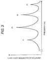
- Fig. 3 is an explanation view showing a vibration characteristic of the railway vehicle use bogie car.
-
- One embodiment of a railway vehicle and a railway vehicle use bogie car according to the present invention will be explained referring to from Fig. 1 to Fig. 3. As shown in Fig. 2, a
bogie frame 11 of a bogie car is supported by twocar axles 13 having avehicle wheel 12 and supports a reduction gear unit which comprises anelectric motor 14 for driving thewheel axles 13 and gears. Thebogie car frame 11 supports acar body 20 through anair cushion member 15. - A connection member 40 (in generally, it is called as a "center pin") which is projected in a lower portion from a lower face of the car body and the
bogie frame 11 are connected according to a traction link 30 (herein, it is called as a "link"). Thelink 30 transmits a before and back force and this link is arranged along to a horizontal direction of a running direction. - End portions of a right and a left of the
bogie frame 11 are connected to thecar body 20 throughyaw dampers yaw damper 28 are connected to thebogie car frame 11 and thecar body 20 through a rubber bush similarly to thelink 30. Theyaw damper 28 can prevent the meandering move during the running time. - Both end portions of the
link 30 are connected to thebogie car 11 and theconnection member 40 through arubber bush 35 and apin 36, etc.. Theconnection member 40 is arranged inclined for directing for a connection portion between from thecar body 20 to thelink 30. A cross-section of a lower end portion of acoupling member 45 of theconnection member 40 is a reversal U shape. Thelink 30 is arranged in the horizontal direction of the running direction of thecar body 20 and penetrates through the above stated U shape portion of thecoupling member 45. The tip end of asecond portion 42 of theconnection member 40 has thecoupling member 45. - To the
bogie frame 11, the U-shapecross-sectional coupling 31 is arranged. Thelink 30 is connected to thecoupling member 31 of thebogie frame 11 and acoupling member 45 of theconnection member 40. This construction has public known technique. - The
connection member 40 has a horizontal cross-section having a quadrilateral shape and using a plate for constituting four faces it is constituted according to a welding manner. Anupper face flange 43 is fixed to a lower face of thecar body 20 through bolt means. An interior portion of the plate for constituting the four faces,reinforcement plates 44 are welded with plural stages in the upper and lower direction. In thereinforce plate 44, ahole 47 is opened in a central portion. - In a space of the interior portion of the
connection member 40, the vibration control use many or a large number ofparticle shape members 50 are accommodated. Theparticle shape members 50 are inserted from an opening which is provided on a side face of theconnection member 40. This opening is sealed with a water-sealed by alid 46 or a sealing agent and the like. Theparticle shape member 50 which has inserted from the upper portion can be dropped down by inclining theconnection member 40. - The
particle shape member 50 is a sphere member using a ferro system or a lead-system material. A particle size ofparticle shape member 50 is 0.1 mm - 10 mm degree. Theparticle shape member 50 is unnecessary to have the sphere shape. In a manufacturing processes, theparticle shape member 50 can be formed using a non-spherical shape member or a multi-angle crushed shape member. - It is preferable to employ a large filling-up density of the
particle shape member 50. When the filling-up density of theparticle shape member 50 is small, the damping effect becomes small, but the filling-up density of theparticle shape member 50 is excessively large the move of theparticle shape member 50 becomes bad and then the vibration control effect is lessened. Further, since a space of the interior portion of theconnection member 40 is large, when the filling-up density of theparticle shape member 50 becomes excessively larger, it invites to the weight increase. - A filling-up amount of the
particle shape member 50 is determined according to the various experimental results. According the to the filling-up amount of theparticle shape member 50, the position of the above stated opening for accommodating theparticle shape member 50 is determined. The amount of theparticle shape member 50 shown in Fig. 1 shows one example. - It is preferable to employ the comparatively large particle size as the
particle shape member 50. For example, the particle size of theparticle shape member 50 can use several mm. When the particle size of theparticle shape member 50 is small as shown in the powder member, the manufacturing cost becomes high. When the particle size of theparticle shape member 50 is large, theparticle shape member 50 can be manufactured with the comparative low cost. - Further, to the anti-corrosion, the corrosion prevention or the abrasion prevention of the
particle shape member 50, an absorption agent (for example, the red ocher and the like), can be enclosed. - With the above stated construction, when the
bogie frame 11 vibrates according to the drive system vibrations, theconnection member 40 vibrates through thelink 30. With this, theparticle shape member 50 accommodated in theconnection member 40 vibrates, and according to the collision of theparticle shape members 50 each other and the collision between the plate of theconnection member 40 and theparticle shape member 50, the vibrations in theconnection member 40 can be reduced and the transmission of the vibrations to thecar body 20 can be reduced. - Further, in proportional to the increase in a specific gravity of the
particle shape member 50, the vibration energy of theconnection member 40 during the collision time is converted to a kinetic energy of theparticle shape member 50 with a good efficiency. Accordingly, the vibration energy becomes small and the vibrations of theconnection member 40 can be reduced. - In particular, according to the vibrations of the drive system, since the move in the before and back direction of the
particle shape member 50 in the interior portion of theconnection member 40 is unnecessary to go against the gravity force (it is unnecessary to have the vibrations of more than 10 m/s2), according to the small excitation force theparticle shape member 50 can be activated. - For this reason, the vibrations in the before and back direction which is solid-propagated to the
car body 20 from theconnection member 40 can be reduced. Accordingly, the vibration in the upper and lower directions on the floor face of thecar body 20 is reduced, the noises in the inner side car which radiates from the floor face of thecar body 20 can be reduced. - Namely, according to the before and back vibrations which solid-propagated through the
link 30, theparticle shape member 50 repeats the collisions with the minute ranges. For this reason, the vibration energy generated to theconnection member 40 is converted to the kinetic energy of theparticle shape member 50. As a result, the vibrations in theconnection member 40 can be reduced. - In comparison with the case where the powder shape member is installed to the floor face of the
car body 20, the reduction of the vibrations in the before and back direction of theconnection member 40. Against the vibrations in the before and back direction of theconnection member 40, even against the small excitation force, the reason why theparticle shape member 50 can move actively (it is unnecessary to have the vibrations of more than 10 m/s2 which goes against the gravity force). - Accordingly, since the before and back vibrations at the
connection member 40 is restrained, the increase in the upper and lower vibrations on the floor face of thecar body 20 can be restrained, and the noises in the inner side car can be reduced. Further, since theconnection member 40 has a comparative light weight, the vibrations can be reduced due to the light weight apparatus. - Further, during the acceleration running time, the deceleration running time and the coasting running time, since the vibrations in the before and back direction increases further, the vibration control effect can be remarkable further. The move of the
particle shape member 50 in this case, against the large excitation force, is moved actively further, the vibration control effect can be increased. - Further, the
particle shape member 50 can be accommodated into the interior portion of thelink 30. As clearly understood from the above stated explanation, it is preferable to make large the weight of theparticle shape member 50. However, since a diameter of thelink 30 is comparatively small, it is preferable to make large the filling-up density of theparticle shape member 50 as soon as possible. However, it is necessary to vibrate theparticle shape member 50 according to the vibrations. Further, to an outer face of thelink 30, a vessel to which theparticle shape member 50 is accommodated can install. - Furthers a longitudinal cross-section shape of the
connection member 40 is formed with substantially L shape. Namely, theconnection member 40 comprises of afirst portion 41 which-extends to a lower portion of the lower face of thecar body 20 and thesecond portion 42 which extends to a horizontal direction in the lower portion of the above statedfirst portion 41. - The
traction link 30 is connected to a tip end of thecoupling member 45 of the second portion 2 of theconnection member 40 which is projected in the horizontal direction. Theparticle shape member 50 is accommodated in the interior portion of thesecond portion 42 of theconnection member 40. - As stated in above, since the
traction link 30 is connected to the horizontally extendedsecond portion 42 of theconnection member 40, thesecond portion 42 of theconnection member 40 can be bent easily in the upper and lower direction. In thissecond portion 42 of theconnection member 40, theparticle shape member 50 is accommodated, then theparticle shape member 50 can be moved actively and the vibrations can be reduced easily. - Further, a lower face of the
second portion 42 of theconnection member 40 is inclined. Accordingly, theparticle shape member 50 can be moved easily and the vibrations can be reduced. - For example, the particle size of the
particle shape member 50 which is accommodated to thelink 30 is 1 mm and the particle size of theparticle shape member 50 which is accommodated to theconnection member 40 is 3 mm which is bigger than that of theparticle shape member 50 accommodated to thelink 30. - With the above stated construction, since by suiting with the characteristics of the respective constituting parts (the
link 30, the connection member 40) theparticle shape member 50 can be accommodated, then the vibration control can performed with the maximum. - Further, to the member of the
bogie frame 11 at the vicinity of the coupling 31 a large number of theparticle shape members 50 are accommodated, and then the transmission of the vibrations to thelink 30 can be lessened. - In the above stated embodiment according to the present invention, the
connection member 40 and thebogie frame 11 are connected according to onetraction link 30, however it can utilize to one in which theconnection member 40 and thebogie frame 11 are connected according to plural traction links. - The technical range of the present invention is not limited to the wordings stated in each claim items of the claims and the wordings stated the items of the means for solving the problems and includes a range in which the man belongs to the technical field can be replaced easily.
- According to the present invention, with a simple construction in which the
particle shape member 50 is accommodated movably to theconnection member 40 for connecting the bogie car and thecar body 20, the transmission of the vibrations which generate from the drive system can be restrained, accordingly the noise in the inner side car can be reduced.
Claims (6)
- A railway vehicle characterized in that
a connection member which is lifted down to a lower face of a car body and a bogie frame are connected according to a traction link and in an interior portion of said connection member a large number of particle shape members are movably accommodated. - A railway vehicle according to claim 1, characterized in thatsaid connection member comprises a first portion which extends to a lower portion from said lower face of said car body and a second portion which extends to a horizontal direction in a lower end portion of said first portion;said traction link is connected to an end portion of said second portion of said connection member; andsaid particle shape member is accommodated in an interior portion of said second portion of said connection member.
- A railway vehicle according to claim 2, characterized in that
a lower face of said second portion of said connection member is inclined. - A railway vehicle use bogie car characterized in that
a connection member which is lifted down to a lower face of a car body and a bogie frame are connected according to a traction link and in an interior portion of said connection member a large number of particle shape members are movably accommodated. - A railway vehicle use bogie car according to claim 4, characterized in thatsaid connection member comprises a first portion which extends to a lower portion from said lower face of said car body and a second portion which extends to a horizontal direction in a lower end portion of said first portion;said traction link is connected to an end portion of said second portion of said connection member; andsaid particle shape member is accommodated in an interior portion of said second portion of said connection member.
- A railway vehicle use bogie car according to claim 5, characterized in that
a lower face of said second portion of said connection member is inclined.
Applications Claiming Priority (2)
| Application Number | Priority Date | Filing Date | Title |
|---|---|---|---|
| JP2000010108 | 2000-01-14 | ||
| JP2000010108 | 2000-01-14 |
Publications (2)
| Publication Number | Publication Date |
|---|---|
| EP1116636A1 true EP1116636A1 (en) | 2001-07-18 |
| EP1116636B1 EP1116636B1 (en) | 2004-08-04 |
Family
ID=18538159
Family Applications (1)
| Application Number | Title | Priority Date | Filing Date |
|---|---|---|---|
| EP00306800A Expired - Lifetime EP1116636B1 (en) | 2000-01-14 | 2000-08-09 | Railway vehicle and railway vehicle use bogie car |
Country Status (5)
| Country | Link |
|---|---|
| US (1) | US6336410B1 (en) |
| EP (1) | EP1116636B1 (en) |
| KR (1) | KR100413262B1 (en) |
| DE (1) | DE60012677T2 (en) |
| TW (1) | TW474876B (en) |
Families Citing this family (2)
| Publication number | Priority date | Publication date | Assignee | Title |
|---|---|---|---|---|
| IN2012DN05112A (en) * | 2010-02-15 | 2015-10-09 | Nippon Sharyo Ltd | |
| FR3088042B1 (en) * | 2018-11-06 | 2020-11-27 | Alstom Transp Tech | BOGIE FOR RAIL VEHICLE |
Citations (4)
| Publication number | Priority date | Publication date | Assignee | Title |
|---|---|---|---|---|
| DE2533088A1 (en) * | 1975-07-24 | 1977-02-03 | Volkswagenwerk Ag | Energy absorbing housing for machining glass - has elastically deformable housing arranged to leave small protrusion of work for grinding |
| WO1985005425A1 (en) * | 1984-05-18 | 1985-12-05 | Saab-Scania Aktiebolag | Device for damping oscillations |
| US4744604A (en) * | 1985-04-08 | 1988-05-17 | Federal-Mogul Corporation | Vibration damping device and a method for a road planer and the like |
| US5775049A (en) * | 1995-06-14 | 1998-07-07 | Fricke; J. Robert | Method and apparatus for damping structural vibrations |
Family Cites Families (4)
| Publication number | Priority date | Publication date | Assignee | Title |
|---|---|---|---|---|
| US3376831A (en) * | 1965-04-27 | 1968-04-09 | Westinghouse Air Brake Co | Hydraulically dampened car bogie |
| CH624061A5 (en) * | 1977-09-20 | 1981-07-15 | Schweizerische Lokomotiv | |
| FR2649949B1 (en) * | 1989-07-18 | 1992-04-24 | Alsthom Gec | ARTICULATED BOGIE FOR RAIL VEHICLES |
| ATE150712T1 (en) * | 1993-10-06 | 1997-04-15 | Abb Daimler Benz Transp | COMPOSITE COMPONENT AS A TENSION-COMPRESSION ROD FOR RAIL VEHICLES |
-
2000
- 2000-07-27 TW TW089115033A patent/TW474876B/en not_active IP Right Cessation
- 2000-08-09 DE DE60012677T patent/DE60012677T2/en not_active Expired - Fee Related
- 2000-08-09 EP EP00306800A patent/EP1116636B1/en not_active Expired - Lifetime
- 2000-08-24 KR KR10-2000-0049202A patent/KR100413262B1/en not_active Expired - Fee Related
- 2000-11-08 US US09/707,819 patent/US6336410B1/en not_active Expired - Fee Related
Patent Citations (4)
| Publication number | Priority date | Publication date | Assignee | Title |
|---|---|---|---|---|
| DE2533088A1 (en) * | 1975-07-24 | 1977-02-03 | Volkswagenwerk Ag | Energy absorbing housing for machining glass - has elastically deformable housing arranged to leave small protrusion of work for grinding |
| WO1985005425A1 (en) * | 1984-05-18 | 1985-12-05 | Saab-Scania Aktiebolag | Device for damping oscillations |
| US4744604A (en) * | 1985-04-08 | 1988-05-17 | Federal-Mogul Corporation | Vibration damping device and a method for a road planer and the like |
| US5775049A (en) * | 1995-06-14 | 1998-07-07 | Fricke; J. Robert | Method and apparatus for damping structural vibrations |
Also Published As
| Publication number | Publication date |
|---|---|
| EP1116636B1 (en) | 2004-08-04 |
| DE60012677D1 (en) | 2004-09-09 |
| KR20010076177A (en) | 2001-08-11 |
| TW474876B (en) | 2002-02-01 |
| US6336410B1 (en) | 2002-01-08 |
| DE60012677T2 (en) | 2005-08-11 |
| KR100413262B1 (en) | 2003-12-31 |
Similar Documents
| Publication | Publication Date | Title |
|---|---|---|
| EP1060970B1 (en) | Connection member for a railway vehicle, to hinder vibration transmission | |
| CN103009980B (en) | Battery support structure for vehicle | |
| CN111907537B (en) | Electric locomotive, electric locomotive bogie and bogie driving system | |
| WO2017219556A1 (en) | Bogie | |
| JP4965131B2 (en) | In-wheel motor | |
| WO2017219555A1 (en) | Frame of bogie | |
| CN103072470A (en) | Electric vehicle powertrain suspension system | |
| CN110667635A (en) | A kind of axle box built-in bogie frame | |
| CN103502085A (en) | Improvements in heavy goods vehicles | |
| EP1116636A1 (en) | Railway vehicle and railway vehicle use bogie car | |
| US20010025737A1 (en) | Vehicle suspension system | |
| EP1116638A1 (en) | Railway vehicle bogie with vibrations reducing device | |
| JP3863358B2 (en) | Railway vehicle | |
| CN114506184A (en) | Vehicle and drive axle device thereof | |
| JP2001206221A (en) | Railcar | |
| JP2001219848A (en) | Railcar | |
| JP2001260878A (en) | Railcar | |
| CN215904269U (en) | AGV three fulcrum electric tractor shock attenuation type transaxles | |
| JP2001219847A (en) | Railcar | |
| CN216579979U (en) | Air spring suspension rear axle housing assembly and engineering truck | |
| CN115556776B (en) | A frame-suspended locomotive drive system and its suspension structure | |
| CN219467743U (en) | A trailer bogie structure | |
| JP4719374B2 (en) | Railway vehicle | |
| JP2002087257A (en) | Railcar | |
| JP2005289370A (en) | Railway vehicle |
Legal Events
| Date | Code | Title | Description |
|---|---|---|---|
| PUAI | Public reference made under article 153(3) epc to a published international application that has entered the european phase |
Free format text: ORIGINAL CODE: 0009012 |
|
| 17P | Request for examination filed |
Effective date: 20000828 |
|
| AK | Designated contracting states |
Kind code of ref document: A1 Designated state(s): DE FR IT |
|
| AX | Request for extension of the european patent |
Free format text: AL;LT;LV;MK;RO;SI |
|
| AKX | Designation fees paid |
Free format text: DE FR IT |
|
| 17Q | First examination report despatched |
Effective date: 20030904 |
|
| GRAP | Despatch of communication of intention to grant a patent |
Free format text: ORIGINAL CODE: EPIDOSNIGR1 |
|
| GRAS | Grant fee paid |
Free format text: ORIGINAL CODE: EPIDOSNIGR3 |
|
| GRAA | (expected) grant |
Free format text: ORIGINAL CODE: 0009210 |
|
| AK | Designated contracting states |
Kind code of ref document: B1 Designated state(s): DE FR IT |
|
| PGFP | Annual fee paid to national office [announced via postgrant information from national office to epo] |
Ref country code: FR Payment date: 20040812 Year of fee payment: 5 |
|
| REF | Corresponds to: |
Ref document number: 60012677 Country of ref document: DE Date of ref document: 20040909 Kind code of ref document: P |
|
| PGFP | Annual fee paid to national office [announced via postgrant information from national office to epo] |
Ref country code: DE Payment date: 20041025 Year of fee payment: 5 |
|
| ET | Fr: translation filed | ||
| PLBE | No opposition filed within time limit |
Free format text: ORIGINAL CODE: 0009261 |
|
| STAA | Information on the status of an ep patent application or granted ep patent |
Free format text: STATUS: NO OPPOSITION FILED WITHIN TIME LIMIT |
|
| 26N | No opposition filed |
Effective date: 20050506 |
|
| PG25 | Lapsed in a contracting state [announced via postgrant information from national office to epo] |
Ref country code: IT Free format text: LAPSE BECAUSE OF NON-PAYMENT OF DUE FEES Effective date: 20050809 |
|
| PG25 | Lapsed in a contracting state [announced via postgrant information from national office to epo] |
Ref country code: DE Free format text: LAPSE BECAUSE OF NON-PAYMENT OF DUE FEES Effective date: 20060301 |
|
| PG25 | Lapsed in a contracting state [announced via postgrant information from national office to epo] |
Ref country code: FR Free format text: LAPSE BECAUSE OF NON-PAYMENT OF DUE FEES Effective date: 20060428 |
|
| REG | Reference to a national code |
Ref country code: FR Ref legal event code: ST Effective date: 20060428 |