EP1115022A2 - Optoelectronic scanning device - Google Patents
Optoelectronic scanning device Download PDFInfo
- Publication number
- EP1115022A2 EP1115022A2 EP00103837A EP00103837A EP1115022A2 EP 1115022 A2 EP1115022 A2 EP 1115022A2 EP 00103837 A EP00103837 A EP 00103837A EP 00103837 A EP00103837 A EP 00103837A EP 1115022 A2 EP1115022 A2 EP 1115022A2
- Authority
- EP
- European Patent Office
- Prior art keywords
- optoelectronic device
- polygon mirror
- coil
- mirror wheel
- magnet
- Prior art date
- Legal status (The legal status is an assumption and is not a legal conclusion. Google has not performed a legal analysis and makes no representation as to the accuracy of the status listed.)
- Granted
Links
Images

Classifications
-
- G—PHYSICS
- G06—COMPUTING; CALCULATING OR COUNTING
- G06K—GRAPHICAL DATA READING; PRESENTATION OF DATA; RECORD CARRIERS; HANDLING RECORD CARRIERS
- G06K7/00—Methods or arrangements for sensing record carriers, e.g. for reading patterns
- G06K7/10—Methods or arrangements for sensing record carriers, e.g. for reading patterns by electromagnetic radiation, e.g. optical sensing; by corpuscular radiation
- G06K7/10544—Methods or arrangements for sensing record carriers, e.g. for reading patterns by electromagnetic radiation, e.g. optical sensing; by corpuscular radiation by scanning of the records by radiation in the optical part of the electromagnetic spectrum
- G06K7/10554—Moving beam scanning
- G06K7/10594—Beam path
- G06K7/10603—Basic scanning using moving elements
- G06K7/10613—Basic scanning using moving elements by rotation, e.g. polygon
-
- G—PHYSICS
- G02—OPTICS
- G02B—OPTICAL ELEMENTS, SYSTEMS OR APPARATUS
- G02B26/00—Optical devices or arrangements for the control of light using movable or deformable optical elements
- G02B26/08—Optical devices or arrangements for the control of light using movable or deformable optical elements for controlling the direction of light
- G02B26/10—Scanning systems
- G02B26/12—Scanning systems using multifaceted mirrors
- G02B26/121—Mechanical drive devices for polygonal mirrors
- G02B26/122—Control of the scanning speed of the polygonal mirror
Definitions
- the invention relates to an optoelectronic device according to the preamble of claim 1.
- Such optoelectronic devices are used to detect marks used, which have defined contrast patterns.
- the optoelectronic device as a barcode reader for reading barcodes be trained.
- the optoelectronic device has a light beam emitting Transmitter and a receiver receiving receiving light rays. There is also a deflection unit with a motor-driven polygon mirror wheel intended. The transmitted light rays and the received light rays are guided over the polygon mirror. By rotating the polygon mirror wheel the transmitted light beams are deflected so that they are periodic paint over an area in which the marks are located.
- the transmitted light beams are over the marks guided. According to the contrast pattern of the brands they point to them received light beams reflect an amplitude modulation.
- the appropriately modulated receive signals at the output of the receiver evaluated in an evaluation unit for the detection of the marks.
- the polygon mirror wheel is driven by a motor, so that the polygon mirror wheel rotates at a predetermined speed.
- motors are usually used for this purpose, in which an engine control is integrated.
- the motor also has a shaft. On the shaft is applied with a mechanical mount on its top the polygon mirror wheel is attached.
- the polygon mirror wheel preferably has For this purpose, a holder on which the receptacle is screwed.
- the motor controller is connected to the evaluation unit via a cable is arranged on a separate circuit board. To contact is at the end of the cable, a connector is provided which in a corresponding socket on the Evaluation unit is inserted.
- deflection unit designed in this way has a large number of electrical and mechanical components.
- the assembly of these components is time consuming and thus represents an undesirably high Cost factor in the manufacture of the optoelectronic device.
- the tolerances of the individually manufactured components mean that Accuracy problems occur with deflection units produced in this way.
- deflection units designed in this way are undesirable large size.
- the invention has for its object a deflection unit for an optoelectronic To create device of the type mentioned, which if possible low manufacturing costs and low manufacturing tolerances has small size.
- the evaluation unit is in the optoelectronic device according to the invention integrated on a printed circuit board, the motor driving the polygon mirror wheel has a shaft opening out on this circuit board which the polygon mirror wheel is rotatably mounted.
- the engine a coil that sits on the circuit board and is connected to it.
- This coil works with one attached to the inside of the polygon mirror wheel Magnets together.
- a major advantage here is that the shaft and the coil of the Motors are attached directly to the circuit board on which the evaluation unit is integrated.
- the motor, in particular the coil, is activated therefore directly via the evaluation unit.
- this can considerably reduce the space required for the deflection unit become. Due to the deflection unit designed in this way, the Size of the entire optoelectronic device can be reduced. In addition, this will also result in a significant reduction in manufacturing costs Device reached.
- the deflection unit has only a small number of Has individual components.
- the manufacturing tolerances in the manufacture of the The deflection unit is accordingly small.
- the deflection unit can be installed quickly and easily.
- the brand 1 shows the basic structure of an optoelectronic device 1 for recognizing marks provided with defined contrast patterns.
- the brands can have any sequence and form of each other adjacent light-dark areas, preferably black and white areas, exhibit.
- the brands of Barcodes 2 formed.
- the barcodes 2 essentially consist of a sequence of black and white line elements 2a, 2b of defined length and width.
- the optoelectronic device 1 is then designed as a barcode reader.
- the optoelectronic device 1 has a transmitting element 3, a receiving element 4 and an evaluation unit 5.
- the transmission element 3 consists of a transmitter 6, preferably a laser diode, and one of the transmitters 6 upstream transmission optics 7 for focusing the transmitted light beams 8. Die focused transmitted light beams 8 are via a rotating polygon mirror wheel 9 deflected and passed over the barcode symbol 2 to be detected.
- the axis of rotation of the polygon mirror wheel 9 is perpendicular to that shown in FIG Equatorial plane of the polygon mirror 9 arranged.
- the transmitted light beams 8 are periodically inside a predetermined angular range within that forming the scanning plane Equatorial level led. You can do this according to the focus of the transmitted light beams 8 bar codes 2 in a predetermined distance range to be read.
- the received light beams 10 reflected by the bar code 2 are transmitted via the Polygon mirror 9 led to the receiving element 4.
- the receiving element 4 consists of a receiver 11, which is formed by a photodiode and in which the received light beams 10 converted into an electrical received signal become.
- An amplifier 12 is connected downstream of the receiver 11.
- the receiving element 4 is receiving optics 13 upstream.
- the received signal at the output of the receiving element 4 becomes supplied to the evaluation unit 5.
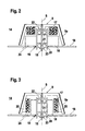
- FIGS. 2 and 3 show two exemplary embodiments of a deflection unit 14, the component of which is the polygon mirror wheel 9 according to FIG. 1. Also includes the deflection unit 14 is a motor by means of which the polygon mirror wheel 9 is driven is so that it rotates at a predetermined speed executes.
- This motor comprises a shaft 15 on which the polygon mirror wheel 9 is rotatably mounted, as well as a coil 16 and one interacting with it Magnet 17.
- the shaft 15 opens out on a circuit board 18 on which the evaluation unit 5 is integrated.
- the longitudinal axis of the shaft 15 is perpendicular to the surface of the circuit board 18.
- the coil 16 is seated on this circuit board 18 on.
- the magnet 17 is attached to the polygon mirror wheel 9 and rotates with it this with.
- a current is fed into the coil 16 via the evaluation unit 5, whereby a magnetic field is generated in the coil 16, through which the magnet 17 and thus the polygon mirror 9 is rotated becomes.
- the electronic components of the evaluation unit are on the printed circuit board 18 5 arranged, these for the sake of clarity in Figures 2 and 3 are not shown.
- a bore 19 is in the center of the printed circuit board 18 intended.
- a tube 20 is mounted, which is from the circuit board 18 protrudes vertically.
- the tube 20 consists of a hollow cylindrical Plastic part, the top and bottom of which are open. Alternatively the tube 20 can consist of metal.
- the shaft 15 runs inside the tube 20, the shaft 15 via bearings 21 is mounted on the inner wall of the tube 20.
- the shaft 15 runs in the longitudinal direction of the tube 20 along its axis of symmetry S.
- the bearings 21 can in particular be designed as a ball bearing, plain bearing or roller bearing.
- the Shaft 15 rotates according to the speed specified above the motor around the axis of symmetry S and the polygon mirror wheel attached to it 9 in a corresponding rotary movement.
- the polygon mirror 9 is in the illustrated embodiments of a molded plastic part.
- This polygon mirror wheel 9 is inclined side walls tapering to a flat ceiling.
- the outside of the side walls of the polygon mirror wheel 9 are coated with a reflective layer and form the mirror surfaces 9a on which the transmitted light beams 8 to get distracted.
- the ceiling and the side walls delimit a cavity inside the polygon mirror wheel 9, which is open at the bottom.
- the tube 20 with the shaft 15 supported therein projects from the underside into the cavity of the polygon mirror wheel 9.
- the shaft 15 protrudes over the upper end of the tube 20.
- the upper free end of the shaft 15 is with the ceiling of the polygon mirror 9th rigidly connected.
- the ceiling of the polygon mirror wheel 9 is in its center widened towards the bottom. In this broadening there is one in the symmetry axis S of the polygon mirror wheel 9 extending and at the bottom of the Cover opening 22 provided in the free end of the shaft 15 is pressed.
- the shaft can also be designed as an insert, which at the production of the molded plastic part is encapsulated with plastic.
- the shaft 15 is fixed with a clamp closure 23.
- the polygon mirror wheel 9 is thus symmetrical to that of the axis of symmetry S formed axis of rotation, in which the shaft 15 is arranged, wherein the side walls of the polygon mirror wheel 9 at a predetermined distance from the tube 20 run.
- the overall heights of the shaft 15 and the tube 20 are based on the overall height of the polygon mirror wheel 9 adjusted so that the lower edges of the side walls of the Polygon mirror 9 run closely above the circuit board 18. It is however, the distance chosen is so large that it rotates when the polygon mirror 9 not arranged for contact with the printed circuit board 18 or thereon Components is coming.
- the coil 16 lies against the outside of the tube 20.
- the coil 16 is there arranged rotationally symmetrical to the axis of rotation of the shaft 15 and sits on a not shown coil core.
- the tube 20 is preferably on the Printed circuit board 18 pressed in while the coil 16 and the coil core for fixation are stuck.
- connection means 24 are formed by wires that run from the Coil 16 are guided to the evaluation unit 5. Via the connection means 24 the evaluation unit 5 feeds the current into the coil 16, which generates the magnetic field that the magnet 17 and the polygon mirror 9 in rotated.
- the magnet 17 on the polygon mirror 9 on the inside of the Ceiling and / or the side walls are provided, preferably in one piece with the plastic injection molding forming the polygon mirror wheel 9 are trained.
- the magnet 17 is expediently attached to the receptacles glued on.
- the magnet 17 and the coil 16 each formed as disks, which have a circular cross section exhibit.
- the coil 16 and the magnet 17 are one above the other arranged lying so that the top of the coil 16 the bottom of the magnet 17 are at a short distance from each other.
- the coil 16 and the magnet 17 each have an axially penetrating them central opening. These openings have approximately the same diameter and run coaxially and symmetrically to the axes of symmetry of the magnet 17 and the coil 16 with the axis of symmetry S of the polygon mirror 9 collapse. Inside the openings, the tube 20 runs with the shaft 15 mounted therein while coil 16 is on the outside of the tube 20 is tight, the distance of the magnet 17 to the outer wall of the tube 20 slightly larger, so that friction of the magnet 17 on the tube 20 during the rotation of the polygon mirror wheel 9 is excluded.
- the outer diameter of the disc-shaped magnet 17 and the correspondingly designed coil 16 are substantially the same size and adapted to the inside diameter of the polygon mirror wheel 9.
- the magnet 17 and the coil 16 thus fill almost the entire space between the inside of the side walls of the polygon mirror wheel 9 and the tube 20 out.
- the magnet 17 is on the ceiling of the polygon mirror wheel 9 attached.
- the magnet 17 is locked.
- the magnet 17 glued to the ceiling of the polygon mirror 9 become.
- the magnet 17 and the coil 16 is each annular.
- the coil 16 is in the form of a formed the first ring which surrounds the tube 20.
- the magnet 17 is in Formed a second ring, coaxial with the first, from the coil 16 formed ring is arranged.
- the outer surface lies of the first ring formed by the coil 16 and the inner surface of the opposite the second ring formed by the magnet 17 at a short distance, so that when the polygon mirror wheel 9 rotates, there is no friction between the magnet 17 and the coil 16 strikes.
- the annular coil 16 extends over almost the entire height of the tube 20.
- the overall height of the annular magnet 17 corresponds essentially the overall height of the annular coil 16, so that almost the entire lateral surfaces of the magnet 17 and the coil 16 are opposite each other.
- the annular magnet 17 is included its outer surface on the inside of the side walls of the polygon mirror 9 attached.
- To attach the magnet 17 are from the inside of the side walls as webs 25 formed recordings which the magnet 17 can be attached by locking means.
- the magnet 17 can be glued to the webs 25.
Abstract
Description
Die Erfindung betrifft eine optoelektronische Vorrichtung gemäß dem Oberbegriff
des Anspruchs 1.The invention relates to an optoelectronic device according to the preamble
of
Derartige optoelektronische Vorrichtungen werden zur Erfassung von Marken eingesetzt, welche definierte Kontrastmuster aufweisen. Insbesondere kann die optoelektronische Vorrichtung als Barcodelesegerät zum Lesen von Barcodes ausgebildet sein.Such optoelectronic devices are used to detect marks used, which have defined contrast patterns. In particular, the optoelectronic device as a barcode reader for reading barcodes be trained.
Die optoelektronische Vorrichtung weist einen Sendelichtstrahlen emittierenden Sender sowie einen Empfangslichtstrahlen empfangenden Empfänger auf. Zudem ist eine Ablenkeinheit mit einem motorisch angetriebenen Polygonspiegelrad vorgesehen. Die Sendelichtstrahlen und die Empfangslichtstrahlen werden über das Polygonspiegelrad geführt. Durch die Drehbewegung des Polygonspiegelrads werden die Sendelichtstrahlen abgelenkt, so dass diese periodisch einen Raumbereich überstreichen, in welchem sich die Marken befinden.The optoelectronic device has a light beam emitting Transmitter and a receiver receiving receiving light rays. There is also a deflection unit with a motor-driven polygon mirror wheel intended. The transmitted light rays and the received light rays are guided over the polygon mirror. By rotating the polygon mirror wheel the transmitted light beams are deflected so that they are periodic paint over an area in which the marks are located.
Bei der Abtastung der Marken werden die Sendelichtstrahlen über die Marken geführt. Entsprechend dem Kontrastmuster der Marken weisen die an diesen zurückreflektierten Empfangslichtstrahlen eine Amplitudenmodulation auf. Die entsprechend modulierten Empfangssignale am Ausgang des Empfängers werden in einer Auswerteeinheit zur Erfassung der Marken ausgewertet.When scanning the marks, the transmitted light beams are over the marks guided. According to the contrast pattern of the brands they point to them received light beams reflect an amplitude modulation. The appropriately modulated receive signals at the output of the receiver evaluated in an evaluation unit for the detection of the marks.
Das Polygonspiegelrad wird mittels eines Motors angetrieben, so dass das Polygonspiegelrad mit einer vorgegebenen Drehzahl eine Drehbewegung ausführt. Üblicherweise werden hierzu handelsübliche Motoren eingesetzt, in welchen eine Motorsteuerung integriert ist. Zudem weist der Motor eine Welle auf. Auf die Welle wird eine mechanische Aufnahme aufgebracht, auf deren Oberseite das Polygonspiegelrad befestigt wird. Vorzugsweise weist das Polygonspiegelrad hierzu eine Halterung auf, an welcher die Aufnahme festgeschraubt wird. Die Motorsteuerung ist über ein Kabel mit der Auswerteeinheit verbunden, die auf einer separaten Leiterplatte angeordnet ist. Zur Kontaktierung ist am Ende des Kabels ein Stecker vorgesehen, der in eine entsprechende Buchse an der Auswerteeinheit eingesteckt wird.The polygon mirror wheel is driven by a motor, so that the polygon mirror wheel rotates at a predetermined speed. Commercially available motors are usually used for this purpose, in which an engine control is integrated. The motor also has a shaft. On the shaft is applied with a mechanical mount on its top the polygon mirror wheel is attached. The polygon mirror wheel preferably has For this purpose, a holder on which the receptacle is screwed. The motor controller is connected to the evaluation unit via a cable is arranged on a separate circuit board. To contact is at the end of the cable, a connector is provided which in a corresponding socket on the Evaluation unit is inserted.
Nachteilig hierbei ist, dass eine derartig ausgebildete Ablenkeinheit eine Vielzahl von elektrischen und mechanischen Komponenten aufweist. Die Montage dieser Komponenten ist zeitaufwendig und stellt damit einen unerwünscht hohen Kostenfaktor bei der Fertigung der optoelektronischen Vorrichtung dar. Zudem führen die Toleranzen der einzeln gefertigten Komponenten dazu, dass Genauigkeitsprobleme bei derartig hergestellten Ablenkeinheiten auftreten. Schließlich weisen derartig ausgebildete Ablenkeinheiten eine unerwünscht große Baugröße auf.The disadvantage here is that a deflection unit designed in this way has a large number of electrical and mechanical components. The assembly of these components is time consuming and thus represents an undesirably high Cost factor in the manufacture of the optoelectronic device. In addition, the tolerances of the individually manufactured components mean that Accuracy problems occur with deflection units produced in this way. Finally, deflection units designed in this way are undesirable large size.
Der Erfindung liegt die Aufgabe zugrunde, eine Ablenkeinheit für eine optoelektronische Vorrichtung der eingangs genannten Art zu schaffen, die bei möglichst geringen Fertigungskosten und geringen Fertigungstoleranzen eine möglichst geringe Baugröße aufweist.The invention has for its object a deflection unit for an optoelectronic To create device of the type mentioned, which if possible low manufacturing costs and low manufacturing tolerances has small size.
Zur Lösung dieser Aufgabe sind die Merkmale des Anspruchs 1 vorgesehen.
Vorteilhafte Ausführungsformen und zweckmäßige Weiterbildungen der Erfindung
sind in den Unteransprüchen beschrieben.The features of
Bei der erfindungsgemäßen optoelektronischen Vorrichtung ist die Auswerteeinheit auf einer Leiterplatte integriert, wobei der Motor zum Antrieb des Polygonspiegelrads eine an dieser Leiterplatte ausmündende Welle aufweist, an welcher das Polygonspiegelrad drehbar gelagert ist. Zudem weist der Motor eine Spule auf, die auf der Leiterplatte aufsitzt und an diese angeschlossen ist. The evaluation unit is in the optoelectronic device according to the invention integrated on a printed circuit board, the motor driving the polygon mirror wheel has a shaft opening out on this circuit board which the polygon mirror wheel is rotatably mounted. In addition, the engine a coil that sits on the circuit board and is connected to it.
Diese Spule wirkt mit einem an der Innenseite des Polygonspiegelrads befestigten Magneten zusammen.This coil works with one attached to the inside of the polygon mirror wheel Magnets together.
Ein wesentlicher Vorteil hierbei besteht darin, dass die Welle und die Spule des Motors direkt an der Leiterplatte angebracht sind, auf welcher die Auswerteeinheit integriert ist. Die Ansteuerung des Motors, insbesondere der Spule erfolgt daher direkt über die Auswerteeinheit.A major advantage here is that the shaft and the coil of the Motors are attached directly to the circuit board on which the evaluation unit is integrated. The motor, in particular the coil, is activated therefore directly via the evaluation unit.
Damit entfällt eine separate Motorsteuerung und ebenfalls eine elektrische Verbindung zwischen einer solchen Motorsteuerung und der Auswerteeinheit mittels eines Kabels und eines Steckers.This eliminates the need for a separate motor control and also an electrical one Connection between such a motor control and the evaluation unit by means of a cable and a plug.
Dadurch kann zum einen der Platzbedarf der Ablenkeinheit erheblich verringert werden. Durch die so ausgebildete Ablenkeinheit kann insbesondere auch die Baugröße der gesamten optoelektronischen Vorrichtung verkleinert werden. Zudem wird dadurch auch eine erhebliche Reduktion der Herstellkosten der Vorrichtung erreicht.On the one hand, this can considerably reduce the space required for the deflection unit become. Due to the deflection unit designed in this way, the Size of the entire optoelectronic device can be reduced. In addition, this will also result in a significant reduction in manufacturing costs Device reached.
Schließlich ist vorteilhaft, dass die Ablenkeinheit nur eine geringe Anzahl von Einzelkomponenten aufweist. Die Fertigungstoleranzen bei der Fertigung der Ablenkeinheit sind dementsprechend gering. Zudem kann die Ablenkeinheit schnell und einfach montiert werden.Finally, it is advantageous that the deflection unit has only a small number of Has individual components. The manufacturing tolerances in the manufacture of the The deflection unit is accordingly small. In addition, the deflection unit can be installed quickly and easily.
Die Erfindung wird im nachstehenden anhand der Zeichnungen erläutert. Es zeigen:
- Figur 1:
- Prinzipaufbau einer als Barcodelesegerät ausgebildeten optoelektronischen Vorrichtung.
- Figur 2:
- Erstes Ausführungsbeispiel einer Ablenkeinheit für die Vorrichtung
gemäß
Figur 1. - Figur 3:
- Zweites Ausführungsbeispiel einer Ablenkeinheit für die Vorrichtung
gemäß
Figur 1.
- Figure 1:
- Principle structure of an optoelectronic device designed as a barcode reader.
- Figure 2:
- First exemplary embodiment of a deflection unit for the device according to FIG. 1.
- Figure 3:
- Second exemplary embodiment of a deflection unit for the device according to FIG. 1.
In Figur 1 ist der prinzipielle Aufbau einer optoelektronischen Vorrichtung 1
zum Erkennen von mit definierten Kontrastmustern versehenen Marken dargestellt.
Prinzipiell können die Marken beliebige Folgen und Formen von aneinander
angrenzenden Hell-Dunkelflächen, vorzugsweise Schwarz-Weiß-Flächen,
aufweisen. Im vorliegenden Ausführungsbeispiel sind die Marken von
Barcodes 2 gebildet. Die Barcodes 2 bestehen im wesentlichen aus einer Folge
von schwarzen und weißen Strichelementen 2a, 2b definierter Länge und Breite.
Die optoelektronische Vorrichtung 1 ist dann als Barcodelesegerät ausgebildet.1 shows the basic structure of an
Die optoelektronische Vorrichtung 1 weist ein Sendeelement 3, ein Empfangselement
4 sowie eine Auswerteeinheit 5 auf. Das Sendeelement 3 besteht aus
einem Sender 6, vorzugsweise einer Laserdiode, sowie aus einer dem Sender 6
vorgeschalteten Sendeoptik 7 zur Fokussierung der Sendelichtstrahlen 8. Die
fokussierten Sendelichtstrahlen 8 werden über ein rotierendes Polygonspiegelrad
9 abgelenkt und über das zu detektierende Barcode-Symbol 2 geführt. Die
Drehachse des Polygonspiegelrads 9 ist senkrecht zur in Figur 2 dargestellten
Äquatorialebene des Polygonspiegelrads 9 angeordnet. Durch die Drehbewegung
des Polygonspiegelrads 9 werden die Sendelichtstrahlen 8 periodisch innerhalb
eines vorgegebenen Winkelbereichs innerhalb der die Abtastebene bildenden
Äquatorialebene geführt. Dabei können entsprechend der Fokussierung
der Sendelichtstrahlen 8 Barcodes 2 in einem vorgegebenen Distanzbereich
gelesen werden.The
Bei dem in Figur 1 dargestellten Ausführungsbeispiel weist das Polygonspiegelrad
9 acht Spiegelflächen 9a in Form von Facetten auf, an welchen die Sendelichtstrahlen
8 abgelenkt werden. Entsprechend der Anzahl der Facetten des
Polygonspiegelrads 9 wird von den Sendelichtstrahlen 8 periodisch ein Winkelbereich
von Δα = 90° überstrichen, wobei die Abtastebene, in der die Sendelichtstrahlen
8 geführt sind, entsprechend der Anordnung gemäß Figur 1 in
der Äquatorialebene des Polygonspiegelrads 9 liegt.In the embodiment shown in Figure 1, the polygon mirror wheel
9 eight
Die vom Barcode 2 reflektierten Empfangslichtstrahlen 10 werden über das
Polygonspiegelrad 9 zum Empfangselement 4 geführt. Das Empfangselement 4
besteht aus einem Empfänger 11, der von einer Fotodiode gebildet ist und in
dem die Empfangslichtstrahlen 10 in ein elektrisches Empfangssignal gewandelt
werden. Dem Empfänger 11 ist ein Verstärker 12 nachgeschaltet. Zur Verbesserung
der Nachweisempfindlichkeit ist dem Empfangselement 4 eine Empfangsoptik
13 vorgeschaltet.The received
Das am Ausgang des Empfangselements 4 anstehende Empfangssignal wird
der Auswerteeinheit 5 zugeführt.The received signal at the output of the receiving element 4 becomes
supplied to the
Entsprechend dem Kontrastmuster des Barcodes 2 weisen die an diesem reflektierten
Empfangslichtstrahlen 10 eine Amplitudenmodulation auf. Das
durch die Empfangslichtstrahlen 10 am Ausgang des Empfängers 11 anstehende
Empfangssignal weist eine entsprechende Amplitudenmodulation auf. In der
Auswerteeinheit 5 wird anhand der Amplitudenmodulation des Empfangssignals
das Kontrastmuster des Barcodes 2 rekonstruiert.Corresponding to the contrast pattern of the
Die Figuren 2 und 3 zeigen zwei Ausführungsbeispiele einer Ablenkeinheit 14,
deren Bestandteil das Polygonspiegelrad 9 gemäß Figur 1 ist. Zudem umfasst
die Ablenkeinheit 14 einen Motor, mittels dessen das Polygonspiegelrad 9 angetrieben
wird, so dass dieses mit einer vorgegebenen Drehzahl eine Drehbewegung
ausführt. Dieser Motor umfasst eine Welle 15, an der das Polygonspiegelrad
9 drehbar gelagert ist, sowie eine Spule 16 und einen mit dieser zusammenwirkenden
Magneten 17.FIGS. 2 and 3 show two exemplary embodiments of a
Die Welle 15 mündet an einer Leiterplatte 18 aus, auf welcher die Auswerteeinheit
5 integriert ist. Die Längsachse der Welle 15 verläuft dabei senkrecht
zur Oberfläche der Leiterplatte 18. Die Spule 16 sitzt auf dieser Leiterplatte 18
auf. Der Magnet 17 ist an dem Polygonspiegelrad 9 befestigt und dreht sich mit
diesem mit. Über die Auswerteeinheit 5 wird in die Spule 16 ein Strom eingespeist,
wodurch in der Spule 16 ein Magnetfeld erzeugt wird, durch welches
der Magnet 17 und damit das Polygonspiegelrad 9 in eine Drehbewegung versetzt
wird.The
Auf der Leiterplatte 18 sind die elektronischen Bauelemente der Auswerteeinheit
5 angeordnet, wobei diese der Übersichtlichkeit halber in den Figuren 2
und 3 nicht dargestellt sind. Im Zentrum der Leiterplatte 18 ist eine Bohrung 19
vorgesehen. In dieser Bohrung 19 ist ein Tubus 20 gelagert, der von der Leiterplatte
18 senkrecht hervorsteht. Der Tubus 20 besteht aus einem hohlzylindrischen
Kunststoffteil, dessen Oberseite und Unterseite offen sind. Alternativ
kann der Tubus 20 aus Metall bestehen.The electronic components of the evaluation unit are on the printed
Im Innern des Tubus 20 verläuft die Welle 15, wobei die Welle 15 über Lager
21 an der Innenwand des Tubus 20 gelagert ist. Die Welle 15 verläuft in Längsrichtung
des Tubus 20 entlang dessen Symmetrieachse S. Die Lager 21 können
insbesondere als Kugellager, Gleitlager oder Rollenlager ausgebildet sein. Die
Welle 15 dreht sich entsprechend der über dem Motor vorgegebenen Drehzahl
um die Symmetrieachse S und versetzt das daran befestigte Polygonspiegelrad
9 in eine entsprechende Drehbewegung.The
Das Polygonspiegelrad 9 ist in den dargestellten Ausführungsbeispielen von
einem Kunststoffspritzteil gebildet. Dieses Polygonspiegelrad 9 weist schräg
auf eine ebene Decke zulaufende Seitenwände auf. Die Außenseiten der Seitenwände
des Polygonspiegelrads 9 sind mit einer spiegelnden Schicht beschichtet
und bilden die Spiegelflächen 9a, an welchen die Sendelichtstrahlen 8
abgelenkt werden.The polygon mirror 9 is in the illustrated embodiments of
a molded plastic part. This polygon mirror wheel 9 is inclined
side walls tapering to a flat ceiling. The outside of the side walls
of the polygon mirror wheel 9 are coated with a reflective layer
and form the mirror surfaces 9a on which the transmitted
Die Decke und die Seitenwände begrenzen einen Hohlraum im Innern des Polygonspiegelrads
9, welches an der Unterseite offen ist. Der Tubus 20 mit der
darin gelagerten Welle 15 ragt von der Unterseite in den Hohlraum des Polygonspiegelrads
9. Die Welle 15 steht über das obere Ende des Tubus 20 hervor.
Das obere freie Ende der Welle 15 ist mit der Decke des Polygonspiegelrads 9
starr verbunden. Hierzu ist die Decke des Polygonspiegelrads 9 in ihrem Zentrum
zur Unterseite hin verbreitert. In dieser Verbreiterung ist eine in der Symmetrieachse
S des Polygonspiegelrads 9 verlaufende und an der Unterseite der
Decke ausmündende Bohrung 22 vorgesehen, in die das freie Ende der Welle
15 eingepresst ist. Falls das Polygonspiegelrad von einem Kunststoffspritzteil
gebildet ist, kann die Welle auch als Einlegeteil ausgebildet sein, welches bei
der Herstellung des Kunststoffspritzteils mit Kunststoff umspritzt wird.The ceiling and the side walls delimit a cavity inside the polygon mirror wheel
9, which is open at the bottom. The
An der Unterseite des 20 ist die Welle 15 mit einem Klemmverschluss 23 fixiert.
Das Polygonspiegelrad 9 ist somit symmetrisch zu der von der Symmetrieachse
S gebildeten Drehachse, in der die Welle 15 liegt, angeordnet, wobei
die Seitenwände des Polygonspiegelrads 9 in vorgegebenem Abstand zum Tubus
20 verlaufen.On the underside of the 20, the
Die Bauhöhen der Welle 15 und des Tubus 20 sind an die Bauhöhe des Polygonspiegelrads
9 angepasst, so dass die unteren Ränder der Seitenwände des
Polygonspiegelrads 9 dicht oberhalb der Leiterplatte 18 verlaufen. Dabei ist
jedoch der Abstand so groß gewählt, dass es bei der Drehung des Polygonspiegelrads
9 nicht zu einem Kontakt mit der Leiterplatte 18 oder darauf angeordneten
Bauelementen kommt.The overall heights of the
Die Spule 16 liegt an der Außenseite des Tubus 20 an. Die Spule 16 ist dabei
rotationssymmetrisch zur Drehachse der Welle 15 angeordnet und sitzt auf einem
nicht dargestellten Spulenkern auf. Vorzugsweise ist der Tubus 20 an der
Leiterplatte 18 eingepresst, während die Spule 16 und der Spulenkern zur Fixierung
festgeklebt sind.The
Die Spule 16 ist über Anschlussmittel 24 mit der Leiterplatte 18 verbunden. Im
einfachsten Fall sind die Anschlussmittel 24 von Drähten gebildet, die von der
Spule 16 auf die Auswerteeinheit 5 geführt sind. Über die Anschlussmittel 24
wird von der Auswerteeinheit 5 der Strom in die Spule 16 eingespeist, welcher
das Magnetfeld erzeugt, das den Magneten 17 und das Polygonspiegelrad 9 in
eine Drehbewegung versetzt.The
Zur Fixierung des Magneten 17 am Polygonspiegelrad 9 an den Innenseiten der
Decke und/oder der Seitenwände sind Aufnahmen vorgesehen, die vorzugsweise
einstückig mit dem das Polygonspiegelrad 9 bildenden Kunststoffspritzteil
ausgebildet sind. Zweckmäßigerweise wird der Magnet 17 an den Aufnahmen
festgeklebt.To fix the
Bei dem in Figur 2 dargestellten Ausführungsbeispiel sind der Magnet 17 und
die Spule 16 jeweils als Scheiben ausgebildet, die einen kreisförmigen Querschnitt
aufweisen. Dabei sind die Spule 16 und der Magnet 17 übereinander
liegend angeordnet, so dass die Oberseite der Spule 16 der Unterseite des Magneten
17 in geringem Abstand gegenüber liegen.In the embodiment shown in Figure 2, the
Die Spule 16 und der Magnet 17 weisen jeweils eine diese axial durchsetzende
zentrale Öffnung auf. Diese Öffnungen weisen etwa denselben Durchmesser
auf und verlaufen koaxial und symmetrisch zu den Symmetrieachsen des Magneten
17 und der Spule 16, die mit der Symmetrieachse S des Polygonspiegelrads
9 zusammenfallen. Im Innern der Öffnungen verläuft der Tubus 20 mit der
darin gelagerten Welle 15. Während die Spule 16 an der Außenseite des Tubus
20 dicht anliegt, ist der Abstand des Magneten 17 zur Außenwand des Tubus
20 etwas größer, so dass eine Reibung des Magneten 17 am Tubus 20 während
der Drehung des Polygonspiegelrads 9 ausgeschlossen ist.The
Die Außendurchmesser des scheibenförmig ausgebildeten Magneten 17 und
der entsprechend ausgebildeten Spule 16 sind im wesentlichen gleich groß und
an den Innendurchmesser des Polygonspiegelrads 9 angepasst. Der Magnet 17
und die Spule 16 füllen somit nahezu den gesamten Zwischenraum zwischen
den Innenseiten der Seitenwände des Polygonspiegelrads 9 und dem Tubus 20
aus. The outer diameter of the disc-shaped
Der Magnet 17 ist in diesem Ausführungsbeispiel an der Decke des Polygonspiegelrads
9 befestigt. Zur Fixierung des Magneten 17 können an der Innenseite
der Decke Aufnahmen in Form von nicht dargestellten Vertiefungen vorgesehen
sein, in welche der Magnet 17 eingerastet wird. Zusätzlich oder alternativ
kann der Magnet 17 an der Decke des Polygonspiegelrads 9 festgeklebt
werden.In this exemplary embodiment, the
Bei dem in Figur 3 dargestellten Ausführungsbeispiel sind der Magnet 17 und
die Spule 16 jeweils ringförmig ausgebildet. Die Spule 16 ist in Form eines
ersten Ringes ausgebildet, der den Tubus 20 umschließt. Der Magnet 17 ist in
Form eines zweiten Ringes ausgebildet, der koaxial zum ersten, von der Spule
16 gebildeten Ring angeordnet ist. Dabei liegen sich die äußere Mantelfläche
des von der Spule 16 gebildeten ersten Rings und die innere Mantelfläche des
von dem Magneten 17 gebildeten zweiten Rings in geringem Abstand gegenüber,
so dass bei der Drehung des Polygonspiegelrads 9 keine Reibung zwischen
dem Magneten 17 und der Spule 16 auftrifft.In the embodiment shown in Figure 3, the
Die ringförmige Spule 16 erstreckt sich über nahezu die gesamte Höhe des Tubus
20. Die Bauhöhe des ringförmigen Magneten 17 entspricht im wesentlichen
der Bauhöhe der ringförmigen Spule 16, so dass nahezu die gesamten Mantelflächen
des Magneten 17 und der Spule 16 einander gegenüber liegen.The
Bei dem Ausführungsbeispiel gemäß Figur 3 ist der ringförmige Magnet 17 mit
seiner äußeren Mantelfläche an den Innenseiten der Seitenwände des Polygonspiegelrads
9 befestigt. Zur Befestigung des Magneten 17 stehen von den Innenseiten
der Seitenwände als Stege 25 ausgebildete Aufnahmen hervor, an
welchen der Magnet 17 durch Rastmittel befestigt werden kann. Alternativ oder
zusätzlich kann der Magnet 17 an den Stegen 25 festgeklebt werden.In the exemplary embodiment according to FIG. 3, the
Claims (21)
Applications Claiming Priority (2)
| Application Number | Priority Date | Filing Date | Title |
|---|---|---|---|
| DE10000445 | 2000-01-07 | ||
| DE2000100445 DE10000445C2 (en) | 2000-01-07 | 2000-01-07 | Optoelectronic device |
Publications (3)
| Publication Number | Publication Date |
|---|---|
| EP1115022A2 true EP1115022A2 (en) | 2001-07-11 |
| EP1115022A3 EP1115022A3 (en) | 2004-06-02 |
| EP1115022B1 EP1115022B1 (en) | 2006-11-22 |
Family
ID=7626936
Family Applications (1)
| Application Number | Title | Priority Date | Filing Date |
|---|---|---|---|
| EP20000103837 Expired - Lifetime EP1115022B1 (en) | 2000-01-07 | 2000-02-24 | Optoelectronic scanning device |
Country Status (2)
| Country | Link |
|---|---|
| EP (1) | EP1115022B1 (en) |
| DE (2) | DE10000445C2 (en) |
Cited By (3)
| Publication number | Priority date | Publication date | Assignee | Title |
|---|---|---|---|---|
| EP1923819A1 (en) | 2006-11-18 | 2008-05-21 | Leuze electronic GmbH + Co. KG | Bar code reader |
| EP3035102A1 (en) * | 2014-12-17 | 2016-06-22 | Shinano Kenshi Kabushiki Kaisha | Rotary body driving apparatus |
| US9515533B2 (en) | 2014-11-26 | 2016-12-06 | Shinano Kenshi Kabushiki Kaisha | Rotary body driving apparatus |
Citations (9)
| Publication number | Priority date | Publication date | Assignee | Title |
|---|---|---|---|---|
| JPS59197010A (en) * | 1983-04-25 | 1984-11-08 | Canon Inc | Information recorder |
| JPS60123819A (en) * | 1983-12-08 | 1985-07-02 | Copal Denshi Kk | Rotary mirror and its working device |
| JPS6227713A (en) * | 1985-07-30 | 1987-02-05 | Canon Inc | Rotating polygonal mirror scanner |
| EP0260156A1 (en) * | 1986-09-12 | 1988-03-16 | Spectra-Physics, Inc. | Bar code scanner with DC brushless motor |
| EP0294219A2 (en) * | 1987-06-04 | 1988-12-07 | Konica Corporation | Polygon mirror |
| US4836631A (en) * | 1985-07-23 | 1989-06-06 | Kanegafuchi Chemical Industry Co., Ltd. | Laser scanning motor having a rotating polygonal mirror and method of manufacturing the same |
| US5103335A (en) * | 1989-05-23 | 1992-04-07 | Canon Kabushiki Kaisha | Motor device having a dynamic-pressure fluid bearing |
| US5479201A (en) * | 1990-04-06 | 1995-12-26 | Canon Kabushiki Kaisha | Optical beam scanner with circuit board mounted elements |
| US5999301A (en) * | 1997-07-16 | 1999-12-07 | Microscan Systems Incorporated | Optical scanning device |
-
2000
- 2000-01-07 DE DE2000100445 patent/DE10000445C2/en not_active Expired - Lifetime
- 2000-02-24 EP EP20000103837 patent/EP1115022B1/en not_active Expired - Lifetime
- 2000-02-24 DE DE50013771T patent/DE50013771D1/en not_active Expired - Lifetime
Patent Citations (9)
| Publication number | Priority date | Publication date | Assignee | Title |
|---|---|---|---|---|
| JPS59197010A (en) * | 1983-04-25 | 1984-11-08 | Canon Inc | Information recorder |
| JPS60123819A (en) * | 1983-12-08 | 1985-07-02 | Copal Denshi Kk | Rotary mirror and its working device |
| US4836631A (en) * | 1985-07-23 | 1989-06-06 | Kanegafuchi Chemical Industry Co., Ltd. | Laser scanning motor having a rotating polygonal mirror and method of manufacturing the same |
| JPS6227713A (en) * | 1985-07-30 | 1987-02-05 | Canon Inc | Rotating polygonal mirror scanner |
| EP0260156A1 (en) * | 1986-09-12 | 1988-03-16 | Spectra-Physics, Inc. | Bar code scanner with DC brushless motor |
| EP0294219A2 (en) * | 1987-06-04 | 1988-12-07 | Konica Corporation | Polygon mirror |
| US5103335A (en) * | 1989-05-23 | 1992-04-07 | Canon Kabushiki Kaisha | Motor device having a dynamic-pressure fluid bearing |
| US5479201A (en) * | 1990-04-06 | 1995-12-26 | Canon Kabushiki Kaisha | Optical beam scanner with circuit board mounted elements |
| US5999301A (en) * | 1997-07-16 | 1999-12-07 | Microscan Systems Incorporated | Optical scanning device |
Non-Patent Citations (3)
| Title |
|---|
| PATENT ABSTRACTS OF JAPAN vol. 009, no. 062 (P-342), 19. März 1985 (1985-03-19) -& JP 59 197010 A (CANON KK), 8. November 1984 (1984-11-08) * |
| PATENT ABSTRACTS OF JAPAN vol. 009, no. 281 (P-403), 8. November 1985 (1985-11-08) -& JP 60 123819 A (KOPARU DENSHI KK), 2. Juli 1985 (1985-07-02) * |
| PATENT ABSTRACTS OF JAPAN vol. 011, no. 207 (P-592), 4. Juli 1987 (1987-07-04) -& JP 62 027713 A (CANON INC), 5. Februar 1987 (1987-02-05) * |
Cited By (4)
| Publication number | Priority date | Publication date | Assignee | Title |
|---|---|---|---|---|
| EP1923819A1 (en) | 2006-11-18 | 2008-05-21 | Leuze electronic GmbH + Co. KG | Bar code reader |
| US9515533B2 (en) | 2014-11-26 | 2016-12-06 | Shinano Kenshi Kabushiki Kaisha | Rotary body driving apparatus |
| EP3035102A1 (en) * | 2014-12-17 | 2016-06-22 | Shinano Kenshi Kabushiki Kaisha | Rotary body driving apparatus |
| US9391488B1 (en) | 2014-12-17 | 2016-07-12 | Shinano Kenshi Kabushiki Kaisha | Rotary body driving apparatus |
Also Published As
| Publication number | Publication date |
|---|---|
| DE10000445C2 (en) | 2002-02-07 |
| EP1115022B1 (en) | 2006-11-22 |
| DE10000445A1 (en) | 2001-07-19 |
| DE50013771D1 (en) | 2007-01-04 |
| EP1115022A3 (en) | 2004-06-02 |
Similar Documents
| Publication | Publication Date | Title |
|---|---|---|
| EP1058142B1 (en) | Laserscanner with a ball shaped lens | |
| DE19835972C1 (en) | Opto-electronic position detector for industrial robot or motor vehicle | |
| DE3803529A1 (en) | OPTICAL SENSOR | |
| WO1997026506A1 (en) | Structure of a steering-angle sensor module | |
| EP1273957A1 (en) | Opto-electronic device | |
| DE19647705A1 (en) | Device for determining the angular position of the steering wheel in a motor vehicle | |
| EP1115022A2 (en) | Optoelectronic scanning device | |
| DE10331529A1 (en) | Optoelectronic detection device, especially laser scanner, has inlet and outlet surfaces for electromagnetic radiation confined within housing having spherical shape | |
| EP1295766A2 (en) | Device for detecting moisture on a window, in particular of a vehicle | |
| EP0123128B1 (en) | Electrooptical sensor | |
| EP1108976A1 (en) | Steering angle sensor | |
| DE10031969C2 (en) | angle sensor | |
| WO2009115179A2 (en) | Measurement device and arrangement for detecting changes of position | |
| EP0992932B1 (en) | Optoelectronic device | |
| DE19844238C2 (en) | Optoelectronic device | |
| DE19844234C2 (en) | Optoelectronic device | |
| DE19609238A1 (en) | Opto=electronic sensor housing for mounting sensor with transmitter and receiver | |
| DE10205294B4 (en) | Optoelectronic device | |
| EP1341118B1 (en) | Optoelectronic device | |
| DE102018215312A1 (en) | LIDAR sensor for optical detection of a field of view | |
| DE19918313A1 (en) | Angle sensing instrument for monitoring position of shaft with limited rotation has codes printed or inscribed on disc and read by optical detector | |
| EP0255582A2 (en) | Angle-measuring device | |
| AT519953B1 (en) | Modular laser scanning system | |
| DE19845946C1 (en) | Optoelectronic arrangement for detecting markers with defined contrast patterns | |
| EP4303757A1 (en) | Code reading device |
Legal Events
| Date | Code | Title | Description |
|---|---|---|---|
| PUAI | Public reference made under article 153(3) epc to a published international application that has entered the european phase |
Free format text: ORIGINAL CODE: 0009012 |
|
| 17P | Request for examination filed |
Effective date: 20000309 |
|
| AK | Designated contracting states |
Kind code of ref document: A2 Designated state(s): AT BE CH CY DE DK ES FI FR GB GR IE IT LI LU MC NL PT SE |
|
| AX | Request for extension of the european patent |
Free format text: AL;LT;LV;MK;RO;SI |
|
| PUAL | Search report despatched |
Free format text: ORIGINAL CODE: 0009013 |
|
| AK | Designated contracting states |
Kind code of ref document: A3 Designated state(s): AT BE CH CY DE DK ES FI FR GB GR IE IT LI LU MC NL PT SE |
|
| AX | Request for extension of the european patent |
Extension state: AL LT LV MK RO SI |
|
| RIC1 | Information provided on ipc code assigned before grant |
Ipc: 7H 02K 29/00 B Ipc: 7G 06K 7/10 B Ipc: 7G 02B 26/12 A |
|
| AKX | Designation fees paid |
Designated state(s): CH DE FR GB IT LI NL |
|
| 17Q | First examination report despatched |
Effective date: 20050317 |
|
| GRAP | Despatch of communication of intention to grant a patent |
Free format text: ORIGINAL CODE: EPIDOSNIGR1 |
|
| RAP1 | Party data changed (applicant data changed or rights of an application transferred) |
Owner name: LEUZE ELECTRONIC GMBH + CO. KG |
|
| GRAS | Grant fee paid |
Free format text: ORIGINAL CODE: EPIDOSNIGR3 |
|
| GRAA | (expected) grant |
Free format text: ORIGINAL CODE: 0009210 |
|
| AK | Designated contracting states |
Kind code of ref document: B1 Designated state(s): CH DE FR GB IT LI NL |
|
| REG | Reference to a national code |
Ref country code: GB Ref legal event code: FG4D Free format text: NOT ENGLISH |
|
| GBT | Gb: translation of ep patent filed (gb section 77(6)(a)/1977) |
Effective date: 20061122 |
|
| REG | Reference to a national code |
Ref country code: CH Ref legal event code: EP Ref country code: CH Ref legal event code: NV Representative=s name: ROTTMANN, ZIMMERMANN + PARTNER AG |
|
| REF | Corresponds to: |
Ref document number: 50013771 Country of ref document: DE Date of ref document: 20070104 Kind code of ref document: P |
|
| ET | Fr: translation filed | ||
| PLBE | No opposition filed within time limit |
Free format text: ORIGINAL CODE: 0009261 |
|
| STAA | Information on the status of an ep patent application or granted ep patent |
Free format text: STATUS: NO OPPOSITION FILED WITHIN TIME LIMIT |
|
| 26N | No opposition filed |
Effective date: 20070823 |
|
| REG | Reference to a national code |
Ref country code: CH Ref legal event code: PFA Owner name: LEUZE ELECTRONIC GMBH + CO. KG Free format text: LEUZE ELECTRONIC GMBH + CO. KG#IN DER BRAIKE 1#73277 OWEN/TECK (DE) -TRANSFER TO- LEUZE ELECTRONIC GMBH + CO. KG#IN DER BRAIKE 1#73277 OWEN/TECK (DE) |
|
| PGFP | Annual fee paid to national office [announced via postgrant information from national office to epo] |
Ref country code: CH Payment date: 20130220 Year of fee payment: 14 Ref country code: FR Payment date: 20130301 Year of fee payment: 14 Ref country code: GB Payment date: 20130218 Year of fee payment: 14 |
|
| PGFP | Annual fee paid to national office [announced via postgrant information from national office to epo] |
Ref country code: NL Payment date: 20130219 Year of fee payment: 14 |
|
| REG | Reference to a national code |
Ref country code: NL Ref legal event code: V1 Effective date: 20140901 |
|
| REG | Reference to a national code |
Ref country code: CH Ref legal event code: PL |
|
| GBPC | Gb: european patent ceased through non-payment of renewal fee |
Effective date: 20140224 |
|
| PG25 | Lapsed in a contracting state [announced via postgrant information from national office to epo] |
Ref country code: LI Free format text: LAPSE BECAUSE OF NON-PAYMENT OF DUE FEES Effective date: 20140228 Ref country code: NL Free format text: LAPSE BECAUSE OF NON-PAYMENT OF DUE FEES Effective date: 20140901 Ref country code: CH Free format text: LAPSE BECAUSE OF NON-PAYMENT OF DUE FEES Effective date: 20140228 |
|
| REG | Reference to a national code |
Ref country code: FR Ref legal event code: ST Effective date: 20141031 |
|
| PG25 | Lapsed in a contracting state [announced via postgrant information from national office to epo] |
Ref country code: GB Free format text: LAPSE BECAUSE OF NON-PAYMENT OF DUE FEES Effective date: 20140224 Ref country code: FR Free format text: LAPSE BECAUSE OF NON-PAYMENT OF DUE FEES Effective date: 20140228 |
|
| PGFP | Annual fee paid to national office [announced via postgrant information from national office to epo] |
Ref country code: DE Payment date: 20190206 Year of fee payment: 20 Ref country code: IT Payment date: 20190225 Year of fee payment: 20 |
|
| REG | Reference to a national code |
Ref country code: DE Ref legal event code: R071 Ref document number: 50013771 Country of ref document: DE |