EP1114991A2 - Procédés et systèmes d'évaluation de défauts d'une machine - Google Patents
Procédés et systèmes d'évaluation de défauts d'une machine Download PDFInfo
- Publication number
- EP1114991A2 EP1114991A2 EP00311261A EP00311261A EP1114991A2 EP 1114991 A2 EP1114991 A2 EP 1114991A2 EP 00311261 A EP00311261 A EP 00311261A EP 00311261 A EP00311261 A EP 00311261A EP 1114991 A2 EP1114991 A2 EP 1114991A2
- Authority
- EP
- European Patent Office
- Prior art keywords
- operating condition
- processor
- point
- engine
- quantities
- Prior art date
- Legal status (The legal status is an assumption and is not a legal conclusion. Google has not performed a legal analysis and makes no representation as to the accuracy of the status listed.)
- Withdrawn
Links
Images

Classifications
-
- G—PHYSICS
- G01—MEASURING; TESTING
- G01M—TESTING STATIC OR DYNAMIC BALANCE OF MACHINES OR STRUCTURES; TESTING OF STRUCTURES OR APPARATUS, NOT OTHERWISE PROVIDED FOR
- G01M15/00—Testing of engines
-
- F—MECHANICAL ENGINEERING; LIGHTING; HEATING; WEAPONS; BLASTING
- F05—INDEXING SCHEMES RELATING TO ENGINES OR PUMPS IN VARIOUS SUBCLASSES OF CLASSES F01-F04
- F05B—INDEXING SCHEME RELATING TO WIND, SPRING, WEIGHT, INERTIA OR LIKE MOTORS, TO MACHINES OR ENGINES FOR LIQUIDS COVERED BY SUBCLASSES F03B, F03D AND F03G
- F05B2270/00—Control
Definitions
- the present invention relates generally to gas turbine engines, and more specifically, to estimating faults in such engines.
- Gas turbine engines are used in aeronautical, marine, and industrial applications. Gradual wear resulting from repetitive cycles over the life of an engine, as well as assembly errors and incidental damage to hardware components, can cause faults in such engines. Hardware component damage may occur, for example, due to foreign object damage and extreme operating conditions. Engine efficiency and life are improved by detecting faults as quickly as possible and then performing needed repairs. Quickly detecting faults and performing needed repairs also facilitates avoiding cascading damage.
- gas path or performance related faults are typically detected using flight-to-flight trending of a few key parameters such as exhaust gas temperature. Changes in sensed parameters are identified between a current flight and a previous flight. If multiple parameters are trended, then the pattern in the changes may be sufficiently distinct to allow classification (i.e., diagnosis) as a specific fault. With flight-to-flight trending, data scatter may occur, and such data scatter may be of a same order of magnitude as the fault effects to be identified. Also, while sudden changes in a trended parameter indicate possible faults, such trending does not necessarily assist in identifying, or isolating, the fault.
- the method includes the steps of obtaining measured engine quantities at a first operating condition, obtaining measured engine quantities at a second operating condition, and generating an estimated fault vector y based on the measured engine quantities obtained at the first and second operating conditions. Model-based values can also be obtained at the first and second operating conditions and used in connection with generating vector y.
- the first and second operating conditions are similar.
- the operating conditions are two cruise points in a single flight.
- the operating conditions are takeoff points in two separate flights.
- the operating conditions are different.
- the first operating condition is a takeoff point and the second operating condition is a cruise point.
- the regressor matrix R is generated by simulating engines with no faults with random variations in engine quality, deterioration, sensor bias levels, and operating condition to obtain a first set of sensor readings, and simulating engines with several faults of random magnitude within pre-defined magnitude limits with random variations in engine quality, deterioration, sensor bias levels, and operating condition to obtain a second set of sensor readings.
- the fault estimation systems and methods provide the advantage that by using inputs acquired during a single or two consecutive flights or cycles, a fault can be detected during the cycle in which it occurs, or a few cycles later.
- system 10 for performing direct fault detection and estimation is illustrated in Figure 1.
- system 10 is implemented in, and forms part of, an on-board engine control computer including a processor 12.
- the processor is programmed to execute each step as described herein for fault detection and estimation.
- the engine control computer also includes a nonvolatile memory (NVM).
- NVM nonvolatile memory
- system 10 could be separate from the control computer yet still on-board an aircraft, or system 10 could be part of a ground-based diagnosis system.
- Processor 12 is programmed to sample measured engine quantities 14 such as rotor speeds, temperatures, and pressures from a single operating condition.
- model computed parameters 16 derived from calculations using the measured engine quantities also may be sampled by processor 12.
- An exemplary embodiment of a model for computing parameters 16 is described below in detail.
- Processor 12 also is programmed to sample measured engine quantities 18 and, optionally, model computed parameters 20, at a second operating condition.
- the first and second operating conditions are similar.
- the operating conditions are two points in a single flight.
- the first operating condition is in a first flight and the second operating condition is in a subsequent flight.
- the operating conditions are different.
- the first operating condition is a takeoff point and the second operating condition is a cruise point.
- Other examples of operating conditions are an idle point, a climb point, and a descent point.
- Measured quantities 18 and computed quantities 20 are sampled later in time.
- a fault may, or may not, have occurred in the time period between the first operating condition and the second operating condition.
- measured quantities 14 and 18 are used to generate estimated fault magnitudes 22.
- the estimates indicate the type and severity of faults that may have occurred in the engine after the occurrence of the first operating condition and before the occurrence of the second operating condition.
- Processor 12 outputs a separate value for each type of fault under consideration, and the magnitude of a given value indicates the severity of the corresponding fault.
- Model 30 is used to estimate sensed parameters such as rotor speeds, temperatures, and pressures, and additional parameters such as thrust and stall margins, given environmental conditions, power setting parameters, and actuator positions as input.
- Model 30 is, for example, a physics-based model, a regression fit, or a neural-net model of the engine, all of which are known in the art.
- model 30 is a physics-based aerothermodynamic model of the engine.
- CLM Component Level Model
- model 30 includes an air inlet 32 and a fan 34 downstream from inlet 32.
- Model 30 also includes, in series flow relationship, a booster 36, a compressor 38, a burner 40, a high pressure turbine 42, and a low pressure turbine 44. Exhaust flows from a core nozzle 46, which is downstream from low pressure turbine 44. Air also is supplied from fan 34 to a bypass duct 48 and to a bypass nozzle 50. Exhaust flows from bypass nozzle 50.
- Compressor 38, and high pressure turbine 42 are coupled via a first shaft 52.
- Fan 34, booster 36, and low pressure turbine 44 are coupled via a second shaft 54.
- different model components would be used to model engines having different configurations.
- the CLM is a fast running transient engine cycle representation, with realistic sensitivities to flight conditions, control variable inputs and high-pressure compressor bleed.
- the CLM is tuned to match actual engine test data both for steady-state and transient operation.
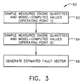
- Figure 3 is a flow chart 60 illustrating process steps executed by processor 12 in generating estimated fault magnitudes.
- a large number of engines with random variations in engine quality, deterioration, sensor bias levels, and operating conditions such as altitude, mach number, day temperature, and bleed level are simulated.
- a set of sensor readings and optional model values is obtained.
- the simulation is repeated for several faults of random magnitude within pre-defined magnitude limits.
- the same set (of course, with different values) of sensor readings and model values is again obtained.
- Data from faulted and unfaulted simulated engines are used to design processor 12, using techniques such as neural networks or linear regression.
- Y is an m by (r+1) matrix that includes the r faults, with the unfaulted case being appended as a special fault type with a constant magnitude level.
- processor 12 samples 62 measured engine quantities 14 and model values 16 at a first pre-selected operating point. At a later point in time, processor 12 samples 64 measured engine quantities 18 and model values 20, at a second pre-selected operating point. Using the measured and computed values, processor 12 then generates 66 an estimated fault vector y.
- Processor 12 generates estimates, y of the type and severity of faults that may have occurred in the engine after inputs 14 and 16 are obtained and before inputs 18 and 20 are obtained. Processor 12 generates a separate value for each type of fault under consideration, and the magnitude of a given value indicates the severity of the corresponding fault.
- an operating condition as described can include a set of operating conditions or operating points.
- a first set of operating conditions may comprise a ground idle and a takeoff point
- a second set of operating conditions may comprise a cruise point and a descent point later in the same flight.
Landscapes
- Physics & Mathematics (AREA)
- General Physics & Mathematics (AREA)
- Testing Of Engines (AREA)
- Control Of Turbines (AREA)
- Combined Controls Of Internal Combustion Engines (AREA)
Applications Claiming Priority (2)
| Application Number | Priority Date | Filing Date | Title |
|---|---|---|---|
| US466153 | 1990-01-17 | ||
| US09/466,153 US6502085B1 (en) | 1999-12-18 | 1999-12-18 | Methods and systems for estimating engine faults |
Publications (2)
| Publication Number | Publication Date |
|---|---|
| EP1114991A2 true EP1114991A2 (fr) | 2001-07-11 |
| EP1114991A3 EP1114991A3 (fr) | 2003-09-03 |
Family
ID=23850715
Family Applications (1)
| Application Number | Title | Priority Date | Filing Date |
|---|---|---|---|
| EP00311261A Withdrawn EP1114991A3 (fr) | 1999-12-18 | 2000-12-15 | Procédés et systèmes d'évaluation de défauts d'une machine |
Country Status (4)
| Country | Link |
|---|---|
| US (1) | US6502085B1 (fr) |
| EP (1) | EP1114991A3 (fr) |
| JP (1) | JP2001193477A (fr) |
| IL (1) | IL140101A (fr) |
Cited By (11)
| Publication number | Priority date | Publication date | Assignee | Title |
|---|---|---|---|---|
| EP1103926A2 (fr) * | 1999-11-26 | 2001-05-30 | General Electric Company | Procédés et dispositifs de diagnostiques à base de modèles |
| US6466858B1 (en) | 2000-11-02 | 2002-10-15 | General Electric Company | Methods and apparatus for monitoring gas turbine engine operation |
| EP1416348A1 (fr) * | 2002-10-31 | 2004-05-06 | United Technologies Corporation | Procédé d'isolation et d'identification de fautes temporelles |
| EP1418481A1 (fr) * | 2002-10-31 | 2004-05-12 | United Technologies Corporation | Procédé de diagnostique pour la performance d'une turbine à gaz |
| EP1288644A3 (fr) * | 2001-08-31 | 2006-01-11 | General Electric Company | Procédé et système de diagnose de moteurs à turbines |
| US7280941B2 (en) | 2004-12-29 | 2007-10-09 | General Electric Company | Method and apparatus for in-situ detection and isolation of aircraft engine faults |
| WO2007115140A3 (fr) * | 2006-03-31 | 2008-02-14 | Alaka I Technologies | Systèmes et procédés de surveillance de la performance des moteurs d'aeronefs |
| GB2462826A (en) * | 2008-08-20 | 2010-02-24 | Rolls Royce Plc | A method for detecting overpressure inside a compartment associated with a gas turbine nacelle |
| CN1837767B (zh) * | 2005-03-24 | 2010-05-12 | Abb研究有限公司 | 降级系统的健康参数或症状的估计 |
| CN102288412A (zh) * | 2011-05-04 | 2011-12-21 | 哈尔滨工业大学 | 基于损伤基线的航空发动机硬件损伤分析与寿命预测方法 |
| US8862433B2 (en) | 2010-05-18 | 2014-10-14 | United Technologies Corporation | Partitioning of turbomachine faults |
Families Citing this family (24)
| Publication number | Priority date | Publication date | Assignee | Title |
|---|---|---|---|---|
| US6917839B2 (en) * | 2000-06-09 | 2005-07-12 | Intellectual Assets Llc | Surveillance system and method having an operating mode partitioned fault classification model |
| US6892127B2 (en) * | 2003-02-28 | 2005-05-10 | General Electric Company | Methods and apparatus for assessing gas turbine engine damage |
| US7177785B2 (en) * | 2003-08-22 | 2007-02-13 | Honeywell International, Inc. | Systems and methods for improved aircraft performance predictions |
| US7693643B2 (en) * | 2005-02-14 | 2010-04-06 | Honeywell International Inc. | Fault detection system and method for turbine engine fuel systems |
| US7577549B2 (en) * | 2005-07-18 | 2009-08-18 | General Electric Company | System and method for trending exhaust gas temperature in a turbine engine |
| US20070260424A1 (en) * | 2006-05-05 | 2007-11-08 | Harold Brown | Methods and apparatus for estimating engine thrust |
| US7860635B2 (en) * | 2006-05-12 | 2010-12-28 | The United States Of America As Represented By The Secretary Of The Army | Singular value decomposition-based method for optimal estimation of turbofan engine thrust and other unmeasurable parameters |
| US8478473B2 (en) * | 2008-07-28 | 2013-07-02 | General Electric Company | Method and systems for controlling gas turbine engine temperature |
| RU2481564C1 (ru) * | 2011-12-29 | 2013-05-10 | Открытое акционерное общество "Научно-производственное объединение "Сатурн" (ОАО "НПО "Сатурн") | Турбореактивный двигатель, способ испытания турбореактивного двигателя, способ производства партии турбореактивных двигателей (варианты), способ эксплуатации турбореактивного двигателя |
| RU2484441C1 (ru) * | 2012-04-12 | 2013-06-10 | Открытое акционерное общество "Научно-производственное объединение "Сатурн" (ОАО "НПО "Сатурн") | Газотурбинный двигатель. способ испытания газотурбинного двигателя. способ производства партии газотурбинных двигателей (варианты). способ эксплуатации газотурбинного двигателя |
| GB2513132B (en) * | 2013-04-16 | 2015-05-27 | Ge Aviat Systems Ltd | Method for predicting a bleed air system fault |
| GB2513133B (en) | 2013-04-16 | 2015-07-08 | Ge Aviat Systems Ltd | Methods for predicting a speed brake system fault |
| GB2514108B (en) | 2013-05-13 | 2015-06-24 | Ge Aviat Systems Ltd | Method for diagnosing a bleed air system fault |
| RU2544419C1 (ru) * | 2013-11-07 | 2015-03-20 | Открытое Акционерное Общество "Уфимское Моторостроительное Производственное Объединение" (Оао "Умпо") | Способ доводки опытного газотурбинного двигателя |
| RU2551247C1 (ru) * | 2013-11-07 | 2015-05-20 | Открытое Акционерное Общество "Уфимское Моторостроительное Производственное Объединение" (Оао "Умпо") | Турбореактивный двигатель |
| RU2544638C1 (ru) * | 2013-11-07 | 2015-03-20 | Открытое Акционерное Общество "Уфимское Моторостроительное Производственное Объединение" (Оао "Умпо") | Газотурбинный двигатель |
| RU2551911C1 (ru) * | 2013-11-07 | 2015-06-10 | Открытое Акционерное Общество "Уфимское Моторостроительное Производственное Объединение" (Оао "Умпо") | Турбореактивный двигатель |
| RU2551915C1 (ru) * | 2013-11-07 | 2015-06-10 | Открытое Акционерное Общество "Уфимское Моторостроительное Производственное Объединение" (Оао "Умпо") | Способ серийного производства газотурбинного двигателя и газотурбинный двигатель, выполненный этим способом |
| RU2544409C1 (ru) * | 2013-11-07 | 2015-03-20 | Открытое Акционерное Общество "Уфимское Моторостроительное Производственное Объединение" (Оао "Умпо") | Способ серийного производства турбореактивного двигателя и турбореактивный двигатель, выполненный этим способом |
| RU2544639C1 (ru) * | 2013-11-07 | 2015-03-20 | Открытое Акционерное Общество "Уфимское Моторостроительное Производственное Объединение" (Оао "Умпо") | Способ серийного производства турбореактивного двигателя и турбореактивный двигатель, выполненный этим способом |
| DE102016008987B4 (de) * | 2015-07-31 | 2021-09-16 | Fanuc Corporation | Maschinenlernverfahren und Maschinenlernvorrichtung zum Lernen von Fehlerbedingungen, und Fehlervorhersagevorrichtung und Fehlervorhersagesystem, das die Maschinenlernvorrichtung einschließt |
| RU2640972C1 (ru) * | 2017-03-14 | 2018-01-12 | Публичное акционерное общество "ОДК - Уфимское моторостроительное производственное объединение" (ПАО "ОДК-УМПО") | Способ диагностики технического состояния двухконтурного газотурбинного двигателя при эксплуатации |
| US20230037115A1 (en) * | 2020-01-02 | 2023-02-02 | Lufthansa Technik Ag | Method and computer program product for monitoring a bleed air supply system of an aircraft |
| US11829229B2 (en) | 2022-04-26 | 2023-11-28 | Hamilton Sundstrand Corporation | Apparatus and method for diagnosing no fault failure found in electronic systems |
Citations (3)
| Publication number | Priority date | Publication date | Assignee | Title |
|---|---|---|---|---|
| US4215412A (en) * | 1978-07-13 | 1980-07-29 | The Boeing Company | Real time performance monitoring of gas turbine engines |
| WO1990009644A1 (fr) * | 1989-02-07 | 1990-08-23 | Smiths Industries Public Limited Company | Controle de fonctionnement |
| EP1103926A2 (fr) * | 1999-11-26 | 2001-05-30 | General Electric Company | Procédés et dispositifs de diagnostiques à base de modèles |
Family Cites Families (10)
| Publication number | Priority date | Publication date | Assignee | Title |
|---|---|---|---|---|
| US5402521A (en) * | 1990-02-28 | 1995-03-28 | Chiyoda Corporation | Method for recognition of abnormal conditions using neural networks |
| US5080496A (en) | 1990-06-25 | 1992-01-14 | General Electric Company | Method and apparatus for compensated temperature prediction |
| JP3196390B2 (ja) | 1992-12-25 | 2001-08-06 | 富士電機株式会社 | パラメータ同定器 |
| US5726891A (en) | 1994-01-26 | 1998-03-10 | Sisson; Patterson B. | Surge detection system using engine signature |
| US5689066A (en) | 1995-08-15 | 1997-11-18 | Stevenson; Dennis B. | Method and apparatus for analyzing gas turbine pneumatic fuel system |
| FR2739145B1 (fr) * | 1995-09-25 | 1998-12-18 | Bosch Gmbh Robert | Procede de detection des rates de combustion d'un moteur a combustion interne |
| US5751609A (en) * | 1996-10-24 | 1998-05-12 | The United States Of America As Represented By The Secretary Of The Navy | Neural network based method for estimating helicopter low airspeed |
| GB2321720A (en) | 1997-02-04 | 1998-08-05 | Secr Defence | Modelling a system with more parameters than sensors |
| US5971319A (en) * | 1997-09-05 | 1999-10-26 | Zero-Gravity Corporation | System for converting jet aircraft to parabolic flight operation |
| US6285947B1 (en) * | 1999-10-28 | 2001-09-04 | Brunswick Corporation | Prognostication of future failure of an engine indicator parameter |
-
1999
- 1999-12-18 US US09/466,153 patent/US6502085B1/en not_active Expired - Fee Related
-
2000
- 2000-12-05 IL IL14010100A patent/IL140101A/en not_active IP Right Cessation
- 2000-12-15 JP JP2000381165A patent/JP2001193477A/ja not_active Withdrawn
- 2000-12-15 EP EP00311261A patent/EP1114991A3/fr not_active Withdrawn
Patent Citations (3)
| Publication number | Priority date | Publication date | Assignee | Title |
|---|---|---|---|---|
| US4215412A (en) * | 1978-07-13 | 1980-07-29 | The Boeing Company | Real time performance monitoring of gas turbine engines |
| WO1990009644A1 (fr) * | 1989-02-07 | 1990-08-23 | Smiths Industries Public Limited Company | Controle de fonctionnement |
| EP1103926A2 (fr) * | 1999-11-26 | 2001-05-30 | General Electric Company | Procédés et dispositifs de diagnostiques à base de modèles |
Cited By (18)
| Publication number | Priority date | Publication date | Assignee | Title |
|---|---|---|---|---|
| EP1103926A2 (fr) * | 1999-11-26 | 2001-05-30 | General Electric Company | Procédés et dispositifs de diagnostiques à base de modèles |
| EP1103926A3 (fr) * | 1999-11-26 | 2003-10-01 | General Electric Company | Procédés et dispositifs de diagnostiques à base de modèles |
| US6466858B1 (en) | 2000-11-02 | 2002-10-15 | General Electric Company | Methods and apparatus for monitoring gas turbine engine operation |
| EP1288644A3 (fr) * | 2001-08-31 | 2006-01-11 | General Electric Company | Procédé et système de diagnose de moteurs à turbines |
| EP1416348A1 (fr) * | 2002-10-31 | 2004-05-06 | United Technologies Corporation | Procédé d'isolation et d'identification de fautes temporelles |
| EP1418481A1 (fr) * | 2002-10-31 | 2004-05-12 | United Technologies Corporation | Procédé de diagnostique pour la performance d'une turbine à gaz |
| US6909960B2 (en) | 2002-10-31 | 2005-06-21 | United Technologies Corporation | Method for performing gas turbine performance diagnostics |
| US7233884B2 (en) | 2002-10-31 | 2007-06-19 | United Technologies Corporation | Methodology for temporal fault event isolation and identification |
| US7280941B2 (en) | 2004-12-29 | 2007-10-09 | General Electric Company | Method and apparatus for in-situ detection and isolation of aircraft engine faults |
| CN1837767B (zh) * | 2005-03-24 | 2010-05-12 | Abb研究有限公司 | 降级系统的健康参数或症状的估计 |
| WO2007115140A3 (fr) * | 2006-03-31 | 2008-02-14 | Alaka I Technologies | Systèmes et procédés de surveillance de la performance des moteurs d'aeronefs |
| US7979192B2 (en) | 2006-03-31 | 2011-07-12 | Morrison Brian D | Aircraft-engine trend monitoring system |
| GB2462826A (en) * | 2008-08-20 | 2010-02-24 | Rolls Royce Plc | A method for detecting overpressure inside a compartment associated with a gas turbine nacelle |
| US7930928B2 (en) | 2008-08-20 | 2011-04-26 | Rolls-Royce Plc | Method for detecting overpressure inside a compartment associated with a gas turbine nacelle |
| GB2462826B (en) * | 2008-08-20 | 2014-03-12 | Rolls Royce Plc | A method for detecting overpressure inside a compartment associated with a gas turbine nacelle |
| US8862433B2 (en) | 2010-05-18 | 2014-10-14 | United Technologies Corporation | Partitioning of turbomachine faults |
| CN102288412A (zh) * | 2011-05-04 | 2011-12-21 | 哈尔滨工业大学 | 基于损伤基线的航空发动机硬件损伤分析与寿命预测方法 |
| CN102288412B (zh) * | 2011-05-04 | 2013-05-01 | 哈尔滨工业大学 | 基于损伤基线的航空发动机硬件损伤分析与寿命预测方法 |
Also Published As
| Publication number | Publication date |
|---|---|
| IL140101A (en) | 2004-06-01 |
| US6502085B1 (en) | 2002-12-31 |
| JP2001193477A (ja) | 2001-07-17 |
| IL140101A0 (en) | 2002-02-10 |
| EP1114991A3 (fr) | 2003-09-03 |
Similar Documents
| Publication | Publication Date | Title |
|---|---|---|
| US6502085B1 (en) | Methods and systems for estimating engine faults | |
| EP1103926B1 (fr) | Procédés et dispositifs de diagnostiques à base de modèles | |
| EP1790838B1 (fr) | Estimation de la qualité des composants d'une turbine à gaz basé sur un modèle | |
| US6466858B1 (en) | Methods and apparatus for monitoring gas turbine engine operation | |
| Barad et al. | Neural network approach for a combined performance and mechanical health monitoring of a gas turbine engine | |
| EP2149824B1 (fr) | Procédés et systèmes pour évaluer les paramètres de fonctionnement d'un moteur | |
| Panov | Auto-tuning of real-time dynamic gas turbine models | |
| Li et al. | Study on gas turbine gas-path fault diagnosis method based on quadratic entropy feature extraction | |
| Yang et al. | A strong tracking filter based multiple model approach for gas turbine fault diagnosis | |
| Yildirim et al. | Engine health monitoring in an aircraft by using Levenberg-Marquardt feedforward neural network and radial basis function network | |
| Verbist et al. | Experience with gas path analysis for on-wing turbofan condition monitoring | |
| Baig et al. | Model-based reasoning for fault diagnosis of twin-spool turbofans | |
| Gorinevsky et al. | Model-based diagnostics for small-scale turbomachines | |
| Kim et al. | Suitability of performance adaptation methods for updating the thermodynamic cycle model of a turboprop engine | |
| Rausch et al. | Integrated in-flight fault detection and accommodation: a model-based study | |
| Biraud et al. | Simulation of the WR-21 Advanced Cycle Engine | |
| Borguet et al. | Assessment of an anomaly detector for jet engine health monitoring | |
| Sankar et al. | Design point parameter estimation of a legacy twin spool turbojet engine for health monitoring | |
| Romessis et al. | Implementation of stochastic methods for industrial gas turbine fault diagnosis | |
| Borguet et al. | A way to deal with model-plant mismatch for a reliable diagnosis in transient operation | |
| Witoś et al. | Expert SHM and CM of Turbojet Engine FCU Using Instantaneous Angular Speed Signal | |
| Menga et al. | Extreme Learning Machine-Based Diagnostics for Component Degradation in a Microturbine. Energies 2022, 15, 7304 | |
| Pisano et al. | The CEDAR project-commercial engine damage assessment and reconfiguration | |
| Roig Tió et al. | Considerations on Axial Compressor Bleed for Sub-Idle Performance Models | |
| Hill | Reduced order modelling of gas turbine engines |
Legal Events
| Date | Code | Title | Description |
|---|---|---|---|
| PUAI | Public reference made under article 153(3) epc to a published international application that has entered the european phase |
Free format text: ORIGINAL CODE: 0009012 |
|
| AK | Designated contracting states |
Kind code of ref document: A2 Designated state(s): AT BE CH CY DE DK ES FI FR GB GR IE IT LI LU MC NL PT SE TR |
|
| AX | Request for extension of the european patent |
Free format text: AL;LT;LV;MK;RO;SI |
|
| PUAL | Search report despatched |
Free format text: ORIGINAL CODE: 0009013 |
|
| AK | Designated contracting states |
Kind code of ref document: A3 Designated state(s): AT BE CH CY DE DK ES FI FR GB GR IE IT LI LU MC NL PT SE TR |
|
| AX | Request for extension of the european patent |
Extension state: AL LT LV MK RO SI |
|
| RIC1 | Information provided on ipc code assigned before grant |
Ipc: 7F 01D 21/00 B Ipc: 7G 07C 3/00 B Ipc: 7G 01M 15/00 A |
|
| 17P | Request for examination filed |
Effective date: 20040303 |
|
| AKX | Designation fees paid |
Designated state(s): AT BE CH CY DE DK ES FI FR GB GR IE IT LI LU MC NL PT SE TR |
|
| GRAP | Despatch of communication of intention to grant a patent |
Free format text: ORIGINAL CODE: EPIDOSNIGR1 |
|
| STAA | Information on the status of an ep patent application or granted ep patent |
Free format text: STATUS: THE APPLICATION IS DEEMED TO BE WITHDRAWN |
|
| 18D | Application deemed to be withdrawn |
Effective date: 20071211 |