EP1114949A2 - Epicyclic gear train - Google Patents
Epicyclic gear train Download PDFInfo
- Publication number
- EP1114949A2 EP1114949A2 EP00309600A EP00309600A EP1114949A2 EP 1114949 A2 EP1114949 A2 EP 1114949A2 EP 00309600 A EP00309600 A EP 00309600A EP 00309600 A EP00309600 A EP 00309600A EP 1114949 A2 EP1114949 A2 EP 1114949A2
- Authority
- EP
- European Patent Office
- Prior art keywords
- star
- lubricant
- gear
- mesh
- sun
- Prior art date
- Legal status (The legal status is an assumption and is not a legal conclusion. Google has not performed a legal analysis and makes no representation as to the accuracy of the status listed.)
- Granted
Links
Images


Classifications
-
- F—MECHANICAL ENGINEERING; LIGHTING; HEATING; WEAPONS; BLASTING
- F16—ENGINEERING ELEMENTS AND UNITS; GENERAL MEASURES FOR PRODUCING AND MAINTAINING EFFECTIVE FUNCTIONING OF MACHINES OR INSTALLATIONS; THERMAL INSULATION IN GENERAL
- F16H—GEARING
- F16H1/00—Toothed gearings for conveying rotary motion
- F16H1/28—Toothed gearings for conveying rotary motion with gears having orbital motion
- F16H1/2809—Toothed gearings for conveying rotary motion with gears having orbital motion with means for equalising the distribution of load on the planet-wheels
- F16H1/2827—Toothed gearings for conveying rotary motion with gears having orbital motion with means for equalising the distribution of load on the planet-wheels by allowing limited movement of the planet carrier, e.g. relative to its shaft
-
- F—MECHANICAL ENGINEERING; LIGHTING; HEATING; WEAPONS; BLASTING
- F16—ENGINEERING ELEMENTS AND UNITS; GENERAL MEASURES FOR PRODUCING AND MAINTAINING EFFECTIVE FUNCTIONING OF MACHINES OR INSTALLATIONS; THERMAL INSULATION IN GENERAL
- F16H—GEARING
- F16H57/00—General details of gearing
- F16H57/04—Features relating to lubrication or cooling or heating
- F16H57/048—Type of gearings to be lubricated, cooled or heated
- F16H57/0482—Gearings with gears having orbital motion
-
- F—MECHANICAL ENGINEERING; LIGHTING; HEATING; WEAPONS; BLASTING
- F05—INDEXING SCHEMES RELATING TO ENGINES OR PUMPS IN VARIOUS SUBCLASSES OF CLASSES F01-F04
- F05D—INDEXING SCHEME FOR ASPECTS RELATING TO NON-POSITIVE-DISPLACEMENT MACHINES OR ENGINES, GAS-TURBINES OR JET-PROPULSION PLANTS
- F05D2260/00—Function
- F05D2260/98—Lubrication
-
- F—MECHANICAL ENGINEERING; LIGHTING; HEATING; WEAPONS; BLASTING
- F16—ENGINEERING ELEMENTS AND UNITS; GENERAL MEASURES FOR PRODUCING AND MAINTAINING EFFECTIVE FUNCTIONING OF MACHINES OR INSTALLATIONS; THERMAL INSULATION IN GENERAL
- F16H—GEARING
- F16H1/00—Toothed gearings for conveying rotary motion
- F16H1/28—Toothed gearings for conveying rotary motion with gears having orbital motion
- F16H2001/289—Toothed gearings for conveying rotary motion with gears having orbital motion comprising two or more coaxial and identical sets of orbital gears, e.g. for distributing torque between the coaxial sets
-
- F—MECHANICAL ENGINEERING; LIGHTING; HEATING; WEAPONS; BLASTING
- F16—ENGINEERING ELEMENTS AND UNITS; GENERAL MEASURES FOR PRODUCING AND MAINTAINING EFFECTIVE FUNCTIONING OF MACHINES OR INSTALLATIONS; THERMAL INSULATION IN GENERAL
- F16H—GEARING
- F16H57/00—General details of gearing
- F16H57/04—Features relating to lubrication or cooling or heating
- F16H57/0456—Lubrication by injection; Injection nozzles or tubes therefor
-
- Y—GENERAL TAGGING OF NEW TECHNOLOGICAL DEVELOPMENTS; GENERAL TAGGING OF CROSS-SECTIONAL TECHNOLOGIES SPANNING OVER SEVERAL SECTIONS OF THE IPC; TECHNICAL SUBJECTS COVERED BY FORMER USPC CROSS-REFERENCE ART COLLECTIONS [XRACs] AND DIGESTS
- Y10—TECHNICAL SUBJECTS COVERED BY FORMER USPC
- Y10T—TECHNICAL SUBJECTS COVERED BY FORMER US CLASSIFICATION
- Y10T74/00—Machine element or mechanism
- Y10T74/19—Gearing
- Y10T74/19991—Lubrication
- Y10T74/19995—Teeth
Abstract
Description
- The present invention relates to epicyclic gear trains and particularly to an epicyclic gear train configured as a star gear system and having effective, simple means for supplying lubricant to selected components of the gear system and for recovering used lubricant.
- Epicyclic gear trains are used to reduce rotational speeds in various types of machinery. Depending on the speed reduction ratio desired, an epicyclic gear train can be configured as either a planetary system or a star system. A planetary system includes a central sun gear and a set of planet gears rotatably mounted on a gear carrier by bearings. The planet gears are circumferentially distributed about the periphery of the sun gear so that the planet gears mesh with the sun gear. A mechanically grounded, internally toothed ring gear circumscribes and meshes with the planet gears. Input and output shafts extend from the sun gear and gear carrier respectively. In operation, the input shaft rotatably drives the sun gear, compelling each planet gear to rotate about its own axis and, because the ring gear is mechanically grounded, causing the planet gears to orbit the sun gear. The planet gear orbital motion turns the carrier, and hence the output shaft, in the same direction as the input shaft.
- A star system is similar to the above described planetary system except that the gear carrier is mechanically grounded, the ring gear is rotatable and the output shaft extends from the ring gear. Because the carrier is grounded, the "planet" gears cannot orbit the sun and therefore are referred to as star gears. In operation, the input shaft rotatably drives the sun gear, compelling each star gear to rotate about its own axis. The rotary motion of the star gears turns the ring gear, and hence the output shaft, in a direction opposite that of the input shaft.
- An epicyclic gear train, whether configured as a planetary system or a star system, also has a lubrication system to lubricate and cool the gear teeth and bearings and to remove used lubricant so that it can be reconditioned (cooled, filtered, de-aerated) and reused. It is desirable to remove the used lubricant as completely and quickly as possible, otherwise the gears continually agitate the residual lubricant. Agitation of the residual lubricant degrades the power transmission efficiency of the gear system and elevates the lubricant temperature, making it more difficult to cool the lubricant to render it suitable for repeated use as a heat transfer medium. If the gear train is a component of an aircraft engine, degraded efficiency is unacceptable because it reduces aircraft range and/or payload. The problem of elevated lubricant temperature can be addressed with larger, higher capacity heat exchangers. However larger heat exchangers are unacceptable because they contribute undesirable weight and consume precious space on board the engine or aircraft.
- US Patent 5,472,383 discloses a lubricant supply and recovery system for a planetary gear system. Noteworthy features of the system include a set of
lubricant spray bars 32 intermediate each pair ofplanet gears 10, a set of interplanet baffles 80 each having atrough 82, and a set ofcollection channels 56. In operation, thespray bars 32direct lubricant jets planet gears 8, 10. Most of thelubricant 34 passes through the sun/planet mesh. Much of the lubricant that passes through the sun/planet mesh is urged axially outwardly by the gear mesh and directly enters thecollection channels 56. The balance of the lubricant that passes through the sun/planet mesh, along with lubricant reflected from the sun gear, is centrifuged into thenearby baffle trough 82, urged through outlets 84 in the planet carrier and finally deposited in thenonrotating collection channels 56. Meanwhile, theplanet gears 10 carrylubricant 36 radially outwardly and into the planet/ring mesh. Lubricant expelled from the planet/ring mesh then enters thecollection channels 56. Concurrently, pressurized lubricant enters the narrow bearing annulus (unnumbered) defined by theouter surface 44 of each journal bearing 16 and theinner surface 46 of thecorresponding planet gear 10. Lubricant discharged from the bearing annuli enters thecollection channels 56. Lubricant collected by thechannels 56 enters adrain line 62, which conveys the lubricant to the lubrication system coolers, filters and de-aerators. - Despite the merits of the above described planetary lubrication system, it suffers from at least five shortcomings when applied to a star system. First, it relies on the centrifugal forces arising from carrier rotation to evacuate used lubricant. These forces are absent in the star system because the gear carrier is mechanically grounded. Second, the disclosed planetary system suffers from the complexity of two lubricant circuits, one to serve the planet gear journal bearings and one to serve the gear meshes. Both circuits are necessary. The gear lubrication circuit is necessary because the bearing lubricant, upon exiting the bearing annuli, is centrifuged away from the sun/planet mesh and so is unavailable to lubricate that mesh. The bearing lubrication circuit is necessary because the gear lubricant, after having been discharged from the spray bars, cannot be locally repressurized and introduced into the bearing annuli. Although the two circuits may share certain components (e.g. coolers, pumps, filters and de-aerators) other components (e.g. supply lines, spray bars) are unshared and introduce unwelcome complexity. Third, the presence of the dual lubricant circuits dictates that sufficient lubricant be available to concurrently supply both circuits, a distinct disadvantage in aircraft applications where space is at a premium and excess weight is always undesirable. Fourth, because the bearing lubricant cannot serve the gear meshes and vice versa, lubricant must be supplied in parallel to both the bearings and the gear meshes. As a result, a greater quantity of lubricant enters the gear system than would be the case if the bearings and gears were lubricated in series. The excess lubricant can exceed the lubricant evacuation capacity of the gear system thereby increasing lubricant residence time. The increased residence time provides additional opportunity for lubricant agitation and the concomitant loss of transmission efficiency and increased lubricant temperature described above. Fifth, the bearing lubricant and gear lubricant typically originate from a common source. This makes it impractical to customize the lubricant temperature to optimally satisfy the requirements of both the bearing annulus, which requires relatively cool lubricant, and the gear meshes, which benefit from warmer lubricant.
- What is needed is a simple lubrication system for supplying lubricant to both the star gear bearings and the gear meshes in a star configured epicyclic gear train and for quickly and effectively evacuating used lubricant.
- According to one aspect of the invention, a star configured epicyclic gear train includes a set of inter-star baffles for constraining the flow of lubricant and a lubricant circuit that serves as the exclusive means for successively lubricating the star gear bearings, the sun/star gear mesh and the star/ring gear mesh. According to a second aspect of the invention, a star configured epicyclic gear train includes inter-star baffles and two lubricant circuits, a primary circuit and an auxiliary circuit, that share a common lubricant discharge path. Ideally, the auxiliary circuit is selectively operable. The invention also embraces methods for lubricating a star configured epicyclic gear train and for effectively evacuating used lubricant.
- One significant advantage of the invention is that it promotes evacuation of used lubricant from a star gear system despite the absence of gear carrier rotation and the accompanying centrifugal forces.
- A second significant advantage of the invention, particularly the single circuit variant, is its simplicity.
- A third advantage of the invention is that it conserves space and reduces weight by minimizing the quantity of lubricant that must be carried on board an aircraft when the inventive gear system is used as a component of an aircraft engine
- A fourth advantage of the invention is that it minimizes the quantity of lubricant requiring evacuation from the gear system and therefore helps to boost efficiency and attenuate undesirable lubricant temperature rise.
- A fifth advantage is that the lubricant temperature gradually rises as the lubricant proceeds through the gear system. The temperature rise conforms to the lubricant temperature requirements and temperature tolerances of the gear system components.
- Some preferred embodiments of the present invention will now be described, by way of example only, with reference to the accompanying drawings in which:
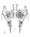
- Figure 1 is a cross sectional side elevation view of a first star gear system in accordance with the invention with a single lubricant circuit.
- Figure 2 is a view taken in the
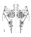
direction 2--2 of Figure 1. - Figure 3 is a cross sectional side elevation view of a second star gear system in accordance with the invention with primary and auxiliary lubricant circuits.
- Figure 4 is a view taken in the
direction 4--4 of Figure 3. - Figure 5 is a view of the gear train of either Figures 1 or 3 enlarged to illustrate certain details of a lubricant discharge path.
-
- Referring to Figures 1, 2 and 5, a star gear system for reducing shaft speed in an aircraft engine includes a
sun gear 10 rotatable about anaxis 11. The sun gear is driven by aninput shaft 12 coupled to the sun gear by aspline connection 13. The input shaft includesflexible elements 14 to minimize misalignment between the intermeshing teeth of the sun gear and a set of star gears. Theflexible elements 14 are substantially as described in US Patent 5,433,674, to which further reference may be made for further detail. - The gear system includes a plurality of star gears 16 and a nonrotatable
star gear carrier 17. Each star gear is rotatably mounted on the carrier by a journal bearing 18 so that the star gears surround the sun gear and are each engaged with the sun gear to define a sun/star mesh 19. Thebearing 18 is preferably a load equalizing bearing as described in US Patent 5,102,379, to which further reference may be made for further detail. - A narrow annulus bordered by the radially
outer surface 21 of each bearing 18 and the radially inner surface of eachstar gear 16 defines aninterface 23 between each bearing and its respective star gear. The radially inner surface of each star gear is coated as described in US Patent 5,685,797, to which further reference may be made for further detail. Axially and radially extendinglubricant conduits conduits 26 communicate with a shallow,local recess 27 formed in the outer surface of each bearing. Eachconduit 24 communicates with anannular lubricant distributor 28 by way offittings 29. Asupply tube 31 connects the distributor to a source of lubricant, not shown. - The
gear carrier 17 includes forward andaft side plates openings carrier 17 is unpenetrated by openings dedicated to removal of lubricant from the gear train. The carrier is mechanically grounded to anengine case 36 by atorque frame 37 and aflexible coupling 38. Thetorque frame 37 has a set of axially extendingfingers 39 that project through theopenings 35 in the aft side plate. A spherical bearing 41 couples each finger to the torque frame. The radially outer end of the torque frame is connected to the forward end of the flexible coupling by a set offasteners 42. The aft end of the coupling is connected to the engine case by another set offasteners 43. to mechanically ground the carrier. The torque frame is substantially as described in US Patent 5,466,198 with the exception that the present torque frame conveys torque reactions from thecarrier 17 to the case 36 (by way of the flexible coupling 38) whereas the referenced torque frame conveys torque and rotary motion from the carrier of a planetary gear system to the gear system output shaft. The contents of US Patent 5,466,198 may be referred to for further details of this arrangement. Theflexible coupling 38 is substantially as described in US Patent 5,433,674 with the exception that the present coupling conveys torque reactions from thenonrotatable gear carrier 17 to thecase 36 whereas the corresponding coupling of the reference patent conveys torque reactions from a nonrotatable ring gear to an engine case. - As seen best in Fig. 2, the gear carrier also includes a set of baffles, generically designated 44 and individually designated with letters A, B, C, D and E. Each baffle is disposed between two of the star gears. Each baffle has an
ascendent flank 46 adjacent the ascending (radially outwardly progressing) side of one of the adjacent star gears and adescendent flank 47 adjacent the descending (radially inwardly progressing) side of the other of the adjacent star gears. The baffle flanks 46, 47 are each arcuately contoured so that the clearance between each flank and the adjacent gear teeth is as small as reasonably possible. Thedescendent flank 47 of each baffle is foreshortened to define a roughly triangular, axially extendingspace 48 bordered by the baffle and by sectors of the sun gear and adjacent star gear. It is theorized that thespace 48 may facilitate distribution of lubricant in the axial direction. Adepression 49 in each baffle extends axially between the forward and aft side plates of the gear carrier. Each depression is substantially parallel toaxis 11, i.e. the radial distance between theaxis 11 and a representative depression is constant along the entire axial length of the depression. Unlike the visually similar baffle troughs seen in US Patent 5,472,383, the depressions do not serve as a means for evacuating lubricant from the gear system because the carrier, being mechanically grounded, fails to centrifuge lubricant into the depressions. Any lubricant that splashes into the three upper troughs, A, B and E, will immediately drain out. Lubricant may accumulate in the lower troughs C and D. However, since the carrier side plates are not penetrated by openings at the axial extremities of the depressions or by other openings dedicated to the removal of lubricant, accumulated lubricant will remain puddled in troughs C and D. - A rotatable,
ring gear 51 comprises forward and aftring gear sections internal gear teeth 52 andexternal spline teeth 53. Thering gear 51 circumscribes the star gears and engages each star gear to define a star/ring mesh 54. Circumferentially distributedlubricant discharge ports 56 penetrate radially through the ring gear. - As seen most clearly in Figure 5, a ring
gear housing assembly 57 includes forward andaft housing sections splash shield 62 extending axially from each flange, and agear retainer 63 perforated by circumferentially distributedapertures 64. The housing assembly also includes anantirotation ring 65. The antirotation ring comprises asupport ring 66 and anintegral spline ring 67 having spline teeth 68.Bolts 71 trap thesupport ring 66 between the bolting flanges 61 so that thespline teeth 53, 68 couple the housing assembly to the ring gear ensuring that the housing assembly corotates with the ring gear. A series of circumferentially distributedlubricant discharge slots 69 extend axially between thehousing sections spline ring 67 and radially between thesupport ring 66 and the flanges 61. Theslots 69 are distributed circumferentially intermediate thebolts 71. Thegear retainers 63 trap the ring gear axially within the housing assembly and help to define forward and aftannular lubricant collectors 72. A nonrotatable, circumferentially extendinggutter 73 is bolted to bearingsupport 74 so that gutter sidewalls 75 are nearly in contact with thesplash shield 62. Adrain pipe 76 extends from the gutter to convey lubricant away from the gear system. - The
forward section 58 of thehousing assembly 57 includes a cylindrical extension 77 bolted to apower output shaft 78.Tapered roller bearings 79 support the aft end of the output shaft on the bearingsupport 74. - The sun, star and ring gears are bihelical gears whose teeth, if extended to gear
centerplane 81, would form a series of apexes. Depending on the rotational sense of the gears, each apex either leads or trails its constuituent gear teeth. Rotation with the apexes trailing is preferred because it forces lubricant in the gear mesh axially inwardly, toward thecenterplane 81 to ensure adequate lubrication across the faces of the gear teeth. Rotational arrows signify the rotational sense of the gears in Figure 2. - A lubricant circuit extends through the gear system and serves as the exclusive means for supplying lubricant successively to the bearing interfaces, the sun/star mesh and the star/ring mesh. Pressurized lubricant flows successively through the
supply tube 31, theannular lubricant distributor 28, thefittings 29, and the bearingconduits annular bearing interface 23 by way of the bearing recesses 27. Lubricant introduced into a bearing interface spreads out axially and circumferentially to form a load supporting lubricant film between the bearingouter surface 21 and the star gearinner surface 22. The lubricant is then discharged from the axial extremities of the bearing interface. Substantially all of the discharged lubricant is directed into the sun/star mesh 19, partly because of the presence of the nearbydescendent baffle flank 47 and partly because of suction created by the rapidly rotating sun and star gears in thespace 48. The directed lubricant cools and lubricates the sun and star gear teeth and then is expelled from the sun/star mesh. The nearby ascendent baffle flank then guides substantially all of the expelled lubricant radially outwardly and into the star/ring mesh 54. The lubricant is then ejected from the star/ring mesh. - The ejected lubricant is then centrifugally channeled away from the gear train. Since the action of the bihelical gear teeth tends to force lubricant axially inwardly toward the
gear centerplane 81, most of the ejected lubricant flows through thedischarge ports 56. The lubricant then flows axially along thespline teeth 53, 68, around the axial extremities of thespline ring 67 and then into thedischarge slots 69. The balance of the lubricant enters thecollectors 72, and then flows through theapertures 64 and thedischarge slots 69. Lubricant that entersslots 69 then flows into thegutter 73. Thesplash shield 62 helps to confine the lubricant in the gutter. The lubricant then flows into thedrain pipe 76, which conveys the lubricant to the lubrication system coolers, filters and deaerators. - As the lubricant proceeds through the gear system, its temperature gradually rises in concert with the lubricant temperature requirements and temperature tolerances of the bearing interface, sun/star mesh and star/ring mesh. The lubricant entering the interface is relatively cool, about 200°F (93°C). The bearing interfaces 23 require such cool lubricant to support the tremendous reaction forces that the star gears impose on the bearings. By the time the lubricant exits the interface, its temperature has increased to about 240°F (115°C), a temperature not incompatible with the sun/star mesh, which can tolerate warmer lubricant without compromising gear durability or appreciably affecting heat transfer. By the time the lubricant exits the sun/star mesh, its temperature has increased to about 280°F (138°C). The 280°F (138°C) lubricant may be suboptimally warm for the sun/star mesh. However it is at least tolerable for the star/ring mesh, which is the next component to be lubricated. The star/ring mesh has greater tolerance for warmer lubricant because there is less relative sliding between the star gear teeth and the ring gear teeth than there is between the sun gear teeth and the star gear teeth.
- Figures 3 and 4 illustrate a variant of the star configured epicyclic gear train just described. The illustrated alternative system includes a primary lubricant circuit and an auxiliary lubricant circuit. The components and operation of the primary circuit are substantially the same as the components and operation of the single lubricant circuit described above. However, in the alternative system, the annular lubricant distributor comprises a primary distributor 28a that receives lubricant from
supply tube 31a and an auxiliary distributor that receives lubricant fromauxiliary supply tube 31b. Axially extendingspray bars 82 havingspray orifices 83 are disposed between each pair of star gears. Each spray bar is connected to theauxiliary lubricant distributor 31b by a fitting 29b. The spray bars are part of the auxiliary lubricant circuit. - In operation, the primary circuit operates substantially the same as the single supply circuit described above. The auxiliary circuit introduces jets auxiliary lubricant into the gear system by way of the
spray bar orifices 83. Substantially all of the auxiliary lubricant and substantially all of the primary lubricant, concurrently enter the sun/star mesh. Once introduced into the gear system, the auxiliary lubricant comingles with the primary lubricant and follows a common lubricant discharge path. The common lubricant discharge path extends through the sun/star mesh and the star/ring mesh and is the exclusive means for evacuating both the primary lubricant and the auxiliary lubricant. The comingled lubricant is then channeled away from the gear system by way of thedischarge ports 56,collectors 72,apertures 64,discharge slots 69,gutter 73, anddrain pipe 76 as described above. - The spray bars introduce some additional complexity into the gear system. Moreover, the auxiliary lubricant supplied by the spray bars may result in the accumulation of residual lubricant, and the attendant degradation of power transmission efficiency and lubricant temperature rise described above. Nevertheless, the auxiliary lubrication system may be of value when the lubrication and cooling demands of the gear system exceed the capacity of the primary lubricant circuit. Such capacity exceedance may occur temporarily in an aircraft engine during operation at or near peak power. However, operation at peak power usually occurs only during the relatively brief takeoff and climb segments of an aircraft mission. The longer duration cruise and landing segments of the mission are flown at lower power settings where the primary lubrucation system is more than adequate and the auxiliary system is redundant. Accordingly, it is beneficial to make the auxiliary system selectively operable.
- Although the invention has been described with reference to a preferred embodiment thereof, those skilled in the art will appreciate that various changes, modifications and adaptations can be made without departing from the invention as set forth in the accompanying claims.
Claims (13)
- A rotary gear train, comprising:a rotatable sun gear (10);a nonrotatable star gear carrier (17);a plurality of circumferentially distributed star gears (16) each rotatably mounted on the carrier (17) by a bearing (18) having an interface (23) with its respective star gear (16) and each engaged with the sun gear (10) to define a sun/star mesh (19);a rotatable ring gear (51) circumscribing the star gears (16) and engaged with each star gear (16) to define a star/ring mesh (54);a set of baffles (44), each baffle disposed between two star gears (16); anda lubricant circuit serving as the exclusive means for supplying lubricant successively to the bearing interfaces (23), the sun/star mesh (19) and the star/ring mesh (54).
- The gear train of claim 1 wherein the lubricant circuit includes a lubricant collector (72) corotatable with the ring gear (51).
- The gear train of claim 2 wherein the lubricant circuit also includes a nonrotatable gutter (73) circumscribing the collector (72).
- A rotary gear train, comprising:a rotatable sun gear (10);a nonrotatable star gear carrier (17);a plurality of circumferentially distributed star gears (16) each rotatably mounted on the carrier (17) by a bearing (18) having an interface (23) with its respective star gear (16) and each engaged with the sun gear (10) to define a sun/star mesh (19);a rotatable ring gear (51) circumscribing the star gears (16) and engaged with each star gear (16) to define a star/ring mesh (54);a set of baffles (44), each baffle disposed between two star gears (16);a primary lubricant circuit for supplying primary lubricant successively to the bearing interface (23), the sun/star mesh (19) and the star/ring mesh (54); andan auxiliary lubricant circuit for supplying auxiliary lubricant to the sun/star mesh (19) and the star/ring mesh (54);wherein the primary and auxiliary lubricant circuits include a common lubricant discharge path that extends through the sun/star mesh, the common path being the exclusive means for evacuating both the primary lubricant and the auxiliary lubricant.
- The gear train of claim 4 wherein the common lubricant discharge path also extends through the star/ring mesh (54).
- The gear train of claim 4 or 5 wherein the common path includes a lubricant collector (72) corotatable with the ring gear (51).
- The gear train of claim 6 wherein the common path also includes a nonrotatable gutter (73) circumscribing the collector (72).
- The gear train of any one of claims 4 to 7 wherein the auxiliary lubricant circuit comprises a set of spray bars (82), each spray bar (82) disposed between two star gears (16) .
- The gear train of any of claims 5 to 8 wherein the auxiliary lubricant circuit is selectively operable.
- The gear train of any preceding claim wherein the carrier (17) comprises a pair of side plates (32,33) unpenetrated by openings dedicated to the removal of lubricant from the gear train.
- A rotary gear train, comprising:a rotatable sun gear (10);a nonrotatable star gear carrier (17);a plurality of circumferentially distributed star gears (16) each rotatably mounted on the carrier (17) by a bearing (18) having an interface (23) with its respective star gear (16) and each engaged with the sun gear (10) to define a sun/star mesh (19);a rotatable ring gear (51) circumscribing the star gears (16) and engaged with each star gear (16) to define a star/ring mesh (54);a set of baffles (44), each baffle disposed between two star gears (16); anda lubricant circuit for supplying lubricant successively to the bearing interfaces (23), the sun/star mesh (19) and the star/ring mesh (54).
- A method of lubricating a gear train having a sun gear (10), a plurality of star gears (16) each rotatably mounted on a carrier (17) by a bearing (18) having an interface (23) with its respective star gear (16) and each engaged with the sun gear (10) to define a sun/star mesh (19), and a ring gear (51) circumscribing the star gears (16) and engaged with each star gear (16) to define a star/ring mesh (54), the method comprising:introducing lubricant into the bearing interface (23);discharging the introduced lubricant from the interface (23);directing substantially all of the discharged lubricant into the sun/star mesh (19);expelling substantially all of the directed lubricant from the sun/star mesh (54);guiding substantially all of the expelled lubricant into the star/ring mesh (54);ejecting substantially all of the guided lubricant from the star/ring mesh (54); andchanneling the ejected lubricant away from the gear train.
- A method of lubricating a gear train having a sun gear (10), a plurality of star gears (16) each rotatably mounted on a carrier (17) by a bearing (18) having an interface (23) with the star gear (16) and each engaged with the sun gear (10) to define a sun/star mesh (19), and a ring gear (51) circumscribing the star gears (16) and engaged with each star gear (16) to define a star/ring mesh (54), the method comprising:introducing a primary lubricant into the bearing interface (23);discharging the introduced primary lubricant from the interface (23);concurrently directing substantially all of the discharged first lubricant and an auxiliary lubricant into the sun/star mesh (19);expelling substantially all of the directed primary and auxiliary lubricant from the sun/star mesh (19) ;guiding substantially all of the expelled primary and auxiliary lubricant into the star/ring mesh (54);ejecting substantially all of the guided primary and auxiliary lubricant from the star/ring mesh (54); andchanneling the ejected primary and auxiliary lubricant away from the gear train.
Applications Claiming Priority (2)
| Application Number | Priority Date | Filing Date | Title |
|---|---|---|---|
| US470230 | 1999-12-22 | ||
| US09/470,230 US6223616B1 (en) | 1999-12-22 | 1999-12-22 | Star gear system with lubrication circuit and lubrication method therefor |
Publications (3)
| Publication Number | Publication Date |
|---|---|
| EP1114949A2 true EP1114949A2 (en) | 2001-07-11 |
| EP1114949A3 EP1114949A3 (en) | 2001-08-16 |
| EP1114949B1 EP1114949B1 (en) | 2004-07-07 |
Family
ID=23866768
Family Applications (1)
| Application Number | Title | Priority Date | Filing Date |
|---|---|---|---|
| EP00309600A Expired - Lifetime EP1114949B1 (en) | 1999-12-22 | 2000-10-31 | Epicyclic gear train |
Country Status (4)
| Country | Link |
|---|---|
| US (1) | US6223616B1 (en) |
| EP (1) | EP1114949B1 (en) |
| JP (1) | JP4919533B2 (en) |
| DE (1) | DE60011988T2 (en) |
Cited By (18)
| Publication number | Priority date | Publication date | Assignee | Title |
|---|---|---|---|---|
| CN103089450A (en) * | 2011-10-27 | 2013-05-08 | 联合工艺公司 | Gas turbine engine front center body architecture |
| CN103089449A (en) * | 2011-10-27 | 2013-05-08 | 联合工艺公司 | Gas turbine engine front center body architecture |
| EP2610527A3 (en) * | 2011-12-30 | 2013-09-25 | United Technologies Corporation | Epicyclic gear train and turbine engine |
| US8708863B2 (en) | 2006-08-15 | 2014-04-29 | United Technologies Corporation | Epicyclic gear train |
| US8740740B2 (en) | 2006-08-15 | 2014-06-03 | United Technologies Corporation | Ring gear mounting arrangement with oil scavenge scheme |
| US8858388B2 (en) | 2006-08-15 | 2014-10-14 | United Technologies Corporation | Gas turbine engine gear train |
| US8894538B2 (en) | 2006-08-15 | 2014-11-25 | United Technologies Corporation | Gas turbine engine with geared architecture |
| US8911204B2 (en) | 2011-04-15 | 2014-12-16 | United Technologies Corporation | Gas turbine engine front center body architecture |
| US8915702B2 (en) | 2011-04-15 | 2014-12-23 | United Technologies Corporation | Gas turbine engine front center body architecture |
| US8939864B2 (en) | 2006-08-15 | 2015-01-27 | United Technologies Corporation | Gas turbine engine lubrication |
| EP2584153A3 (en) * | 2011-10-17 | 2015-10-14 | United Technologies Corporation | Gas turbine engine front center body architecture and method of disassembly |
| US9976437B2 (en) | 2006-08-15 | 2018-05-22 | United Technologies Corporation | Epicyclic gear train |
| US10082105B2 (en) | 2006-08-15 | 2018-09-25 | United Technologies Corporation | Gas turbine engine with geared architecture |
| US10605167B2 (en) | 2011-04-15 | 2020-03-31 | United Technologies Corporation | Gas turbine engine front center body architecture |
| EP3696448A1 (en) | 2019-02-14 | 2020-08-19 | Safran Transmission Systems | Lubrication of a planet carrier for a mechanical gear of a turbine engine, in particular for an aircraft |
| EP3696449A1 (en) | 2019-02-14 | 2020-08-19 | Safran Transmission Systems | Lubrication of a planet carrier for a mechanical gear of a turbine engine, in particular for an aircraft |
| US10914240B2 (en) | 2018-06-27 | 2021-02-09 | Rolls-Royce Plc | Gas turbine |
| EP3657045B1 (en) * | 2018-11-23 | 2022-12-28 | Safran Transmission Systems | Dispenser of lubricating oil for a mechanical gear of an aircraft turbine engine |
Families Citing this family (359)
| Publication number | Priority date | Publication date | Assignee | Title |
|---|---|---|---|---|
| EP1466109B1 (en) * | 2002-01-17 | 2014-07-30 | Toyota Jidosha Kabushiki Kaisha | Planetary gearset |
| GB0206163D0 (en) * | 2002-03-15 | 2002-04-24 | Hansen Transmissions Int | Gear unit lubrication |
| US6964155B2 (en) * | 2002-12-30 | 2005-11-15 | United Technologies Corporation | Turbofan engine comprising an spicyclic transmission having bearing journals |
| US7777235B2 (en) * | 2003-05-05 | 2010-08-17 | Lighting Science Group Corporation | Light emitting diodes with improved light collimation |
| JP4039351B2 (en) * | 2003-10-16 | 2008-01-30 | トヨタ自動車株式会社 | Oil supply device for vehicle |
| US7771308B2 (en) * | 2004-06-25 | 2010-08-10 | Vestas Wind Systems A/S | Wind turbine drive assembly |
| FI20045274A0 (en) * | 2004-07-15 | 2004-07-15 | Metso Drives Oy | Arrangement in planetary gear |
| FI117252B (en) * | 2004-07-15 | 2006-08-15 | Moventas Oy | Arrangement in planetary gear |
| US20090148273A1 (en) * | 2004-12-01 | 2009-06-11 | Suciu Gabriel L | Compressor inlet guide vane for tip turbine engine and corresponding control method |
| DE602004023769D1 (en) * | 2004-12-01 | 2009-12-03 | United Technologies Corp | STACKED RINGING COMPONENTS FOR TURBINE ENGINES |
| WO2006059989A1 (en) * | 2004-12-01 | 2006-06-08 | United Technologies Corporation | Tip turbine engine support structure |
| WO2006060004A1 (en) | 2004-12-01 | 2006-06-08 | United Technologies Corporation | Combustor for turbine engine |
| US8641367B2 (en) | 2004-12-01 | 2014-02-04 | United Technologies Corporation | Plurality of individually controlled inlet guide vanes in a turbofan engine and corresponding controlling method |
| EP1828545A2 (en) | 2004-12-01 | 2007-09-05 | United Technologies Corporation | Annular turbine ring rotor |
| WO2006110124A2 (en) * | 2004-12-01 | 2006-10-19 | United Technologies Corporation | Ejector cooling of outer case for tip turbine engine |
| DE602004032186D1 (en) * | 2004-12-01 | 2011-05-19 | United Technologies Corp | Turbine blade group of a fan rotor and method for assembling such a group |
| US8757959B2 (en) * | 2004-12-01 | 2014-06-24 | United Technologies Corporation | Tip turbine engine comprising a nonrotable compartment |
| US7631480B2 (en) * | 2004-12-01 | 2009-12-15 | United Technologies Corporation | Modular tip turbine engine |
| WO2006059972A1 (en) * | 2004-12-01 | 2006-06-08 | United Technologies Corporation | Compressor variable stage remote actuation for turbine engine |
| WO2006059987A1 (en) | 2004-12-01 | 2006-06-08 | United Technologies Corporation | Particle separator for tip turbine engine |
| DE602004019709D1 (en) * | 2004-12-01 | 2009-04-09 | United Technologies Corp | TIP TURBINE ENGINE AND CORRESPONDING OPERATING PROCESS |
| WO2006059970A2 (en) * | 2004-12-01 | 2006-06-08 | United Technologies Corporation | Turbine engine with differential gear driven fan and compressor |
| WO2006059975A1 (en) * | 2004-12-01 | 2006-06-08 | United Technologies Corporation | Peripheral combustor for tip turbine engine |
| EP1828573B1 (en) * | 2004-12-01 | 2010-06-16 | United Technologies Corporation | Hydraulic seal for a gearbox of a tip turbine engine |
| EP1834071B1 (en) * | 2004-12-01 | 2013-03-13 | United Technologies Corporation | Inducer for a fan blade of a tip turbine engine |
| US8468795B2 (en) | 2004-12-01 | 2013-06-25 | United Technologies Corporation | Diffuser aspiration for a tip turbine engine |
| EP1841960B1 (en) * | 2004-12-01 | 2011-05-25 | United Technologies Corporation | Starter generator system for a tip turbine engine |
| US7874802B2 (en) * | 2004-12-01 | 2011-01-25 | United Technologies Corporation | Tip turbine engine comprising turbine blade clusters and method of assembly |
| EP1831519B1 (en) * | 2004-12-01 | 2010-08-04 | United Technologies Corporation | Tip turbine engine with multiple fan and turbine stages |
| WO2006060001A1 (en) * | 2004-12-01 | 2006-06-08 | United Technologies Corporation | Fan rotor assembly for a tip turbine engine |
| US7883315B2 (en) * | 2004-12-01 | 2011-02-08 | United Technologies Corporation | Seal assembly for a fan rotor of a tip turbine engine |
| DE602004020125D1 (en) * | 2004-12-01 | 2009-04-30 | United Technologies Corp | LUBRICANT SUPPLY SYSTEM FOR THE TRANSMISSION OF A TIP TURBINE ENGINE |
| US7883314B2 (en) * | 2004-12-01 | 2011-02-08 | United Technologies Corporation | Seal assembly for a fan-turbine rotor of a tip turbine engine |
| WO2006059985A1 (en) | 2004-12-01 | 2006-06-08 | United Technologies Corporation | Axial compressor for tip turbine engine |
| WO2006059986A1 (en) | 2004-12-01 | 2006-06-08 | United Technologies Corporation | Tip turbine engine and operating method with reverse core airflow |
| WO2006112807A2 (en) | 2004-12-01 | 2006-10-26 | United Technologies Corporation | Turbine engine and method for starting a turbine engine |
| EP1825114B1 (en) | 2004-12-01 | 2008-08-20 | United Technologies Corporation | Tip turbine engine with a heat exchanger |
| WO2006059978A1 (en) * | 2004-12-01 | 2006-06-08 | United Technologies Corporation | Cantilevered tip turbine engine |
| EP1819907A2 (en) * | 2004-12-01 | 2007-08-22 | United Technologies Corporation | Fan blade with integral diffuser section and tip turbine blade section for a tip turbine engine |
| WO2006059971A2 (en) * | 2004-12-01 | 2006-06-08 | United Technologies Corporation | Tip turbine engine integral fan, combustor, and turbine case |
| US7607286B2 (en) * | 2004-12-01 | 2009-10-27 | United Technologies Corporation | Regenerative turbine blade and vane cooling for a tip turbine engine |
| WO2006059996A1 (en) * | 2004-12-01 | 2006-06-08 | United Technologies Corporation | Balanced turbine rotor fan blade for a tip turbine engine |
| US7937927B2 (en) * | 2004-12-01 | 2011-05-10 | United Technologies Corporation | Counter-rotating gearbox for tip turbine engine |
| EP1825177B1 (en) | 2004-12-01 | 2012-01-25 | United Technologies Corporation | Inflatable bleed valve for turbine engine and method of controlling bleed air |
| US20090169385A1 (en) * | 2004-12-01 | 2009-07-02 | Suciu Gabriel L | Fan-turbine rotor assembly with integral inducer section for a tip turbine engine |
| EP1825111B1 (en) * | 2004-12-01 | 2011-08-31 | United Technologies Corporation | Counter-rotating compressor case for a tip turbine engine |
| DE602004016065D1 (en) | 2004-12-01 | 2008-10-02 | United Technologies Corp | VARIABLE BULB INLET BUCKET ASSEMBLY, TURBINE ENGINE WITH SUCH AN ARRANGEMENT AND CORRESPONDING STEERING PROCEDURE |
| WO2006059979A1 (en) * | 2004-12-01 | 2006-06-08 | United Technologies Corporation | Tip turbine engine integral case, vane, mount, and mixer |
| EP1825126B1 (en) * | 2004-12-01 | 2011-02-16 | United Technologies Corporation | Vectoring transition duct for turbine engine |
| US9845727B2 (en) * | 2004-12-01 | 2017-12-19 | United Technologies Corporation | Tip turbine engine composite tailcone |
| EP1828574B1 (en) * | 2004-12-01 | 2010-11-03 | United Technologies Corporation | Close coupled gearbox assembly for a tip turbine engine |
| WO2006062497A1 (en) * | 2004-12-04 | 2006-06-15 | United Technologies Corporation | Tip turbine engine mount |
| BE1016742A3 (en) * | 2005-08-31 | 2007-05-08 | Hansen Transmissions Int | A PLANETARY GEAR CONSTRUCTION. |
| US7493754B2 (en) * | 2005-10-19 | 2009-02-24 | General Electric Company | Gas turbine engine assembly and methods of assembling same |
| DE102005054088A1 (en) * | 2005-11-12 | 2007-05-16 | Mtu Aero Engines Gmbh | planetary gear |
| US7591754B2 (en) * | 2006-03-22 | 2009-09-22 | United Technologies Corporation | Epicyclic gear train integral sun gear coupling design |
| US8585538B2 (en) * | 2006-07-05 | 2013-11-19 | United Technologies Corporation | Coupling system for a star gear train in a gas turbine engine |
| US8667688B2 (en) * | 2006-07-05 | 2014-03-11 | United Technologies Corporation | Method of assembly for gas turbine fan drive gear system |
| US7926260B2 (en) * | 2006-07-05 | 2011-04-19 | United Technologies Corporation | Flexible shaft for gas turbine engine |
| US9194255B2 (en) * | 2006-07-05 | 2015-11-24 | United Technologies Corporation | Oil baffle for gas turbine fan drive gear system |
| US7704178B2 (en) | 2006-07-05 | 2010-04-27 | United Technologies Corporation | Oil baffle for gas turbine fan drive gear system |
| US20080073152A1 (en) * | 2006-09-25 | 2008-03-27 | Pratt & Whitney Canada Corp. | Tower shaft (uts) shielding |
| WO2008045072A1 (en) | 2006-10-12 | 2008-04-17 | United Technologies Corporation | Dual function cascade integrated variable area fan nozzle and thrust reverser |
| WO2008063152A2 (en) * | 2006-10-12 | 2008-05-29 | United Technologies Corporation | Turbofan engine |
| WO2008045063A1 (en) | 2006-10-12 | 2008-04-17 | United Technologies Corporation | Variable area nozzle assisted gas turbine engine restarting |
| US7662059B2 (en) * | 2006-10-18 | 2010-02-16 | United Technologies Corporation | Lubrication of windmilling journal bearings |
| US8020665B2 (en) * | 2006-11-22 | 2011-09-20 | United Technologies Corporation | Lubrication system with extended emergency operability |
| US8215454B2 (en) | 2006-11-22 | 2012-07-10 | United Technologies Corporation | Lubrication system with tolerance for reduced gravity |
| DE102006057055B3 (en) * | 2006-12-04 | 2008-06-19 | Lohmann & Stolterfoht Gmbh | Power-split wind turbine gearbox |
| JP4380699B2 (en) * | 2006-12-28 | 2009-12-09 | トヨタ自動車株式会社 | Planetary gear device and automatic transmission |
| US20080273961A1 (en) | 2007-03-05 | 2008-11-06 | Rosenkrans William E | Flutter sensing and control system for a gas turbine engine |
| US8967945B2 (en) | 2007-05-22 | 2015-03-03 | United Technologies Corporation | Individual inlet guide vane control for tip turbine engine |
| US11149650B2 (en) | 2007-08-01 | 2021-10-19 | Raytheon Technologies Corporation | Turbine section of high bypass turbofan |
| US11486311B2 (en) | 2007-08-01 | 2022-11-01 | Raytheon Technologies Corporation | Turbine section of high bypass turbofan |
| US20150377123A1 (en) | 2007-08-01 | 2015-12-31 | United Technologies Corporation | Turbine section of high bypass turbofan |
| US8844265B2 (en) | 2007-08-01 | 2014-09-30 | United Technologies Corporation | Turbine section of high bypass turbofan |
| US11346289B2 (en) | 2007-08-01 | 2022-05-31 | Raytheon Technologies Corporation | Turbine section of high bypass turbofan |
| US11242805B2 (en) | 2007-08-01 | 2022-02-08 | Raytheon Technologies Corporation | Turbine section of high bypass turbofan |
| US9494084B2 (en) | 2007-08-23 | 2016-11-15 | United Technologies Corporation | Gas turbine engine with fan variable area nozzle for low fan pressure ratio |
| US10167813B2 (en) | 2007-08-23 | 2019-01-01 | United Technologies Corporation | Gas turbine engine with fan variable area nozzle to reduce fan instability |
| US9701415B2 (en) | 2007-08-23 | 2017-07-11 | United Technologies Corporation | Gas turbine engine with axial movable fan variable area nozzle |
| US20090062058A1 (en) * | 2007-08-27 | 2009-03-05 | Kimes John W | Plantary Transmission Having Double Helical Teeth |
| US9957918B2 (en) | 2007-08-28 | 2018-05-01 | United Technologies Corporation | Gas turbine engine front architecture |
| US20140157754A1 (en) | 2007-09-21 | 2014-06-12 | United Technologies Corporation | Gas turbine engine compressor arrangement |
| US10151248B2 (en) | 2007-10-03 | 2018-12-11 | United Technologies Corporation | Dual fan gas turbine engine and gear train |
| US8205432B2 (en) * | 2007-10-03 | 2012-06-26 | United Technologies Corporation | Epicyclic gear train for turbo fan engine |
| US8402742B2 (en) | 2007-12-05 | 2013-03-26 | United Technologies Corporation | Gas turbine engine systems involving tip fans |
| JP2009216189A (en) * | 2008-03-11 | 2009-09-24 | Toyota Motor Corp | Combined planetary gear drive apparatus |
| US20140174056A1 (en) | 2008-06-02 | 2014-06-26 | United Technologies Corporation | Gas turbine engine with low stage count low pressure turbine |
| US8128021B2 (en) | 2008-06-02 | 2012-03-06 | United Technologies Corporation | Engine mount system for a turbofan gas turbine engine |
| US8096910B2 (en) * | 2008-06-12 | 2012-01-17 | Hitachi Construction Machinery Co., Ltd. | Travel assembly for dump truck |
| US8973364B2 (en) | 2008-06-26 | 2015-03-10 | United Technologies Corporation | Gas turbine engine with noise attenuating variable area fan nozzle |
| US8147194B2 (en) * | 2008-11-06 | 2012-04-03 | Honeywell International Inc. | Turbine engine components |
| FR2942284B1 (en) * | 2009-02-16 | 2011-03-04 | Snecma | LUBRICATION AND COOLING OF AN EPICYCLOIDAL GEAR TRAIN REDUCER |
| US8307626B2 (en) * | 2009-02-26 | 2012-11-13 | United Technologies Corporation | Auxiliary pump system for fan drive gear system |
| US9885313B2 (en) | 2009-03-17 | 2018-02-06 | United Technologes Corporation | Gas turbine engine bifurcation located fan variable area nozzle |
| US8511055B2 (en) * | 2009-05-22 | 2013-08-20 | United Technologies Corporation | Apparatus and method for providing damper liquid in a gas turbine |
| US8230974B2 (en) * | 2009-05-22 | 2012-07-31 | United Technologies Corporation | Windmill and zero gravity lubrication system for a gas turbine engine |
| US8051869B2 (en) * | 2009-05-22 | 2011-11-08 | United Technologies Corporation | Gravity operated valve |
| US8398517B2 (en) * | 2009-06-10 | 2013-03-19 | United Technologies Corporation | Journal bearing with single unit jumper tube and filter |
| US8246503B2 (en) * | 2009-06-10 | 2012-08-21 | United Technologies Corporation | Epicyclic gear system with improved lubrication system |
| US8172716B2 (en) | 2009-06-25 | 2012-05-08 | United Technologies Corporation | Epicyclic gear system with superfinished journal bearing |
| US8333678B2 (en) | 2009-06-26 | 2012-12-18 | United Technologies Corporation | Epicyclic gear system with load share reduction |
| US8176725B2 (en) | 2009-09-09 | 2012-05-15 | United Technologies Corporation | Reversed-flow core for a turbofan with a fan drive gear system |
| US8381878B2 (en) * | 2009-11-12 | 2013-02-26 | United Technologies Corporation | Oil capture and bypass system |
| US8511987B2 (en) | 2009-11-20 | 2013-08-20 | United Technologies Corporation | Engine bearing support |
| US8911203B2 (en) * | 2009-11-20 | 2014-12-16 | United Technologies Corporation | Fan rotor support |
| US8672801B2 (en) | 2009-11-30 | 2014-03-18 | United Technologies Corporation | Mounting system for a planetary gear train in a gas turbine engine |
| JP4948620B2 (en) * | 2010-04-13 | 2012-06-06 | 川崎重工業株式会社 | Gear device |
| JP4785976B1 (en) * | 2010-04-13 | 2011-10-05 | 川崎重工業株式会社 | Planetary gear set |
| US9995174B2 (en) * | 2010-10-12 | 2018-06-12 | United Technologies Corporation | Planetary gear system arrangement with auxiliary oil system |
| US8813469B2 (en) | 2010-10-12 | 2014-08-26 | United Technologies Corporation | Planetary gear system arrangement with auxiliary oil system |
| JP5411111B2 (en) * | 2010-11-25 | 2014-02-12 | 川崎重工業株式会社 | Planetary gear reducer |
| US9541007B2 (en) | 2011-04-15 | 2017-01-10 | United Technologies Corporation | Coupling shaft for gas turbine fan drive gear system |
| US8900083B2 (en) | 2011-04-27 | 2014-12-02 | United Technologies Corporation | Fan drive gear system integrated carrier and torque frame |
| US8777793B2 (en) | 2011-04-27 | 2014-07-15 | United Technologies Corporation | Fan drive planetary gear system integrated carrier and torque frame |
| US8574118B2 (en) * | 2011-05-31 | 2013-11-05 | United Technologies Corporation | Journal pin for gear system |
| US9239012B2 (en) | 2011-06-08 | 2016-01-19 | United Technologies Corporation | Flexible support structure for a geared architecture gas turbine engine |
| US9523422B2 (en) | 2011-06-08 | 2016-12-20 | United Technologies Corporation | Flexible support structure for a geared architecture gas turbine engine |
| US9631558B2 (en) | 2012-01-03 | 2017-04-25 | United Technologies Corporation | Geared architecture for high speed and small volume fan drive turbine |
| US9133729B1 (en) | 2011-06-08 | 2015-09-15 | United Technologies Corporation | Flexible support structure for a geared architecture gas turbine engine |
| US8814503B2 (en) | 2011-06-08 | 2014-08-26 | United Technologies Corporation | Flexible support structure for a geared architecture gas turbine engine |
| US8297916B1 (en) * | 2011-06-08 | 2012-10-30 | United Technologies Corporation | Flexible support structure for a geared architecture gas turbine engine |
| US8770922B2 (en) | 2011-06-08 | 2014-07-08 | United Technologies Corporation | Flexible support structure for a geared architecture gas turbine engine |
| EP2535527A3 (en) * | 2011-06-17 | 2014-02-26 | United Technologies Corporation | Turbofan engine comprising a fan rotor support |
| US8893469B2 (en) * | 2011-06-22 | 2014-11-25 | United Technologies Corporation | Oil bypass channel deaerator for a geared turbofan engine |
| US8834095B2 (en) * | 2011-06-24 | 2014-09-16 | United Technologies Corporation | Integral bearing support and centering spring assembly for a gas turbine engine |
| US9021778B2 (en) | 2011-06-28 | 2015-05-05 | United Technologies Corporation | Differential gear system with carrier drive |
| US9506422B2 (en) | 2011-07-05 | 2016-11-29 | United Technologies Corporation | Efficient, low pressure ratio propulsor for gas turbine engines |
| US9909505B2 (en) | 2011-07-05 | 2018-03-06 | United Technologies Corporation | Efficient, low pressure ratio propulsor for gas turbine engines |
| US9938898B2 (en) | 2011-07-29 | 2018-04-10 | United Technologies Corporation | Geared turbofan bearing arrangement |
| US8899916B2 (en) * | 2011-08-30 | 2014-12-02 | United Technologies Corporation | Torque frame and asymmetric journal bearing for fan drive gear system |
| EP2584154B8 (en) * | 2011-10-17 | 2020-10-28 | Raytheon Technologies Corporation | Gas turbine front center body architecture and method of servicing a gas turbine engine |
| US9334802B2 (en) | 2011-10-31 | 2016-05-10 | United Technologies Corporation | Gas turbine engine thermal management system |
| ITTO20111007A1 (en) * | 2011-11-03 | 2013-05-04 | Avio Spa | EPICYCLOIDAL ROTISM |
| EP3456940B8 (en) * | 2011-12-30 | 2020-11-04 | Raytheon Technologies Corporation | Gas turbine engine lubrication |
| EP2610461B1 (en) | 2011-12-30 | 2019-10-23 | United Technologies Corporation | Turbine engine |
| US9004849B2 (en) | 2012-01-10 | 2015-04-14 | United Technologies Corporation | Gas turbine engine forward bearing compartment architecture |
| US9416677B2 (en) | 2012-01-10 | 2016-08-16 | United Technologies Corporation | Gas turbine engine forward bearing compartment architecture |
| US8771124B2 (en) | 2012-01-16 | 2014-07-08 | Hamilton Sundstrand Corporation | Carrier for planetary gear system |
| US10125724B2 (en) | 2012-01-17 | 2018-11-13 | United Technologies Corporation | Start system for gas turbine engines |
| US20130186058A1 (en) | 2012-01-24 | 2013-07-25 | William G. Sheridan | Geared turbomachine fan and compressor rotation |
| US9447694B2 (en) | 2012-01-30 | 2016-09-20 | United Technologies Corporation | Internal manifold for turning mid-turbine frame flow distribution |
| US9835052B2 (en) | 2012-01-31 | 2017-12-05 | United Technologies Corporation | Gas turbine engine with high speed low pressure turbine section and bearing support features |
| US9169781B2 (en) | 2012-01-31 | 2015-10-27 | United Technologies Corporation | Turbine engine gearbox |
| US8869508B2 (en) | 2012-01-31 | 2014-10-28 | United Technologies Corporation | Gas turbine engine variable area fan nozzle control |
| US9394852B2 (en) | 2012-01-31 | 2016-07-19 | United Technologies Corporation | Variable area fan nozzle with wall thickness distribution |
| US20130192251A1 (en) | 2012-01-31 | 2013-08-01 | Peter M. Munsell | Buffer system that communicates buffer supply air to one or more portions of a gas turbine engine |
| US20130192240A1 (en) | 2012-01-31 | 2013-08-01 | Peter M. Munsell | Buffer system for a gas turbine engine |
| US8863491B2 (en) | 2012-01-31 | 2014-10-21 | United Technologies Corporation | Gas turbine engine shaft bearing configuration |
| US20150192070A1 (en) | 2012-01-31 | 2015-07-09 | United Technologies Corporation | Geared turbofan gas turbine engine architecture |
| US9845726B2 (en) | 2012-01-31 | 2017-12-19 | United Technologies Corporation | Gas turbine engine with high speed low pressure turbine section |
| US10240526B2 (en) | 2012-01-31 | 2019-03-26 | United Technologies Corporation | Gas turbine engine with high speed low pressure turbine section |
| US10502135B2 (en) | 2012-01-31 | 2019-12-10 | United Technologies Corporation | Buffer system for communicating one or more buffer supply airs throughout a gas turbine engine |
| US8935913B2 (en) | 2012-01-31 | 2015-01-20 | United Technologies Corporation | Geared turbofan gas turbine engine architecture |
| US20130192195A1 (en) | 2012-01-31 | 2013-08-01 | Eric J. Wehmeier | Gas turbine engine with compressor inlet guide vane positioned for starting |
| US8375699B1 (en) | 2012-01-31 | 2013-02-19 | United Technologies Corporation | Variable area fan nozzle with wall thickness distribution |
| US8366382B1 (en) | 2012-01-31 | 2013-02-05 | United Technologies Corporation | Mid-turbine frame buffer system |
| US8720306B2 (en) * | 2012-01-31 | 2014-05-13 | United Technologies Corporation | Turbine engine gearbox |
| US10415468B2 (en) | 2012-01-31 | 2019-09-17 | United Technologies Corporation | Gas turbine engine buffer system |
| US10113434B2 (en) | 2012-01-31 | 2018-10-30 | United Technologies Corporation | Turbine blade damper seal |
| US8402741B1 (en) | 2012-01-31 | 2013-03-26 | United Technologies Corporation | Gas turbine engine shaft bearing configuration |
| US10287914B2 (en) | 2012-01-31 | 2019-05-14 | United Technologies Corporation | Gas turbine engine with high speed low pressure turbine section and bearing support features |
| US9611859B2 (en) | 2012-01-31 | 2017-04-04 | United Technologies Corporation | Gas turbine engine with high speed low pressure turbine section and bearing support features |
| US20130192191A1 (en) | 2012-01-31 | 2013-08-01 | Frederick M. Schwarz | Gas turbine engine with high speed low pressure turbine section and bearing support features |
| US20150345426A1 (en) | 2012-01-31 | 2015-12-03 | United Technologies Corporation | Geared turbofan gas turbine engine architecture |
| US8443582B1 (en) | 2012-01-31 | 2013-05-21 | United Technologies Corporation | Gas turbine engine with geared turbofan and oil thermal management system |
| US20130192198A1 (en) | 2012-01-31 | 2013-08-01 | Lisa I. Brilliant | Compressor flowpath |
| US10400629B2 (en) | 2012-01-31 | 2019-09-03 | United Technologies Corporation | Gas turbine engine shaft bearing configuration |
| US9593628B2 (en) | 2012-01-31 | 2017-03-14 | United Technologies Corporation | Gas turbine engine variable area fan nozzle with ice management |
| US9816442B2 (en) | 2012-01-31 | 2017-11-14 | United Technologies Corporation | Gas turbine engine with high speed low pressure turbine section |
| US10724431B2 (en) | 2012-01-31 | 2020-07-28 | Raytheon Technologies Corporation | Buffer system that communicates buffer supply air to one or more portions of a gas turbine engine |
| FR2987416B1 (en) | 2012-02-23 | 2015-09-04 | Snecma | DEVICE FOR LUBRICATING AN EPICYCLOIDAL REDUCER. |
| FR2987402B1 (en) * | 2012-02-23 | 2015-02-27 | Snecma | DEVICE FOR LUBRICATING AN EPICYCLOIDAL REDUCER COMPATIBLE WITH A MODULAR ASSEMBLY. |
| US9297270B2 (en) | 2012-02-29 | 2016-03-29 | United Technologies Corporation | Gas turbine engine driving multiple fans |
| US10107191B2 (en) | 2012-02-29 | 2018-10-23 | United Technologies Corporation | Geared gas turbine engine with reduced fan noise |
| US10309232B2 (en) | 2012-02-29 | 2019-06-04 | United Technologies Corporation | Gas turbine engine with stage dependent material selection for blades and disk |
| US8790075B2 (en) | 2012-03-30 | 2014-07-29 | United Technologies Corporation | Gas turbine engine geared architecture axial retention arrangement |
| US10138809B2 (en) | 2012-04-02 | 2018-11-27 | United Technologies Corporation | Geared turbofan engine with a high ratio of thrust to turbine volume |
| US10125693B2 (en) | 2012-04-02 | 2018-11-13 | United Technologies Corporation | Geared turbofan engine with power density range |
| US9074485B2 (en) | 2012-04-25 | 2015-07-07 | United Technologies Corporation | Geared turbofan with three turbines all counter-rotating |
| US9057284B2 (en) | 2012-04-30 | 2015-06-16 | United Technologies Corporation | Manifold for geared turbofan engine |
| US8484942B1 (en) | 2012-05-30 | 2013-07-16 | United Technologies Corporation | Planetary gear system arrangement with auxiliary oil system |
| US8572943B1 (en) | 2012-05-31 | 2013-11-05 | United Technologies Corporation | Fundamental gear system architecture |
| US20150308351A1 (en) * | 2012-05-31 | 2015-10-29 | United Technologies Corporation | Fundamental gear system architecture |
| US9476323B2 (en) | 2012-05-31 | 2016-10-25 | United Technologies Corporation | Turbine gear assembly support having symmetrical removal features |
| US8756908B2 (en) | 2012-05-31 | 2014-06-24 | United Technologies Corporation | Fundamental gear system architecture |
| US9145830B2 (en) | 2012-06-04 | 2015-09-29 | United Technologies Corporation | Turbomachine geared architecture support assembly |
| US9410427B2 (en) | 2012-06-05 | 2016-08-09 | United Technologies Corporation | Compressor power and torque transmitting hub |
| US9115598B2 (en) * | 2012-06-05 | 2015-08-25 | United Technologies Corporation | Front bearing support for a fan drive gear system |
| GB201210146D0 (en) * | 2012-06-08 | 2012-07-25 | Rolls Royce Plc | Oil scavenge arrangement |
| DE102012106292B3 (en) * | 2012-07-12 | 2013-10-31 | Florian RIES | Working machine with helical gear |
| US8727935B2 (en) * | 2012-07-30 | 2014-05-20 | United Technologies Corporation | Fan drive gear system torque frame pin retainer |
| JP5352720B1 (en) * | 2012-08-23 | 2013-11-27 | 川崎重工業株式会社 | Planetary gear set |
| US9404381B2 (en) | 2012-09-04 | 2016-08-02 | United Technologies Corporation | Turbine engine transmission gutter |
| US8985278B2 (en) | 2012-09-07 | 2015-03-24 | United Technologies Corporation | Lubrication system having segmented anti-backflow feature |
| US9476321B2 (en) | 2012-09-20 | 2016-10-25 | United Technologies Corporation | Turbomachine fluid delivery manifold and system |
| US9328818B2 (en) | 2012-09-21 | 2016-05-03 | United Technologies Corporation | Gear carrier flex mount lubrication |
| US8807916B2 (en) | 2012-09-27 | 2014-08-19 | United Technologies Corporation | Method for setting a gear ratio of a fan drive gear system of a gas turbine engine |
| US8753065B2 (en) | 2012-09-27 | 2014-06-17 | United Technologies Corporation | Method for setting a gear ratio of a fan drive gear system of a gas turbine engine |
| US9366156B2 (en) | 2012-09-28 | 2016-06-14 | United Technologies Corporation | Axial sealing gravity based siphon system |
| EP2900968B1 (en) | 2012-09-28 | 2018-10-31 | United Technologies Corporation | Split-zone flow metering t-tube |
| US9624834B2 (en) | 2012-09-28 | 2017-04-18 | United Technologies Corporation | Low noise compressor rotor for geared turbofan engine |
| US20150233298A1 (en) * | 2012-09-28 | 2015-08-20 | United Technologies Corporation | Reduction in jet flap interaction noise with geared turbine engine |
| US20160138474A1 (en) | 2012-09-28 | 2016-05-19 | United Technologies Corporation | Low noise compressor rotor for geared turbofan engine |
| WO2014055102A1 (en) | 2012-10-01 | 2014-04-10 | United Technologies Corporation | Low weight large fan gas turbine engine |
| US11339723B2 (en) | 2012-10-01 | 2022-05-24 | Raytheon Technologies Corporation | Geared turbofan high gearbox power density |
| US9182011B2 (en) | 2012-10-01 | 2015-11-10 | United Technologies Corporation | Fan drive gear system flexible support features |
| US10036316B2 (en) | 2012-10-02 | 2018-07-31 | United Technologies Corporation | Geared turbofan engine with high compressor exit temperature |
| BR112015007733B1 (en) | 2012-10-08 | 2022-05-03 | United Technologies Corporation | Gas turbine engines, and, method for distributing weight between a propeller assembly and a gas generator assembly of a gas turbine engine |
| EP2909460A4 (en) | 2012-10-09 | 2016-07-20 | United Technologies Corp | Improved operability geared turbofan engine including compressor section variable guide vanes |
| US9074681B2 (en) | 2012-11-20 | 2015-07-07 | United Technologies Corporation | Hardened silver coated journal bearing surfaces and method |
| US9206741B2 (en) | 2012-11-30 | 2015-12-08 | United Technologies Corporation | Fluid system with gravity controlled valve |
| US8900090B2 (en) * | 2012-11-30 | 2014-12-02 | United Technologies Corporation | Geared architecture gas turbine engine with improved lubrication and misalignment tolerant roller bearing system |
| US9932933B2 (en) | 2012-12-20 | 2018-04-03 | United Technologies Corporation | Low pressure ratio fan engine having a dimensional relationship between inlet and fan size |
| US9920653B2 (en) | 2012-12-20 | 2018-03-20 | United Technologies Corporation | Low pressure ratio fan engine having a dimensional relationship between inlet and fan size |
| WO2014109760A1 (en) | 2013-01-11 | 2014-07-17 | United Technologies Corporation | Linkage with spherical or journal bearing assembly |
| EP3859191B1 (en) * | 2013-01-15 | 2024-05-01 | RTX Corporation | Fluid collection gutter for a geared turbine engine |
| US10287915B2 (en) | 2013-01-15 | 2019-05-14 | United Technologies Corporation | Fluid collection gutter for a geared turbine engine |
| EP2946080B1 (en) | 2013-01-17 | 2018-05-30 | United Technologies Corporation | Rotor blade root spacer with grip element |
| US10823058B2 (en) | 2013-01-29 | 2020-11-03 | Raytheon Technologies Corporation | Thermoplastic nosecone for a turbine engine |
| US8678743B1 (en) | 2013-02-04 | 2014-03-25 | United Technologies Corporation | Method for setting a gear ratio of a fan drive gear system of a gas turbine engine |
| WO2014123704A1 (en) * | 2013-02-06 | 2014-08-14 | United Technologies Corporation | Oil baffles in carrier for a fan drive gear system |
| EP2954185B1 (en) | 2013-02-06 | 2022-05-04 | Raytheon Technologies Corporation | Multi-circuit lubrication system for a turbine engine |
| WO2014123863A2 (en) | 2013-02-06 | 2014-08-14 | United Technologies Corporation | Multi-circuit lubrication system for a turbine engine |
| US10436120B2 (en) | 2013-02-06 | 2019-10-08 | United Technologies Corporation | Exhaust nozzle for an elongated gear turbofan with high bypass ratio |
| US9926850B2 (en) | 2013-02-11 | 2018-03-27 | United Technologies Corporation | Compound star gear system with rolling element bearings |
| US10605112B2 (en) | 2013-03-04 | 2020-03-31 | United Technologies Corporation | Fan drive gear system spline oil lubrication scheme |
| WO2014158439A1 (en) | 2013-03-12 | 2014-10-02 | United Technologies Corporation | Flexible coupling for geared turbine engine |
| US11719161B2 (en) | 2013-03-14 | 2023-08-08 | Raytheon Technologies Corporation | Low noise turbine for geared gas turbine engine |
| US10605172B2 (en) | 2013-03-14 | 2020-03-31 | United Technologies Corporation | Low noise turbine for geared gas turbine engine |
| US10724479B2 (en) | 2013-03-15 | 2020-07-28 | United Technologies Corporation | Thrust efficient turbofan engine |
| US9885282B2 (en) * | 2013-03-15 | 2018-02-06 | United Technologies Corporation | Turbofan engine bearing and gearbox arrangement |
| EP2994628A4 (en) | 2013-05-09 | 2017-01-18 | United Technologies Corporation | Turbofan engine front section |
| WO2014182546A2 (en) | 2013-05-09 | 2014-11-13 | United Technologies Corporation | Turbofan engine front section |
| EP2811120B1 (en) | 2013-06-03 | 2017-07-12 | United Technologies Corporation | Geared architecture for high speed and small volume fan drive turbine |
| WO2015002680A2 (en) | 2013-06-06 | 2015-01-08 | United Technologies Corporation | Manifold for gas turbine |
| EP3699413B1 (en) | 2013-07-07 | 2022-12-21 | Raytheon Technologies Corporation | Fan drive gear system manifold radial tube filters |
| US10920616B2 (en) * | 2013-08-21 | 2021-02-16 | Raytheon Technologies Corporation | Integral gutter and front center body |
| EP4223987A3 (en) | 2013-08-21 | 2023-08-23 | Raytheon Technologies Corporation | Reduced misalignment gear system |
| US8857149B1 (en) | 2013-08-26 | 2014-10-14 | United Technologies Corporation | Torque connector lubrication scuppers |
| US9038779B2 (en) * | 2013-08-30 | 2015-05-26 | United Technologies Corporation | Geared architecture gas turbine engine with oil scavenge |
| FR3010449B1 (en) * | 2013-09-06 | 2015-09-25 | Snecma | ROTARY ASSEMBLY COMPRISING A TRANSMISSION MEMBER AND AN OIL DISTRIBUTION SYSTEM |
| CA2854728C (en) * | 2013-09-24 | 2016-08-16 | United Technologies Corporation | Fundamental gear system architecture |
| US20150300264A1 (en) | 2013-09-30 | 2015-10-22 | United Technologies Corporation | Geared turbofan architecture for regional jet aircraft |
| WO2015088619A2 (en) | 2013-10-16 | 2015-06-18 | United Technologies Corporation | Geared turbofan engine with targeted modular efficiency |
| EP3063385A4 (en) | 2013-11-01 | 2017-07-12 | United Technologies Corporation | Geared turbofan arrangement with core split power ratio |
| US10502163B2 (en) | 2013-11-01 | 2019-12-10 | United Technologies Corporation | Geared turbofan arrangement with core split power ratio |
| US8869504B1 (en) | 2013-11-22 | 2014-10-28 | United Technologies Corporation | Geared turbofan engine gearbox arrangement |
| US9739205B2 (en) | 2013-12-23 | 2017-08-22 | United Technologies Corporation | Geared turbofan with a gearbox upstream of a fan drive turbine |
| US10161409B2 (en) | 2013-12-30 | 2018-12-25 | United Technologies Corporation | Fan drive gear system including a two-piece fan shaft with lubricant transfer leakage recapture |
| WO2015108709A1 (en) | 2014-01-20 | 2015-07-23 | United Technologies Corporation | Lightweight journal support pin |
| PL3097291T3 (en) | 2014-01-20 | 2021-07-19 | United Technologies Corporation | Geared gas turbine engine with reduced oil tank size |
| EP3608515A1 (en) * | 2014-01-22 | 2020-02-12 | United Technologies Corporation | Flexible support structure for a geared architecture gas turbine engine |
| US10584715B2 (en) | 2014-02-19 | 2020-03-10 | United Technologies Corporation | Gas turbine engine airfoil |
| EP3108117B2 (en) | 2014-02-19 | 2023-10-11 | Raytheon Technologies Corporation | Gas turbine engine airfoil |
| EP3108118B1 (en) | 2014-02-19 | 2019-09-18 | United Technologies Corporation | Gas turbine engine airfoil |
| WO2015126454A1 (en) | 2014-02-19 | 2015-08-27 | United Technologies Corporation | Gas turbine engine airfoil |
| WO2015178974A2 (en) | 2014-02-19 | 2015-11-26 | United Technologies Corporation | Gas turbine engine airfoil |
| US10502229B2 (en) | 2014-02-19 | 2019-12-10 | United Technologies Corporation | Gas turbine engine airfoil |
| WO2015126452A1 (en) | 2014-02-19 | 2015-08-27 | United Technologies Corporation | Gas turbine engine airfoil |
| EP3108116B1 (en) | 2014-02-19 | 2024-01-17 | RTX Corporation | Gas turbine engine |
| EP3108115B8 (en) | 2014-02-19 | 2023-11-08 | RTX Corporation | Turbofan engine with geared architecture and lpc blades |
| US10422226B2 (en) | 2014-02-19 | 2019-09-24 | United Technologies Corporation | Gas turbine engine airfoil |
| WO2015126941A1 (en) | 2014-02-19 | 2015-08-27 | United Technologies Corporation | Gas turbine engine airfoil |
| US10519971B2 (en) | 2014-02-19 | 2019-12-31 | United Technologies Corporation | Gas turbine engine airfoil |
| WO2015126449A1 (en) | 2014-02-19 | 2015-08-27 | United Technologies Corporation | Gas turbine engine airfoil |
| US10570915B2 (en) | 2014-02-19 | 2020-02-25 | United Technologies Corporation | Gas turbine engine airfoil |
| EP3985226A1 (en) | 2014-02-19 | 2022-04-20 | Raytheon Technologies Corporation | Gas turbine engine airfoil |
| EP3108121B1 (en) | 2014-02-19 | 2023-09-06 | Raytheon Technologies Corporation | Turbofan engine with geared architecture and lpc airfoils |
| US10393139B2 (en) | 2014-02-19 | 2019-08-27 | United Technologies Corporation | Gas turbine engine airfoil |
| EP3108122B1 (en) | 2014-02-19 | 2023-09-20 | Raytheon Technologies Corporation | Turbofan engine with geared architecture and lpc airfoils |
| WO2015175045A2 (en) | 2014-02-19 | 2015-11-19 | United Technologies Corporation | Gas turbine engine airfoil |
| US9567858B2 (en) | 2014-02-19 | 2017-02-14 | United Technologies Corporation | Gas turbine engine airfoil |
| US9140127B2 (en) | 2014-02-19 | 2015-09-22 | United Technologies Corporation | Gas turbine engine airfoil |
| US10280843B2 (en) | 2014-03-07 | 2019-05-07 | United Technologies Corporation | Geared turbofan with integral front support and carrier |
| US9879608B2 (en) | 2014-03-17 | 2018-01-30 | United Technologies Corporation | Oil loss protection for a fan drive gear system |
| FR3018861B1 (en) * | 2014-03-24 | 2016-04-08 | Snecma | TRANSMISSION ASSEMBLY COMPRISING A TRANSMISSION MEMBER AND AN OIL DISTRIBUTION SYSTEM |
| US10196926B2 (en) | 2014-04-11 | 2019-02-05 | United Technologies Corporation | Lubricating a rotating component during forward and/or reverse rotation |
| FR3020658B1 (en) * | 2014-04-30 | 2020-05-15 | Safran Aircraft Engines | LUBRICATION OIL RECOVERY HOOD FOR TURBOMACHINE EQUIPMENT |
| US10107157B2 (en) | 2014-05-28 | 2018-10-23 | United Technologies Corporation | Gas turbine engine lubrication system |
| US9828943B2 (en) | 2014-06-09 | 2017-11-28 | United Technologies Corporation | Variable area nozzle for gas turbine engine |
| US11448123B2 (en) | 2014-06-13 | 2022-09-20 | Raytheon Technologies Corporation | Geared turbofan architecture |
| US9976490B2 (en) | 2014-07-01 | 2018-05-22 | United Technologies Corporation | Geared gas turbine engine with oil deaerator |
| US10060289B2 (en) * | 2014-07-29 | 2018-08-28 | United Technologies Corporation | Geared gas turbine engine with oil deaerator and air removal |
| FR3024497B1 (en) * | 2014-07-31 | 2019-07-26 | Safran Aircraft Engines | TURBOMACHINE ASSEMBLY FOR DRIVING A FLOW FLUID ALREADY USED FOR A FEEDING ELEMENT |
| US9695710B2 (en) | 2014-09-08 | 2017-07-04 | United Technologies Corporation | Oil transfer bearing |
| US10221771B2 (en) | 2014-09-24 | 2019-03-05 | United Technologies Corporation | Fan drive gear system |
| US9903227B2 (en) * | 2014-12-08 | 2018-02-27 | United Technologies Corporation | Lubrication system for a gear system of a gas turbine |
| US9745898B2 (en) | 2014-12-18 | 2017-08-29 | United Technologies Corporation | Planetary gear system for turbomachine |
| US9333603B1 (en) | 2015-01-28 | 2016-05-10 | United Technologies Corporation | Method of assembling gas turbine engine section |
| US11067005B2 (en) | 2015-02-03 | 2021-07-20 | Raytheon Technologies Corporation | Fan drive gear system |
| US9879694B2 (en) | 2015-02-03 | 2018-01-30 | United Technologies Corporation | Turbo-compressor with geared turbofan |
| US9915225B2 (en) | 2015-02-06 | 2018-03-13 | United Technologies Corporation | Propulsion system arrangement for turbofan gas turbine engine |
| US9470093B2 (en) | 2015-03-18 | 2016-10-18 | United Technologies Corporation | Turbofan arrangement with blade channel variations |
| US10371168B2 (en) | 2015-04-07 | 2019-08-06 | United Technologies Corporation | Modal noise reduction for gas turbine engine |
| US9874145B2 (en) | 2015-04-27 | 2018-01-23 | United Technologies Corporation | Lubrication system for gas turbine engines |
| US9777595B2 (en) | 2015-05-05 | 2017-10-03 | United Technologies Corporation | Lubrication system for geared gas turbine engine |
| US10458270B2 (en) | 2015-06-23 | 2019-10-29 | United Technologies Corporation | Roller bearings for high ratio geared turbofan engine |
| US10119465B2 (en) | 2015-06-23 | 2018-11-06 | United Technologies Corporation | Geared turbofan with independent flexible ring gears and oil collectors |
| US11066945B2 (en) | 2015-07-15 | 2021-07-20 | Raytheon Technologies Corporation | Fluid collection gutter for a geared turbine engine |
| JP6628518B2 (en) * | 2015-07-31 | 2020-01-08 | 川崎重工業株式会社 | Gear cooling structure |
| JP6260594B2 (en) * | 2015-09-02 | 2018-01-17 | トヨタ自動車株式会社 | Lubricator for power transmission mechanism |
| US9772027B2 (en) | 2015-10-08 | 2017-09-26 | GM Global Technology Operations LLC | Variable baffle that reduces oil at the gear mesh |
| US10267233B2 (en) | 2015-10-23 | 2019-04-23 | United Technologies Corporation | Method and apparatus for monitoring lubrication pump operation during windmilling |
| US10107378B2 (en) | 2015-11-03 | 2018-10-23 | General Electric Company | Systems and methods for a gas turbine engine with combined multi-directional gearbox deflection limiters and dampers |
| US10233773B2 (en) | 2015-11-17 | 2019-03-19 | United Technologies Corporation | Monitoring system for non-ferrous metal particles |
| DE102015223543B4 (en) | 2015-11-27 | 2024-03-07 | Zf Friedrichshafen Ag | Planetary gear for a wind turbine with oil supply means for pressure oil lubrication of a planetary gearing |
| US10508562B2 (en) | 2015-12-01 | 2019-12-17 | United Technologies Corporation | Geared turbofan with four star/planetary gear reduction |
| US10066734B2 (en) | 2015-12-07 | 2018-09-04 | United Technologies Corporation | Gear driven gas turbine engine assembly |
| US10634053B2 (en) | 2015-12-21 | 2020-04-28 | United Technologies Corporation | Electric windmill pump for gearbox durability |
| FR3047279B1 (en) * | 2016-01-28 | 2019-06-07 | Safran Transmission Systems | AXIS-DISTRIBUTED DISTRIBUTION WHEEL AND EPICYCLOIDAL TRAIN REDUCER THUS EQUIPPED |
| ITUA20162737A1 (en) | 2016-04-20 | 2017-10-20 | Ge Avio Srl | OIL TRANSFER UNIT TO TRANSFER OIL BETWEEN A STATIC PART AND A ROTATING PART |
| ITUA20162735A1 (en) * | 2016-04-20 | 2017-10-20 | Ge Avio Srl | OIL TRANSFER UNIT TO TRANSFER OIL BETWEEN A STATIC PART AND A ROTATING PART |
| FR3052522B1 (en) | 2016-06-10 | 2018-06-01 | Safran Aircraft Engines | DEVICE FOR RECOVERING LUBRICATING OIL EJECTED BY CENTRIFUGAL EFFECT IN A TURBOMACHINE |
| US10035969B2 (en) | 2016-07-22 | 2018-07-31 | United Technologies Corporation | Auxiliary emergency protective lubrication system for metal mechanical components |
| US10267334B2 (en) * | 2016-08-01 | 2019-04-23 | United Technologies Corporation | Annular heatshield |
| IT201600090658A1 (en) * | 2016-09-07 | 2018-03-07 | Bitonto Roberto Di | Multistage reducer |
| EP3306116B1 (en) * | 2016-10-06 | 2020-12-16 | Rolls-Royce Deutschland Ltd & Co KG | Geared turbofan engine and sun shaft for driving sun gear of planetary gearbox |
| US10641332B2 (en) * | 2016-12-06 | 2020-05-05 | General Electric Company | Roller element bearing with preloaded hydrodynamic cage guides |
| US10669948B2 (en) | 2017-01-03 | 2020-06-02 | Raytheon Technologies Corporation | Geared turbofan with non-epicyclic gear reduction system |
| US10494998B2 (en) * | 2017-01-30 | 2019-12-03 | United Technologies Corporation | Lubrication of epicyclic gear system for gas turbine engine |
| US20180216535A1 (en) * | 2017-02-01 | 2018-08-02 | United Technologies Corporation | Heat pipe cooling of geared architecture |
| US10738646B2 (en) | 2017-06-12 | 2020-08-11 | Raytheon Technologies Corporation | Geared turbine engine with gear driving low pressure compressor and fan at common speed, and failsafe overspeed protection and shear section |
| DE102017008675A1 (en) | 2017-09-15 | 2019-03-21 | Rolls-Royce Deutschland Ltd & Co Kg | Planetary gear device for a flow machine |
| DE102017008674A1 (en) | 2017-09-15 | 2019-03-21 | Rolls-Royce Deutschland Ltd & Co Kg | planetary gear |
| EP3473892A1 (en) * | 2017-10-18 | 2019-04-24 | Ge Avio S.r.l. | Gearbox for a gas turbine engine |
| EP3473893B1 (en) | 2017-10-19 | 2020-06-17 | Ge Avio S.r.l. | Lubrication fluid collection in a gearbox of a gas turbine engine |
| US10385961B2 (en) | 2017-10-25 | 2019-08-20 | General Electric Company | Planetary gear system |
| FR3073915B1 (en) * | 2017-11-17 | 2019-10-25 | Safran Transmission Systems | TURBOMACHINE PLANETARY OR EPICYCLOIDAL TRAIN SPEED CAGE |
| FR3075874B1 (en) * | 2017-12-22 | 2019-11-22 | Safran Aircraft Engines | REDUCING TURBOMACHINE FOR AN AIRCRAFT |
| US10724445B2 (en) | 2018-01-03 | 2020-07-28 | Raytheon Technologies Corporation | Method of assembly for fan drive gear system with rotating carrier |
| DE102018101723A1 (en) | 2018-01-25 | 2019-07-25 | Rolls-Royce Deutschland Ltd & Co Kg | Device and aircraft engine with a device |
| US10711877B2 (en) * | 2018-02-23 | 2020-07-14 | General Electric Company | Passive lubrication system for gas turbine engine gearbox during wind milling |
| US10683773B2 (en) * | 2018-05-25 | 2020-06-16 | Pratt & Whitney Canada Corp. | Planetary gearbox having compliant journal bearings |
| FR3082266B1 (en) * | 2018-06-12 | 2020-06-19 | Safran Aircraft Engines | OIL DISTRIBUTION DEVICE FOR A ROTATING SATELLITE HOLDER OF A MECHANICAL REDUCER OF A TURBOMACHINE |
| US11060605B2 (en) * | 2018-07-09 | 2021-07-13 | Textron Innovations Inc. | Spherical mounted cylindrical roller bearing system |
| FR3084407B1 (en) * | 2018-07-26 | 2021-04-30 | Safran Aircraft Engines | AIRCRAFT TURBOMACHINE LUBRICATION OIL LINE DRAIN |
| US11092020B2 (en) | 2018-10-18 | 2021-08-17 | Raytheon Technologies Corporation | Rotor assembly for gas turbine engines |
| FR3092884B1 (en) * | 2019-02-20 | 2022-12-16 | Safran Trans Systems | PLANETARY REDUCER ASSEMBLY FOR A TURBOMACHINE |
| FR3093550B1 (en) * | 2019-03-07 | 2021-02-19 | Safran Aircraft Engines | AIRCRAFT TURBOMACHINE MECHANICAL REDUCER |
| US11346393B2 (en) * | 2019-05-30 | 2022-05-31 | Pratt & Whitney Canada Corp. | No pin compliant journal bearing shaft for one part carrier |
| FR3097269B1 (en) | 2019-06-12 | 2021-05-14 | Safran Aircraft Engines | INTEGRATION OF AN OIL TANK INTO AN AIRCRAFT TURBOMACHINE MECHANICAL REDUCER |
| FR3098548B1 (en) * | 2019-07-08 | 2022-07-15 | Safran Trans Systems | MECHANICAL REDUCER FOR AN AIRCRAFT TURBOMACHINE |
| IT201900015515A1 (en) | 2019-09-03 | 2021-03-03 | Ge Avio Srl | GEAR UNIT WITH MANIFOLD FOR AERONAUTIC ENGINE |
| US11209045B2 (en) * | 2020-02-14 | 2021-12-28 | Pratt & Whitney Canada Corp. | Dual land journal bearings for a compound planetary system |
| FR3108683B1 (en) * | 2020-03-27 | 2022-11-25 | Safran Aircraft Engines | Aircraft turbomachine |
| CN112112938A (en) * | 2020-04-29 | 2020-12-22 | 黄建 | Automatic gearbox capable of adding gears |
| US11781506B2 (en) | 2020-06-03 | 2023-10-10 | Rtx Corporation | Splitter and guide vane arrangement for gas turbine engines |
| DE102020116522A1 (en) | 2020-06-23 | 2021-12-23 | Rolls-Royce Deutschland Ltd & Co Kg | Planetary gear |
| FR3117171B1 (en) | 2020-12-03 | 2022-10-21 | Safran | POWER TRANSMISSION SYSTEM FEATURING AN IMPROVED OIL COLLECTION GUTTER |
| US11614159B2 (en) * | 2021-05-14 | 2023-03-28 | Borealis Technical Limited | Lubrication distribution system |
| IT202100015386A1 (en) | 2021-06-11 | 2022-12-11 | Ge Avio Srl | TURBOMACHINES AND PLANETARY GEAR SETS WITH LUBRICATION CHANNELS |
| US11754000B2 (en) | 2021-07-19 | 2023-09-12 | Rtx Corporation | High and low spool configuration for a gas turbine engine |
| US11814968B2 (en) | 2021-07-19 | 2023-11-14 | Rtx Corporation | Gas turbine engine with idle thrust ratio |
| US11719245B2 (en) | 2021-07-19 | 2023-08-08 | Raytheon Technologies Corporation | Compressor arrangement for a gas turbine engine |
| US11821364B2 (en) * | 2021-08-20 | 2023-11-21 | Pratt & Whitney Canada Corp. | Shaped cavity at interface between journal bearing and rotor |
| US11598407B1 (en) | 2022-02-16 | 2023-03-07 | Pratt & Whitney Canada Corp. | Epicyclic gear train of aircraft powerplant |
| US11879541B2 (en) | 2022-04-01 | 2024-01-23 | General Electric Company | Oil scavenge system for a gearbox |
Citations (2)
| Publication number | Priority date | Publication date | Assignee | Title |
|---|---|---|---|---|
| DE3410977A1 (en) * | 1984-03-16 | 1985-09-26 | BHS-Bayerische Berg-, Hütten- und Salzwerke AG, 8000 München | Epicyclic gearing |
| US5472383A (en) * | 1993-12-27 | 1995-12-05 | United Technologies Corporation | Lubrication system for a planetary gear train |
Family Cites Families (27)
| Publication number | Priority date | Publication date | Assignee | Title |
|---|---|---|---|---|
| US2684591A (en) | 1945-06-22 | 1954-07-27 | Curtiss Wright Corp | Torquemeter |
| US2591743A (en) | 1948-11-23 | 1952-04-08 | Gen Electric | Cage construction for planetary gearing |
| US2703021A (en) | 1949-04-30 | 1955-03-01 | Wilhelm G Stoeckicht | Helical gear set |
| US2749778A (en) | 1952-03-11 | 1956-06-12 | Farrel Birmingham Co Inc | Articulated planetary gearing |
| US3160026A (en) | 1961-07-06 | 1964-12-08 | Rosen Moe William | Gear transmission |
| US3307433A (en) | 1963-12-02 | 1967-03-07 | Curtiss Wright Corp | Compound planetary speed reducer with adjustable gearing |
| US3352178A (en) | 1965-11-15 | 1967-11-14 | Gen Motors Corp | Planetary gearing |
| GB1291257A (en) | 1969-02-19 | 1972-10-04 | G K N Transmissions Ltd Former | Lubrication system for change-speed epicyclic gearing |
| JPS5017396B2 (en) * | 1972-03-17 | 1975-06-20 | ||
| US3776067A (en) | 1972-09-19 | 1973-12-04 | Curtiss Wright Corp | Planetary gear transmission |
| DE7411435U (en) * | 1974-04-02 | 1974-06-27 | Hurth C Maschinen Und Zahnradfabrik | GEAR TRANSMISSION |
| US4271928A (en) | 1978-07-11 | 1981-06-09 | Rolls-Royce Limited | Lubricant supply device |
| US4378711A (en) | 1980-09-29 | 1983-04-05 | Caterpillar Tractor Co. | Planetary mechanism having a fluid baffle |
| GB8305587D0 (en) * | 1983-03-01 | 1983-03-30 | Northern Eng Ind | Toothed gear system |
| JPS60138069A (en) * | 1983-12-27 | 1985-07-22 | Fujitsu General Ltd | Sputtering device |
| JPS60180862A (en) * | 1984-02-29 | 1985-09-14 | Canon Inc | Recording system |
| JPS6465978A (en) * | 1987-09-04 | 1989-03-13 | Fujitsu Ltd | Facsimile equipment |
| JPH02163547A (en) * | 1988-12-15 | 1990-06-22 | Toshiba Corp | Planetary gear device |
| US5102379A (en) * | 1991-03-25 | 1992-04-07 | United Technologies Corporation | Journal bearing arrangement |
| GB2254902B (en) * | 1991-04-16 | 1995-02-01 | Aisin Seiki | Lubrication of gears |
| US5466198A (en) * | 1993-06-11 | 1995-11-14 | United Technologies Corporation | Geared drive system for a bladed propulsor |
| JPH0742817A (en) * | 1993-08-05 | 1995-02-10 | Aisin Seiki Co Ltd | Lubricating oil supplying structure of power transmission device |
| US5472059A (en) * | 1994-02-15 | 1995-12-05 | Dana Corporation | Wheel end assembly |
| US5433674A (en) * | 1994-04-12 | 1995-07-18 | United Technologies Corporation | Coupling system for a planetary gear train |
| JPH08270766A (en) * | 1995-03-31 | 1996-10-15 | Honda Motor Co Ltd | Lubricating oil feeding structure for planetary gear mechanism |
| US5685797A (en) * | 1995-05-17 | 1997-11-11 | United Technologies Corporation | Coated planet gear journal bearing and process of making same |
| US5830098A (en) * | 1997-06-06 | 1998-11-03 | General Motors Corporation | Planetary gear arrangement with a lubrication control structure |
-
1999
- 1999-12-22 US US09/470,230 patent/US6223616B1/en not_active Expired - Lifetime
-
2000
- 2000-10-31 EP EP00309600A patent/EP1114949B1/en not_active Expired - Lifetime
- 2000-10-31 DE DE60011988T patent/DE60011988T2/en not_active Expired - Lifetime
- 2000-12-22 JP JP2000389791A patent/JP4919533B2/en not_active Expired - Lifetime
Patent Citations (2)
| Publication number | Priority date | Publication date | Assignee | Title |
|---|---|---|---|---|
| DE3410977A1 (en) * | 1984-03-16 | 1985-09-26 | BHS-Bayerische Berg-, Hütten- und Salzwerke AG, 8000 München | Epicyclic gearing |
| US5472383A (en) * | 1993-12-27 | 1995-12-05 | United Technologies Corporation | Lubrication system for a planetary gear train |
Cited By (51)
| Publication number | Priority date | Publication date | Assignee | Title |
|---|---|---|---|---|
| US10527151B1 (en) | 2006-08-15 | 2020-01-07 | United Technologies Corporation | Gas turbine engine with geared architecture |
| US8764604B2 (en) | 2006-08-15 | 2014-07-01 | United Technologies Corporation | Ring gear mounting arrangement with oil scavenge scheme |
| US10570855B2 (en) | 2006-08-15 | 2020-02-25 | United Technologies Corporation | Gas turbine engine with geared architecture |
| US8708863B2 (en) | 2006-08-15 | 2014-04-29 | United Technologies Corporation | Epicyclic gear train |
| US8740740B2 (en) | 2006-08-15 | 2014-06-03 | United Technologies Corporation | Ring gear mounting arrangement with oil scavenge scheme |
| US8753243B2 (en) | 2006-08-15 | 2014-06-17 | United Technologies Corporation | Ring gear mounting arrangement with oil scavenge scheme |
| US11499624B2 (en) | 2006-08-15 | 2022-11-15 | Raytheon Technologies Corporation | Ring gear mounting arrangement with oil scavenge scheme |
| US8795122B2 (en) | 2006-08-15 | 2014-08-05 | United Technologies Corporation | Tapered bearings |
| US8858388B2 (en) | 2006-08-15 | 2014-10-14 | United Technologies Corporation | Gas turbine engine gear train |
| US8894538B2 (en) | 2006-08-15 | 2014-11-25 | United Technologies Corporation | Gas turbine engine with geared architecture |
| US11378039B2 (en) | 2006-08-15 | 2022-07-05 | Raytheon Technologies Corporation | Ring gear mounting arrangement with oil scavenge scheme |
| US11319831B2 (en) | 2006-08-15 | 2022-05-03 | Raytheon Technologies Corporation | Epicyclic gear train |
| US8939864B2 (en) | 2006-08-15 | 2015-01-27 | United Technologies Corporation | Gas turbine engine lubrication |
| US9115650B2 (en) | 2006-08-15 | 2015-08-25 | United Technologies Corporation | Ring gear mounting arrangement with oil scavenge scheme |
| US11221066B2 (en) | 2006-08-15 | 2022-01-11 | Raytheon Technologies Corporation | Ring gear mounting arrangement with oil scavenge scheme |
| US10907579B2 (en) | 2006-08-15 | 2021-02-02 | Raytheon Technologies Corporation | Gas turbine engine with geared architecture |
| US10890245B2 (en) | 2006-08-15 | 2021-01-12 | Raytheon Technologies Corporation | Epicyclic gear train |
| US9657572B2 (en) | 2006-08-15 | 2017-05-23 | United Technologies Corporation | Ring gear mounting arrangement with oil scavenge scheme |
| US10830334B2 (en) | 2006-08-15 | 2020-11-10 | Raytheon Technologies Corporation | Ring gear mounting arrangement with oil scavenge scheme |
| US9976437B2 (en) | 2006-08-15 | 2018-05-22 | United Technologies Corporation | Epicyclic gear train |
| US10082105B2 (en) | 2006-08-15 | 2018-09-25 | United Technologies Corporation | Gas turbine engine with geared architecture |
| US10107231B2 (en) | 2006-08-15 | 2018-10-23 | United Technologies Corporation | Gas turbine engine with geared architecture |
| US10125858B2 (en) | 2006-08-15 | 2018-11-13 | United Technologies Corporation | Ring gear mounting arrangement with oil scavenge scheme |
| US10196989B2 (en) | 2006-08-15 | 2019-02-05 | United Technologies Corporation | Gas turbine engine gear train |
| US9951860B2 (en) | 2006-08-15 | 2018-04-24 | United Technologies Corporation | Ring gear mounting arrangement with oil scavenge scheme |
| US10591047B2 (en) | 2006-08-15 | 2020-03-17 | United Technologies Corporation | Ring gear mounting arrangement with oil scavenge scheme |
| US11680492B2 (en) | 2006-08-15 | 2023-06-20 | Raytheon Technologies Corporation | Epicyclic gear train |
| US10577965B2 (en) | 2006-08-15 | 2020-03-03 | United Technologies Corporation | Epicyclic gear train |
| US10605167B2 (en) | 2011-04-15 | 2020-03-31 | United Technologies Corporation | Gas turbine engine front center body architecture |
| US8915702B2 (en) | 2011-04-15 | 2014-12-23 | United Technologies Corporation | Gas turbine engine front center body architecture |
| US8911204B2 (en) | 2011-04-15 | 2014-12-16 | United Technologies Corporation | Gas turbine engine front center body architecture |
| US11713713B2 (en) | 2011-04-15 | 2023-08-01 | Raytheon Technologies Corporation | Gas turbine engine front center body architecture |
| EP2584153A3 (en) * | 2011-10-17 | 2015-10-14 | United Technologies Corporation | Gas turbine engine front center body architecture and method of disassembly |
| EP3489472B1 (en) | 2011-10-17 | 2021-01-13 | United Technologies Corporation | Gas turbine engine front center body architecture |
| EP3489472A1 (en) * | 2011-10-17 | 2019-05-29 | United Technologies Corporation | Gas turbine engine front center body architecture |
| CN103089450B (en) * | 2011-10-27 | 2015-11-25 | 联合工艺公司 | Gas turbine engine front center body architecture |
| CN103089450A (en) * | 2011-10-27 | 2013-05-08 | 联合工艺公司 | Gas turbine engine front center body architecture |
| CN103089449B (en) * | 2011-10-27 | 2016-05-18 | 联合工艺公司 | The method of gas-turbine unit and repair of gas turbine engine |
| CN103089449A (en) * | 2011-10-27 | 2013-05-08 | 联合工艺公司 | Gas turbine engine front center body architecture |
| EP2610527A3 (en) * | 2011-12-30 | 2013-09-25 | United Technologies Corporation | Epicyclic gear train and turbine engine |
| EP3628894A1 (en) * | 2011-12-30 | 2020-04-01 | United Technologies Corporation | Gear apparatus and turbine engine |
| US10920672B2 (en) | 2018-06-27 | 2021-02-16 | Rolls-Royce Plc | Gas turbine |
| US10914240B2 (en) | 2018-06-27 | 2021-02-09 | Rolls-Royce Plc | Gas turbine |
| US11187157B2 (en) | 2018-06-27 | 2021-11-30 | Rolls-Royce Plc | Gas turbine |
| US11454174B2 (en) | 2018-06-27 | 2022-09-27 | Rolls-Royce Plc | Gas turbine |
| EP3657045B1 (en) * | 2018-11-23 | 2022-12-28 | Safran Transmission Systems | Dispenser of lubricating oil for a mechanical gear of an aircraft turbine engine |
| US11079008B2 (en) | 2019-02-14 | 2021-08-03 | Safran Transmission Systems | Lubrication of a planet-carrier for a mechanical reduction gear of a turbine engine, in particular of an aircraft |
| FR3092889A1 (en) * | 2019-02-14 | 2020-08-21 | Safran Transmission Systems | LUBRICATION OF A SATELLITE CARRIER FOR A MECHANICAL TURBOMACHINE REDUCER, IN PARTICULAR OF AIRCRAFT |
| FR3092888A1 (en) * | 2019-02-14 | 2020-08-21 | Safran Transmission Systems | LUBRICATION OF A SATELLITE CARRIER FOR A MECHANICAL TURBOMACHINE REDUCER, IN PARTICULAR OF AIRCRAFT |
| EP3696449A1 (en) | 2019-02-14 | 2020-08-19 | Safran Transmission Systems | Lubrication of a planet carrier for a mechanical gear of a turbine engine, in particular for an aircraft |
| EP3696448A1 (en) | 2019-02-14 | 2020-08-19 | Safran Transmission Systems | Lubrication of a planet carrier for a mechanical gear of a turbine engine, in particular for an aircraft |
Also Published As
| Publication number | Publication date |
|---|---|
| JP4919533B2 (en) | 2012-04-18 |
| JP2001208146A (en) | 2001-08-03 |
| US6223616B1 (en) | 2001-05-01 |
| EP1114949B1 (en) | 2004-07-07 |
| DE60011988D1 (en) | 2004-08-12 |
| EP1114949A3 (en) | 2001-08-16 |
| DE60011988T2 (en) | 2005-08-18 |
Similar Documents
| Publication | Publication Date | Title |
|---|---|---|
| US6223616B1 (en) | Star gear system with lubrication circuit and lubrication method therefor | |
| EP0737281B1 (en) | Lubrication system for a planetary gear train | |
| RU2709066C2 (en) | Oil supply device for reduction gear with epicycloid transmission | |
| RU2519305C2 (en) | Lubing and cooling of reduction gearbox with epicycloidal gearing | |
| US9404420B2 (en) | Device for recovering lubricating oil from an epicyclic reduction gear | |
| RU2731149C2 (en) | Oil-distributing ring divided by partition in axial direction, and planetary reduction gear containing such ring | |
| EP2971662B1 (en) | Circulating lubricant through a turbine engine component with parallel pumps | |
| US5749660A (en) | Bearing assembly with dynamic drainage supplied with lubricant | |
| EP2735463B1 (en) | Planetary gear device | |
| US5242033A (en) | High power gear cooling system | |
| CA1239882A (en) | Method and apparatus for lubricating a transmission | |
| US6446755B1 (en) | Device for lubricating a step-up/down mechanical assembly | |
| US3788426A (en) | Low heat rise gearbox | |
| EP2500527B1 (en) | Rotating liquid pumping system | |
| US20200032710A1 (en) | Lubricating oil piping gutter of an aircraft turbomachine | |
| US4567784A (en) | Method and apparatus for lubricating a transmission | |
| US4422821A (en) | Fluid processing device | |
| DE102009051003A1 (en) | Lubricator for transmission | |
| EP3674584A1 (en) | Fluid collection gutter for a geared turbine engine | |
| US7686727B2 (en) | Lubrication system for high speed planet gears | |
| US20220316584A1 (en) | Planetary reduction gear for an aircraft turbine engine | |
| EP4310364A1 (en) | Transmission mechanism | |
| EP2946130B1 (en) | Fluid collection gutter for a geared turbine engine | |
| CN115875425A (en) | Inner ring gear shaft, input shaft assembly, hybrid power electric drive assembly and vehicle | |
| WO2006058814A1 (en) | Toothed wheel arrangement |
Legal Events
| Date | Code | Title | Description |
|---|---|---|---|
| PUAI | Public reference made under article 153(3) epc to a published international application that has entered the european phase |
Free format text: ORIGINAL CODE: 0009012 |
|
| PUAL | Search report despatched |
Free format text: ORIGINAL CODE: 0009013 |
|
| AK | Designated contracting states |
Kind code of ref document: A2 Designated state(s): DE FR GB Kind code of ref document: A2 Designated state(s): DE FR GB IT |
|
| AX | Request for extension of the european patent |
Free format text: AL;LT;LV;MK;RO;SI |
|
| AK | Designated contracting states |
Kind code of ref document: A3 Designated state(s): AT BE CH CY DE DK ES FI FR GB GR IE IT LI LU MC NL PT SE |
|
| AX | Request for extension of the european patent |
Free format text: AL;LT;LV;MK;RO;SI |
|
| 17P | Request for examination filed |
Effective date: 20011012 |
|
| AKX | Designation fees paid |
Free format text: DE FR GB |
|
| RBV | Designated contracting states (corrected) |
Designated state(s): DE FR GB IT |
|
| 17Q | First examination report despatched |
Effective date: 20021203 |
|
| GRAP | Despatch of communication of intention to grant a patent |
Free format text: ORIGINAL CODE: EPIDOSNIGR1 |
|
| GRAS | Grant fee paid |
Free format text: ORIGINAL CODE: EPIDOSNIGR3 |
|
| GRAA | (expected) grant |
Free format text: ORIGINAL CODE: 0009210 |
|
| AK | Designated contracting states |
Kind code of ref document: B1 Designated state(s): DE FR GB IT |
|
| REG | Reference to a national code |
Ref country code: GB Ref legal event code: FG4D |
|
| REF | Corresponds to: |
Ref document number: 60011988 Country of ref document: DE Date of ref document: 20040812 Kind code of ref document: P |
|
| ET | Fr: translation filed | ||
| PLBE | No opposition filed within time limit |
Free format text: ORIGINAL CODE: 0009261 |
|
| STAA | Information on the status of an ep patent application or granted ep patent |
Free format text: STATUS: NO OPPOSITION FILED WITHIN TIME LIMIT |
|
| 26N | No opposition filed |
Effective date: 20050408 |
|
| PGFP | Annual fee paid to national office [announced via postgrant information from national office to epo] |
Ref country code: FR Payment date: 20081006 Year of fee payment: 9 |
|
| REG | Reference to a national code |
Ref country code: FR Ref legal event code: ST Effective date: 20100630 |
|
| PG25 | Lapsed in a contracting state [announced via postgrant information from national office to epo] |
Ref country code: FR Free format text: LAPSE BECAUSE OF NON-PAYMENT OF DUE FEES Effective date: 20091102 |
|
| REG | Reference to a national code |
Ref country code: DE Ref legal event code: R082 Ref document number: 60011988 Country of ref document: DE Representative=s name: SCHMITT-NILSON SCHRAUD WAIBEL WOHLFROM PATENTA, DE |
|
| REG | Reference to a national code |
Ref country code: DE Ref legal event code: R082 Ref document number: 60011988 Country of ref document: DE Representative=s name: SCHMITT-NILSON SCHRAUD WAIBEL WOHLFROM PATENTA, DE Ref country code: DE Ref legal event code: R081 Ref document number: 60011988 Country of ref document: DE Owner name: UNITED TECHNOLOGIES CORP. (N.D.GES.D. STAATES , US Free format text: FORMER OWNER: UNITED TECHNOLOGIES CORP., HARTFORD, CONN., US |
|
| PGFP | Annual fee paid to national office [announced via postgrant information from national office to epo] |
Ref country code: IT Payment date: 20190918 Year of fee payment: 20 |
|
| PGFP | Annual fee paid to national office [announced via postgrant information from national office to epo] |
Ref country code: GB Payment date: 20190923 Year of fee payment: 20 |
|
| PGFP | Annual fee paid to national office [announced via postgrant information from national office to epo] |
Ref country code: DE Payment date: 20190918 Year of fee payment: 20 |
|
| REG | Reference to a national code |
Ref country code: DE Ref legal event code: R071 Ref document number: 60011988 Country of ref document: DE |
|
| REG | Reference to a national code |
Ref country code: GB Ref legal event code: PE20 Expiry date: 20201030 |
|
| PG25 | Lapsed in a contracting state [announced via postgrant information from national office to epo] |
Ref country code: GB Free format text: LAPSE BECAUSE OF EXPIRATION OF PROTECTION Effective date: 20201030 |