CN115875425A - Inner ring gear shaft, input shaft assembly, hybrid power electric drive assembly and vehicle - Google Patents

Inner ring gear shaft, input shaft assembly, hybrid power electric drive assembly and vehicle Download PDF

Info

Publication number
CN115875425A
CN115875425A CN202211306028.9A CN202211306028A CN115875425A CN 115875425 A CN115875425 A CN 115875425A CN 202211306028 A CN202211306028 A CN 202211306028A CN 115875425 A CN115875425 A CN 115875425A
Authority
CN
China
Prior art keywords
shaft
gear
assembly
ring gear
actuator
Prior art date
Legal status (The legal status is an assumption and is not a legal conclusion. Google has not performed a legal analysis and makes no representation as to the accuracy of the status listed.)
Granted
Application number
CN202211306028.9A
Other languages
Chinese (zh)
Other versions
CN115875425B (en
Inventor
刘宏
付丽
雷君
聂少文
刘欢
Current Assignee (The listed assignees may be inaccurate. Google has not performed a legal analysis and makes no representation or warranty as to the accuracy of the list.)
Dongfeng Motor Group Co Ltd
Original Assignee
Dongfeng Motor Group Co Ltd
Priority date (The priority date is an assumption and is not a legal conclusion. Google has not performed a legal analysis and makes no representation as to the accuracy of the date listed.)
Filing date
Publication date
Application filed by Dongfeng Motor Group Co Ltd filed Critical Dongfeng Motor Group Co Ltd
Priority to CN202211306028.9A priority Critical patent/CN115875425B/en
Publication of CN115875425A publication Critical patent/CN115875425A/en
Priority to PCT/CN2023/098280 priority patent/WO2024087635A1/en
Application granted granted Critical
Publication of CN115875425B publication Critical patent/CN115875425B/en
Active legal-status Critical Current
Anticipated expiration legal-status Critical

Links

Images

Classifications

    • B—PERFORMING OPERATIONS; TRANSPORTING
    • B60—VEHICLES IN GENERAL
    • B60K—ARRANGEMENT OR MOUNTING OF PROPULSION UNITS OR OF TRANSMISSIONS IN VEHICLES; ARRANGEMENT OR MOUNTING OF PLURAL DIVERSE PRIME-MOVERS IN VEHICLES; AUXILIARY DRIVES FOR VEHICLES; INSTRUMENTATION OR DASHBOARDS FOR VEHICLES; ARRANGEMENTS IN CONNECTION WITH COOLING, AIR INTAKE, GAS EXHAUST OR FUEL SUPPLY OF PROPULSION UNITS IN VEHICLES
    • B60K6/00—Arrangement or mounting of plural diverse prime-movers for mutual or common propulsion, e.g. hybrid propulsion systems comprising electric motors and internal combustion engines
    • B60K6/20—Arrangement or mounting of plural diverse prime-movers for mutual or common propulsion, e.g. hybrid propulsion systems comprising electric motors and internal combustion engines the prime-movers consisting of electric motors and internal combustion engines, e.g. HEVs
    • B60K6/22—Arrangement or mounting of plural diverse prime-movers for mutual or common propulsion, e.g. hybrid propulsion systems comprising electric motors and internal combustion engines the prime-movers consisting of electric motors and internal combustion engines, e.g. HEVs characterised by apparatus, components or means specially adapted for HEVs
    • B60K6/26—Arrangement or mounting of plural diverse prime-movers for mutual or common propulsion, e.g. hybrid propulsion systems comprising electric motors and internal combustion engines the prime-movers consisting of electric motors and internal combustion engines, e.g. HEVs characterised by apparatus, components or means specially adapted for HEVs characterised by the motors or the generators
    • B—PERFORMING OPERATIONS; TRANSPORTING
    • B60—VEHICLES IN GENERAL
    • B60K—ARRANGEMENT OR MOUNTING OF PROPULSION UNITS OR OF TRANSMISSIONS IN VEHICLES; ARRANGEMENT OR MOUNTING OF PLURAL DIVERSE PRIME-MOVERS IN VEHICLES; AUXILIARY DRIVES FOR VEHICLES; INSTRUMENTATION OR DASHBOARDS FOR VEHICLES; ARRANGEMENTS IN CONNECTION WITH COOLING, AIR INTAKE, GAS EXHAUST OR FUEL SUPPLY OF PROPULSION UNITS IN VEHICLES
    • B60K6/00—Arrangement or mounting of plural diverse prime-movers for mutual or common propulsion, e.g. hybrid propulsion systems comprising electric motors and internal combustion engines
    • B60K6/20—Arrangement or mounting of plural diverse prime-movers for mutual or common propulsion, e.g. hybrid propulsion systems comprising electric motors and internal combustion engines the prime-movers consisting of electric motors and internal combustion engines, e.g. HEVs
    • B60K6/22—Arrangement or mounting of plural diverse prime-movers for mutual or common propulsion, e.g. hybrid propulsion systems comprising electric motors and internal combustion engines the prime-movers consisting of electric motors and internal combustion engines, e.g. HEVs characterised by apparatus, components or means specially adapted for HEVs
    • B60K6/36—Arrangement or mounting of plural diverse prime-movers for mutual or common propulsion, e.g. hybrid propulsion systems comprising electric motors and internal combustion engines the prime-movers consisting of electric motors and internal combustion engines, e.g. HEVs characterised by apparatus, components or means specially adapted for HEVs characterised by the transmission gearings
    • B60K6/365—Arrangement or mounting of plural diverse prime-movers for mutual or common propulsion, e.g. hybrid propulsion systems comprising electric motors and internal combustion engines the prime-movers consisting of electric motors and internal combustion engines, e.g. HEVs characterised by apparatus, components or means specially adapted for HEVs characterised by the transmission gearings with the gears having orbital motion
    • B—PERFORMING OPERATIONS; TRANSPORTING
    • B60—VEHICLES IN GENERAL
    • B60K—ARRANGEMENT OR MOUNTING OF PROPULSION UNITS OR OF TRANSMISSIONS IN VEHICLES; ARRANGEMENT OR MOUNTING OF PLURAL DIVERSE PRIME-MOVERS IN VEHICLES; AUXILIARY DRIVES FOR VEHICLES; INSTRUMENTATION OR DASHBOARDS FOR VEHICLES; ARRANGEMENTS IN CONNECTION WITH COOLING, AIR INTAKE, GAS EXHAUST OR FUEL SUPPLY OF PROPULSION UNITS IN VEHICLES
    • B60K6/00—Arrangement or mounting of plural diverse prime-movers for mutual or common propulsion, e.g. hybrid propulsion systems comprising electric motors and internal combustion engines
    • B60K6/20—Arrangement or mounting of plural diverse prime-movers for mutual or common propulsion, e.g. hybrid propulsion systems comprising electric motors and internal combustion engines the prime-movers consisting of electric motors and internal combustion engines, e.g. HEVs
    • B60K6/50—Architecture of the driveline characterised by arrangement or kind of transmission units
    • B60K6/54—Transmission for changing ratio
    • B60K6/547—Transmission for changing ratio the transmission being a stepped gearing
    • F—MECHANICAL ENGINEERING; LIGHTING; HEATING; WEAPONS; BLASTING
    • F16—ENGINEERING ELEMENTS AND UNITS; GENERAL MEASURES FOR PRODUCING AND MAINTAINING EFFECTIVE FUNCTIONING OF MACHINES OR INSTALLATIONS; THERMAL INSULATION IN GENERAL
    • F16H—GEARING
    • F16H55/00—Elements with teeth or friction surfaces for conveying motion; Worms, pulleys or sheaves for gearing mechanisms
    • F16H55/02—Toothed members; Worms
    • F16H55/17—Toothed wheels
    • F—MECHANICAL ENGINEERING; LIGHTING; HEATING; WEAPONS; BLASTING
    • F16—ENGINEERING ELEMENTS AND UNITS; GENERAL MEASURES FOR PRODUCING AND MAINTAINING EFFECTIVE FUNCTIONING OF MACHINES OR INSTALLATIONS; THERMAL INSULATION IN GENERAL
    • F16H—GEARING
    • F16H57/00—General details of gearing
    • F16H57/02—Gearboxes; Mounting gearing therein
    • F16H57/021—Shaft support structures, e.g. partition walls, bearing eyes, casing walls or covers with bearings
    • F—MECHANICAL ENGINEERING; LIGHTING; HEATING; WEAPONS; BLASTING
    • F16—ENGINEERING ELEMENTS AND UNITS; GENERAL MEASURES FOR PRODUCING AND MAINTAINING EFFECTIVE FUNCTIONING OF MACHINES OR INSTALLATIONS; THERMAL INSULATION IN GENERAL
    • F16H—GEARING
    • F16H57/00—General details of gearing
    • F16H57/02—Gearboxes; Mounting gearing therein
    • F16H57/023—Mounting or installation of gears or shafts in the gearboxes, e.g. methods or means for assembly
    • F—MECHANICAL ENGINEERING; LIGHTING; HEATING; WEAPONS; BLASTING
    • F16—ENGINEERING ELEMENTS AND UNITS; GENERAL MEASURES FOR PRODUCING AND MAINTAINING EFFECTIVE FUNCTIONING OF MACHINES OR INSTALLATIONS; THERMAL INSULATION IN GENERAL
    • F16H—GEARING
    • F16H57/00—General details of gearing
    • F16H57/04—Features relating to lubrication or cooling or heating
    • Y—GENERAL TAGGING OF NEW TECHNOLOGICAL DEVELOPMENTS; GENERAL TAGGING OF CROSS-SECTIONAL TECHNOLOGIES SPANNING OVER SEVERAL SECTIONS OF THE IPC; TECHNICAL SUBJECTS COVERED BY FORMER USPC CROSS-REFERENCE ART COLLECTIONS [XRACs] AND DIGESTS
    • Y02—TECHNOLOGIES OR APPLICATIONS FOR MITIGATION OR ADAPTATION AGAINST CLIMATE CHANGE
    • Y02T—CLIMATE CHANGE MITIGATION TECHNOLOGIES RELATED TO TRANSPORTATION
    • Y02T10/00—Road transport of goods or passengers
    • Y02T10/60—Other road transportation technologies with climate change mitigation effect
    • Y02T10/62—Hybrid vehicles

Landscapes

  • Engineering & Computer Science (AREA)
  • General Engineering & Computer Science (AREA)
  • Mechanical Engineering (AREA)
  • Chemical & Material Sciences (AREA)
  • Combustion & Propulsion (AREA)
  • Transportation (AREA)
  • General Details Of Gearings (AREA)

Abstract

本发明公开了一种内齿圈轴、输入轴总成、混合动力电驱动总成及车辆,解决现有技术电驱动系统集成度低的技术问题。本发明提供的内齿圈轴,整体可套设于行星排外,充当行星排的一部分,该内齿圈轴通过支撑轴承安装于壳体总成上,其上可设置多个构件的安装位,并且该内齿圈轴与行星排的内齿圈传动连接,作为行星排的一部分参与行星排的运行。由此,通过设置该内齿圈轴,可以同时集成行星排传动功能、执行机构安装、换挡齿轮安装以及必要的轴向限位功能,从而极大的提供电驱动系统的集成度,缩减电驱动的功能体积,使得设备有该内齿圈轴的电驱动系统具备更灵活的布置和搭载性能。

Figure 202211306028

The invention discloses an inner ring gear shaft, an input shaft assembly, a hybrid electric drive assembly and a vehicle, and solves the technical problem of low integration of the electric drive system in the prior art. The inner ring gear shaft provided by the present invention can be sleeved on the planetary row as a whole, and serves as a part of the planetary row. The inner ring gear shaft is installed on the housing assembly through a support bearing, and multiple mounting positions for components can be arranged on it. And the ring gear shaft is connected with the ring gear of the planetary row, and participates in the operation of the planetary row as a part of the planetary row. Therefore, by setting the ring gear shaft, the planetary gear transmission function, actuator installation, shift gear installation and necessary axial limit function can be integrated at the same time, thereby greatly improving the integration of the electric drive system and reducing the power consumption. The functional volume of the drive makes the electric drive system with the ring gear shaft more flexible in layout and loading performance.

Figure 202211306028

Description

一种内齿圈轴、输入轴总成、混合动力电驱动总成及车辆A ring gear shaft, input shaft assembly, hybrid electric drive assembly and vehicle

技术领域technical field

本申请属于行星排传动装置技术领域,具体涉及一种内齿圈轴、输入轴总成、混合动力电驱动总成及车辆。The application belongs to the technical field of planetary gear transmissions, and in particular relates to an inner ring gear shaft, an input shaft assembly, a hybrid electric drive assembly and a vehicle.

背景技术Background technique

随着电驱动系统的发展,多合一逐渐成为一大趋势,高度集成可以减小零部件重量、降低成本、减小整车负载、增强电驱动总成的搭载性。对于负载的混动系统来说,除了高度集成外,紧凑的结构布置也是其减小体积,增强搭载性的一个重要维度。With the development of electric drive systems, all-in-one has gradually become a major trend. High integration can reduce the weight of components, reduce costs, reduce the load of the vehicle, and enhance the loadability of the electric drive assembly. For the load hybrid system, in addition to being highly integrated, the compact structural arrangement is also an important dimension for reducing the volume and enhancing the loadability.

现有技术中混合动力电驱动总成的相关研究多集中于功率分流传动架构、动力分配模式等角度,例如发明申请“串联双电机差速功率分流的无级变速传动系统”(公开号为CN110303865A),公开了一种功率分流传动架构。而针对混合动力电驱动高集成度、低功能体积的研究罕见记载。In the prior art, the relevant research on the hybrid electric drive assembly mostly focuses on the perspectives of power split transmission architecture and power distribution mode. ), discloses a power split drive architecture. However, research on hybrid electric drives with high integration and low functional volume is rarely recorded.

发明内容Contents of the invention

为解决上述技术问题,本发明提供一种内齿圈轴、输入轴总成、混合动力电驱动总成及车辆,通过设置内齿圈轴将多个系统进行高度集成,缩减电驱动的功能体积,从而具备更灵活的布置和搭载性能。In order to solve the above-mentioned technical problems, the present invention provides an inner ring gear shaft, an input shaft assembly, a hybrid electric drive assembly and a vehicle. By setting the inner ring gear shaft, multiple systems are highly integrated and the functional volume of the electric drive is reduced. , so as to have more flexible layout and loading performance.

实现本发明目的所采用的技术方案为,一种内齿圈轴,用于套设于行星排外、且通过支撑轴承安装于壳体总成上;所述内齿圈轴包括:The technical solution adopted to achieve the purpose of the present invention is an inner ring gear shaft, which is used to be sleeved on the planetary row and installed on the housing assembly through a support bearing; the inner ring gear shaft includes:

轴套部,用于套设于所述行星排的太阳轮轴或行星架轴上,所述轴套部上设有至少一个用于安装执行机构的第一安装位;The sleeve part is used to be sleeved on the sun gear shaft or the planet carrier shaft of the planetary row, and the sleeve part is provided with at least one first installation position for installing the actuator;

罩部,连接于所述轴套部,且用于与所述行星排的内齿圈传动连接;The cover part is connected to the shaft sleeve part and is used for transmission connection with the ring gear of the planetary row;

其中,所述罩部和/或所述轴套部设有至少一个用于设置所述支撑轴承的装配位;所述罩部和/或所述轴套部设有至少一个用于设置齿轮的第二安装位。Wherein, the cover portion and/or the sleeve portion are provided with at least one assembly position for setting the support bearing; the cover portion and/or the sleeve portion are provided with at least one mounting position for setting the gear The second installation position.

在某些实施例中,所述罩部包括齿套部和挡板部,所述挡板部的内环连接所述轴套部、外环连接于所述齿套部。In some embodiments, the cover part includes a gear sleeve part and a baffle part, the inner ring of the baffle part is connected to the shaft sleeve part, and the outer ring is connected to the gear sleeve part.

在某些实施例中,所述齿套部与所述内齿圈为一体式结构或者键连接;所述轴套部、所述挡板部、所述齿套部为一体式结构。In some embodiments, the gear sleeve part and the ring gear are in an integral structure or keyed connection; the shaft sleeve part, the baffle part, and the gear sleeve part are in an integrated structure.

在某些实施例中,所述齿套部与所述内齿圈通过花键连接;所述齿套部的内花键设有卡簧槽。In some embodiments, the gear sleeve part is connected to the inner ring gear through a spline; the inner spline of the gear sleeve part is provided with a snap ring groove.

在某些实施例中,所述齿套部和所述轴套部均设有所述装配位;所述齿套部的装配位为内孔壁,所述轴套部的装配位上设有用于安装所述支撑轴承的轴套。In some embodiments, both the gear sleeve part and the shaft sleeve part are provided with the assembly position; the assembly position of the gear sleeve part is the wall of the inner hole, and the assembly position of the shaft sleeve part is provided with For mounting the bushing of the support bearing.

在某些实施例中,所述齿套部的装配位与所述内齿圈的安装处之间设有用于对所述支撑轴承轴向限位的限位结构。In some embodiments, a limiting structure for axially limiting the support bearing is provided between the fitting position of the tooth sleeve portion and the mounting position of the inner ring gear.

在某些实施例中,所述齿套部和所述轴套部均设有所述第二安装位;所述第二安装位设有用于对所述齿轮或所述齿轮的轴承轴向限位的限位结构。In some embodiments, both the tooth sleeve part and the shaft sleeve part are provided with the second installation position; Bit limit structure.

在某些实施例中,所述第一安装位为键连接结构;所述第一安装位上设有用于对所述执行机构轴向限位的限位结构。In some embodiments, the first installation position is a key connection structure; the first installation position is provided with a limiting structure for axially limiting the actuator.

在某些实施例中,所述第一安装位、所述装配位、所述第二安装位均设有两个;两个所述第一安装位分布于所述轴套部的两端;两个所述装配位和两个所述第二安装位均分别设于所述轴套部和所述罩部上。In some embodiments, there are two first installation positions, two assembly positions and two second installation positions; the two first installation positions are distributed at both ends of the shaft sleeve; The two assembly positions and the two second installation positions are respectively provided on the shaft sleeve part and the cover part.

在某些实施例中,所述轴套部和/或所述罩部上设有至少一个贯通所述轴套部套壁的导油孔;所述轴套部的外型面设有连通于所述导油孔的导油槽。In some embodiments, the sleeve part and/or the cover part is provided with at least one oil guide hole penetrating through the sleeve wall of the sleeve part; The oil guide groove of the oil guide hole.

基于同样的发明构思,本申请还提供一种输入轴总成,包括:用于连接发动机的行星排、至少一个执行机构、至少一个支撑轴承、至少一个齿轮和上述的内齿圈轴;所述内齿圈轴套设于所述行星排的太阳轮轴或行星架轴上,且所述内齿圈轴的罩部与所述行星排的内齿圈传动连接;所述至少一个执行机构安装于所述至少一个第一安装位上;所述至少一个支撑轴承设置于所述至少一个装配位上;所述至少一个齿轮设置于所述至少一个第二安装位上。Based on the same inventive concept, the present application also provides an input shaft assembly, including: a planetary row for connecting the engine, at least one actuator, at least one support bearing, at least one gear and the above-mentioned ring gear shaft; The ring gear shaft is sleeved on the sun gear shaft or the planet carrier shaft of the planetary row, and the cover part of the ring gear shaft is connected with the ring gear of the planetary row; the at least one actuator is installed on The at least one first installation position; the at least one support bearing is arranged on the at least one assembly location; the at least one gear is arranged on the at least one second installation location.

在某些实施例中,所述至少一个执行机构包括第一执行机构和第二执行机构;所述至少一个支撑轴承包括第一支撑轴承和第二支撑轴承;所述至少一个齿轮包括第一挡位齿轮和第二挡位齿轮。In some embodiments, the at least one actuator includes a first actuator and a second actuator; the at least one support bearing includes a first support bearing and a second support bearing; the at least one gear includes a first gear first gear and second gear.

在某些实施例中,所述第一执行机构和所述第二执行机构分布于所述轴套部的两端;所述第一支撑轴承设于所述罩部的内孔中,所述第二支撑轴承通过轴套设于所述第一执行机构和所述第二执行机构之间;所述第一挡位齿轮通过轴承空套于所述罩部上,所述第二挡位齿轮通过轴承空套于所述轴套部上、且位于所述第一执行机构与所述第二支撑轴承之间。In some embodiments, the first actuator and the second actuator are distributed at both ends of the sleeve part; the first support bearing is arranged in the inner hole of the cover part, and the The second support bearing is set between the first actuator and the second actuator through a shaft sleeve; the first gear gear is sleeved on the cover part through a bearing, and the second gear gear The passing bearing is vacantly sleeved on the sleeve part and located between the first actuator and the second support bearing.

在某些实施例中,所述第一挡位齿轮包括齿圈部和连接部,所述齿圈部通过轴承空套于所述罩部上,所述连接部与所述第一执行机构的一侧的结合齿固定连接;所述第一执行机构的齿毂与所述第一安装位传动连接;所述第一执行机构的另一侧的结合齿与所述第二挡位齿轮固定连接,所述第二挡位齿轮通过所述轴套轴向限位。In some embodiments, the first gear gear includes a ring gear part and a connecting part, the ring gear part is loosely sleeved on the cover part through a bearing, and the connecting part is connected to the first actuator. The coupling teeth on one side are fixedly connected; the gear hub of the first actuator is in transmission connection with the first installation position; the coupling teeth on the other side of the first actuator are fixedly connected to the second gear gear , the second gear is axially limited by the sleeve.

在某些实施例中,所述第二执行机构的齿毂与所述行星排的太阳轮轴传动连接,所述第二执行机构的一侧的结合齿与所述轴套部传动连接,所述第二执行机构的另一侧的结合齿与壳体总成固定连接。In some embodiments, the gear hub of the second actuator is in transmission connection with the sun gear shaft of the planetary row, and the coupling teeth on one side of the second actuator are in transmission connection with the sleeve part, the The coupling teeth on the other side of the second actuator are fixedly connected with the housing assembly.

在某些实施例中,所述行星排的太阳轮轴或行星架轴设有用于与电机总成传动连接的连接结构。In some embodiments, the sun gear shaft or the planet carrier shaft of the planet row is provided with a connection structure for transmission connection with the motor assembly.

在某些实施例中,所述行星排设有润滑通道,所述润滑通道的出口朝向所述行星排的行星轮轴承;所述行星排的太阳轮轴设有沿轴向贯通的第一中空腔,所述行星排的行星架设有集油腔,所述第一中空腔、所述集油腔和所述润滑通道依次连通。In some embodiments, the planetary row is provided with a lubricating passage, and the outlet of the lubricating passage faces the planetary wheel bearing of the planetary row; the sun gear shaft of the planetary row is provided with a first hollow cavity penetrating in the axial direction , the planet carrier of the planetary row is provided with an oil collection cavity, and the first hollow cavity, the oil collection cavity and the lubricating passage are connected in sequence.

在某些实施例中,所述行星架包括依次连接的行星架轴、连接板和行星轮轴,所述行星架轴设有连通的所述集油腔和第一导油孔,所述行星轮轴设有第二导油孔;In some embodiments, the planetary carrier includes a planetary carrier shaft, a connecting plate, and a planetary wheel shaft connected in sequence, and the planetary carrier shaft is provided with the oil collection chamber and the first oil guide hole in communication, and the planetary wheel shaft There is a second oil guide hole;

所述连接板外侧设有导油件;所述第一导油孔、所述导油件与所述连接板之间空隙和所述第二导油孔依次连通,构成所述润滑通道。The outer side of the connecting plate is provided with an oil guide; the first oil guide hole, the gap between the oil guide and the connecting plate, and the second oil guide hole are sequentially connected to form the lubrication channel.

在某些实施例中,所述太阳轮轴与所述内齿圈轴之间安装有支撑轴承;所述太阳轮轴上设有至少一个连通于所述第一中空腔的第四导油孔,其中一个所述第四导油孔的出口朝向所述支撑轴承。In some embodiments, a support bearing is installed between the sun gear shaft and the ring gear shaft; the sun gear shaft is provided with at least one fourth oil guide hole communicating with the first hollow cavity, wherein The outlet of one of the fourth oil guide holes faces the support bearing.

在某些实施例中,所述输入轴总成还包括导油管,所述导油管贯通安装于所述第一中空腔中,且近行星排端伸入于所述集油腔。In some embodiments, the input shaft assembly further includes an oil guide pipe, the oil guide pipe is installed through the first hollow cavity, and the end near the planet row protrudes into the oil collection chamber.

在某些实施例中,所述导油管上设有若干沿所述导油管轴向和/或径向间隔分布的出油孔;所述导油管的远行星排端设有出油口;所述出油口为U型槽和/或圆孔。In some embodiments, the oil guide pipe is provided with a number of oil outlet holes distributed along the axial and/or radial intervals of the oil guide pipe; the distal planet row end of the oil guide pipe is provided with an oil outlet; the The oil outlet is a U-shaped groove and/or a round hole.

基于同样的发明构思,本申请还提供一种混合动力电驱动总成,包括:Based on the same inventive concept, the present application also provides a hybrid electric drive assembly, including:

壳体总成;shell assembly;

上述的输入轴总成,安装于所述壳体总成内部。The above-mentioned input shaft assembly is installed inside the housing assembly.

在某些实施例中,所述混合动力电驱动总成还包括与所述壳体总成连接的电机总成,所述电机总成的转子与所述行星排的太阳轮轴传动连接。In some embodiments, the hybrid electric drive assembly further includes a motor assembly connected to the housing assembly, and a rotor of the motor assembly is drive-connected to the sun gear shaft of the planetary row.

在某些实施例中,所述壳体总成包括依次连接的右壳体、左壳体和端盖,所述右壳体与所述左壳体合围成轴齿安装腔,所述左壳体和所述端盖合围成电机安装腔;所述输入轴总成位于所述轴齿安装腔中,所述电机总成位于所述电机安装腔中。In some embodiments, the housing assembly includes a right housing, a left housing and an end cover connected in sequence, the right housing and the left housing enclose a shaft gear installation cavity, and the left housing The body and the end cover form a motor installation cavity; the input shaft assembly is located in the shaft tooth installation cavity, and the motor assembly is located in the motor installation cavity.

在某些实施例中,所述左壳体设有中间板,所述中间板安装有用于支撑所述电机总成的转子的第三支撑轴承;其中一个所述执行机构的结合齿与所述中间板固定连接。In some embodiments, the left housing is provided with a middle plate, and the middle plate is installed with a third support bearing for supporting the rotor of the motor assembly; one of the coupling teeth of the actuator is connected to the The middle plate is fixedly connected.

在某些实施例中,所述电机总成包括发电机和驱动电机,所述发电机的转子与所述行星排的太阳轮轴传动连接。In some embodiments, the motor assembly includes a generator and a driving motor, and the rotor of the generator is in drive connection with the sun gear of the planetary row.

在某些实施例中,所述发电机的转子内部设置有第二中空腔,所述第二中空腔连通于所述行星排的太阳轮轴的第一中空腔。In some embodiments, a second hollow cavity is provided inside the rotor of the generator, and the second hollow cavity communicates with the first hollow cavity of the sun gear shaft of the planetary row.

基于同样的发明构思,本申请还提供一种车辆,其特征在于:包括上述的混合动力电驱动总成;或者,包括上述的输入轴总成;或者,包括上述的内齿圈轴。Based on the same inventive concept, the present application also provides a vehicle, which is characterized by: including the above-mentioned hybrid electric drive assembly; or, including the above-mentioned input shaft assembly; or, including the above-mentioned ring gear shaft.

由上述技术方案可知,本发明提供的内齿圈轴,整体可套设于行星排外,充当行星排的一部分,该内齿圈轴通过支撑轴承安装于壳体总成上,其上可设置多个构件的安装位,具体的,该内齿圈轴包括轴套部和罩部,轴套部用于套设于行星排的太阳轮轴或行星架轴上,其上可沿轴向设置若干用于安装执行机构的第一安装位,或者用于设置支撑轴承的装配位、用于设置齿轮的第二安装位,罩部与行星排的内齿圈传动连接,作为行星排的一部分参与行星排的运行,罩部的内孔型面以及外型面均可作为用于设置支撑轴承的装配位或用于设置齿轮的第二安装位。由此,通过设置该内齿圈轴,可以同时集成行星排传动功能、执行机构安装、换挡齿轮安装以及必要的轴向限位功能,从而极大的提高电驱动系统的集成度,缩减电驱动的功能体积,使得设置有该内齿圈轴的电驱动系统具备更灵活的布置和搭载性能。It can be seen from the above technical solution that the ring gear shaft provided by the present invention can be sleeved on the outer planetary row as a whole and act as a part of the planetary row. The ring gear shaft is installed on the housing assembly through a support bearing, and multiple The installation position of each component, specifically, the inner ring gear shaft includes a shaft sleeve part and a cover part, the shaft sleeve part is used to be sleeved on the sun gear shaft or the planet carrier shaft of the planetary row, and several It is used to install the first installation position of the actuator, or the assembly position for setting the support bearing, and the second installation position for setting the gear. The cover part is connected with the inner ring gear of the planetary row, and participates in the planetary row as a part of the planetary row. The inner hole profile and the outer profile of the cover part can be used as the assembly position for setting the support bearing or the second installation position for setting the gear. Therefore, by setting the ring gear shaft, the planetary gear transmission function, actuator installation, shift gear installation and necessary axial limit function can be integrated at the same time, thereby greatly improving the integration of the electric drive system and reducing the power consumption. The functional volume of the drive enables the electric drive system provided with the ring gear shaft to have more flexible layout and loading performance.

本发明提供了一个高度集成的行星排输入轴总成,通过内齿圈轴将各系统进行布置和支撑,有效的缩减了总成的布置空间,降低成本,使得结构更加紧凑、搭载性更好,使产品竞争力更强。The invention provides a highly integrated planetary row input shaft assembly, which arranges and supports each system through the ring gear shaft, effectively reduces the arrangement space of the assembly, reduces the cost, and makes the structure more compact and the loadability better , making the product more competitive.

附图说明Description of drawings

图1为本发明实施例1中内齿圈轴的结构示意图。Fig. 1 is a schematic structural view of the ring gear shaft in Embodiment 1 of the present invention.

图2为图1的内齿圈轴的全剖图。Fig. 2 is a full sectional view of the ring gear shaft in Fig. 1 .

图3为本发明实施例2中输入轴总成的结构示意图。Fig. 3 is a schematic structural view of the input shaft assembly in Embodiment 2 of the present invention.

图4为图3的输入轴总成的内部润滑通道的结构示意图。FIG. 4 is a schematic structural view of the internal lubricating channel of the input shaft assembly in FIG. 3 .

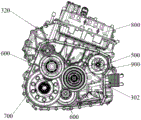
图5为本申请实施例3中混合动力电驱动总成的整体结构图。FIG. 5 is an overall structural diagram of the hybrid electric drive assembly in Embodiment 3 of the present application.

图6为图5的混合动力电驱动总成拆除端盖后的结构示意图。FIG. 6 is a schematic structural view of the hybrid electric drive assembly in FIG. 5 after the end cover is removed.

图7为图5的混合动力电驱动总成拆除右壳体后的结构示意图。FIG. 7 is a schematic structural view of the hybrid electric drive assembly in FIG. 5 after the right housing is removed.

附图标记说明:10-导油管,11-出油孔,12-出油口;20-导油件;30-衬套;40-执行机构,41-齿毂,42-结合齿,S1-第一执行机构,S2-第二执行机构;50-第一挡位齿轮,51-齿圈部,52-连接部;60-第二挡位齿轮;70-卡簧;80-轴套。Explanation of reference numerals: 10-oil guide pipe, 11-oil outlet hole, 12-oil outlet; 20-oil guide member; 30-bush; 40-actuator, 41-gear hub, 42-coupling tooth, S1- First actuator, S2-second actuator; 50-first gear, 51-ring gear, 52-connection; 60-second gear; 70-circlip; 80-sleeve.

100-行星排;110-太阳轮轴,111-第一中空腔,1111-储油腔,1112-扩孔段,112-第四导油孔,113-轴承安装槽;120-行星架,121-行星架轴,122-连接板,123-行星轮轴,124-集油腔,1241-大孔段,1242-小孔段,125-第一导油孔,126-第二导油孔,1261-轴向导油孔,1262-径向导油孔,127-第三导油孔;130-太阳轮;140-行星轮;150-内齿圈;160-润滑通道;171-行星轮轴承;172-第一行星架轴承;173-第二行星架轴承;174-中间轴承;175-第一支撑轴承;176-第二支撑轴承;177a-用于安装第一挡位齿轮的滚针轴承,177b-用于安装内齿圈轴的滚针轴承,177c-用于安装第二挡位齿轮的滚针轴承;178-推力轴承;179-球轴承。100-Planet row; 110-Sun gear shaft, 111-First hollow cavity, 1111-Oil storage chamber, 1112-Reaming section, 112-Fourth oil guide hole, 113-Bearing installation groove; 120-Planet carrier, 121- Planet carrier shaft, 122-connecting plate, 123-planetary wheel shaft, 124-oil collection chamber, 1241-large hole section, 1242-small hole section, 125-first oil guide hole, 126-second oil guide hole, 1261- Axial oil guide hole, 1262-radial oil guide hole, 127-third oil guide hole; 130-sun gear; 140-planetary gear; 150-internal gear; 160-lubrication channel; 171-planetary wheel bearing; 172-the first 1 planet carrier bearing; 173-second planet carrier bearing; 174-intermediate bearing; 175-first support bearing; 176-second support bearing; 177c-needle roller bearing used to install the second gear gear; 178-thrust bearing; 179-ball bearing.

200-内齿圈轴,201-内孔;210-轴套部;220-罩部,221-齿套部,222-挡板部,223-内花键;230-第一安装位;240-装配位,241-内孔壁;250-第二安装位;260-限位结构,261-卡簧槽,262-端面,263-凸边,264-孔肩;270-导油孔;280-导油槽。200-internal gear shaft, 201-inner hole; 210-shaft sleeve; 220-cover, 221-gear sleeve, 222-baffle, 223-inner spline; 230-first installation position; 240- Assembly position, 241-inner hole wall; 250-second installation position; 260-limiting structure, 261-circlip groove, 262-end face, 263-bulge, 264-hole shoulder; 270-oil guide hole; 280- Oil guide groove.

1000-混合动力电驱动总成;300-壳体总成;301-进油通道;302-轴齿安装腔;303-电机安装腔;310-右壳体;320-左壳体,321-中间板;330-端盖。400-电机总成,401-发电机,402-驱动电机;410-转子,411-第二中空腔;500-换挡机构总成;600-中间轴齿总成;700-差速器总成;800-控制器总成;900-输入轴总成。1000-hybrid electric drive assembly; 300-housing assembly; 301-oil inlet channel; 302-shaft gear installation cavity; 303-motor installation cavity; 310-right housing; 320-left housing, 321-middle plate; 330 - end cap. 400-motor assembly, 401-generator, 402-drive motor; 410-rotor, 411-second hollow cavity; 500-shift mechanism assembly; 600-intermediate shaft gear assembly; 700-differential assembly ; 800-controller assembly; 900-input shaft assembly.

具体实施方式Detailed ways

为了使本申请所属技术领域中的技术人员更清楚地理解本申请,下面结合附图,通过具体实施例对本申请技术方案作详细描述。In order to enable those skilled in the technical field to which the application belongs to understand the application more clearly, the technical solutions of the application will be described in detail below through specific embodiments in conjunction with the accompanying drawings.

实施例1:Example 1:

本发明实施例提供一种内齿圈轴200,该内齿圈轴200整体可套设于行星排100外,充当行星排100的一部分,该内齿圈轴200通过支撑轴承安装于壳体总成300上,其上可设置多个构件的安装位。具体参见图1和图2,该内齿圈轴200包括轴套部210和罩部220,轴套部210为轴套结构,能套装于轴上,例如行星排100的太阳轮轴110或行星架轴121。轴套部210的轴向尺寸较长,其上可沿轴向设置若干用于安装执行机构40的第一安装位230,或者用于设置支撑轴承的装配位240、用于设置齿轮的第二安装位250。罩部220与行星排100的内齿圈150传动连接,作为行星排100的一部分参与行星排100的运行,罩部220的内孔型面以及外型面均可作为用于设置支撑轴承的装配位240或用于设置齿轮的第二安装位250。由此,通过设置该内齿圈轴200,可以同时集成行星排100传动功能、执行机构40安装、换挡齿轮安装以及必要的轴向限位功能,从而极大的提供电驱动系统的集成度,缩减电驱动的功能体积,使得设备有该内齿圈轴200的电驱动系统具备更灵活的布置和搭载性能。The embodiment of the present invention provides an inner ring gear shaft 200, which can be sleeved outside the planetary row 100 as a whole, and serves as a part of the planetary row 100. The inner ring gear shaft 200 is installed on the housing assembly through a support bearing Into 300, the mounting positions of multiple components can be set on it. 1 and 2, the ring gear shaft 200 includes a sleeve portion 210 and a cover portion 220. The sleeve portion 210 is a sleeve structure and can be sleeved on the shaft, such as the sun gear shaft 110 of the planetary row 100 or the planet carrier. Shaft 121. The axial dimension of the sleeve part 210 is relatively long, and several first installation positions 230 for installing the actuator 40 can be arranged on it in the axial direction, or the assembly positions 240 for setting the support bearing, and the second installation positions for setting the gear. Install bit 250. The cover part 220 is in drive connection with the ring gear 150 of the planetary row 100, and participates in the operation of the planetary row 100 as a part of the planetary row 100. The inner hole profile and the outer profile of the cover part 220 can be used as an assembly for setting the support bearing bit 240 or a second mounting bit 250 for setting gear. Therefore, by setting the ring gear shaft 200, the transmission function of the planetary row 100, the installation of the actuator 40, the installation of the shift gear and the necessary axial limit function can be integrated at the same time, thereby greatly improving the integration of the electric drive system. , reducing the functional volume of the electric drive, so that the electric drive system equipped with the ring gear shaft 200 has more flexible layout and loading performance.

该内齿圈轴200可以是一体式结构,即轴套部210和罩部220通过铸造或机加工等一体成型。该内齿圈轴200也可以是分体式结构,轴套部210和罩部220可以通过焊接、粘接、螺接等方式固定连接。本实施例中,该内齿圈轴200为铸造成型的一体式结构,然后通过机加工加工出内外型面,其材质可以是不锈钢、铸铝等金属材料。The ring gear shaft 200 may be a one-piece structure, that is, the sleeve part 210 and the cover part 220 are integrally formed by casting or machining. The ring gear shaft 200 can also be a split structure, and the sleeve part 210 and the cover part 220 can be fixedly connected by means of welding, bonding, screwing and the like. In this embodiment, the ring gear shaft 200 is a one-piece structure formed by casting, and then the inner and outer surfaces are processed by machining, and its material can be metal materials such as stainless steel and cast aluminum.

内齿圈轴200的罩部220罩设于行星排100的主体部分上,行星排100的太阳轮130、行星轮140、内齿圈150均位于罩部220的内孔中。具体的,罩部220包括齿套部221和挡板部222,挡板部222的内环连接轴套部210、外环连接于齿套部221。齿套部221的结构与轴套部210类似,均为轴套结构,齿套部221与行星排100的内齿圈150传动连接。挡板部222可以是环形平板、环形球壳或者由多跟连杆构成的立体结构,挡板部222的具体结构形态本申请不做限制。轴套部210、挡板部222、齿套部221可以是一体式结构,或者通过焊接、粘接、螺接等方式固定连接。齿套部221与内齿圈150可以是一体式结构或者键连接,从而实现动力传动,使得整个内齿圈轴200能够跟随行星排100的内齿圈150共同转动。The cover part 220 of the inner ring gear shaft 200 covers the main part of the planetary row 100 , and the sun gear 130 , the planetary gear 140 and the ring gear 150 of the planetary row 100 are all located in the inner hole of the cover part 220 . Specifically, the cover part 220 includes a gear sleeve part 221 and a baffle part 222 , the inner ring of the baffle part 222 is connected to the shaft sleeve part 210 , and the outer ring is connected to the gear sleeve part 221 . The structure of the sleeve portion 221 is similar to that of the sleeve portion 210 , both of which are sleeve structures, and the sleeve portion 221 is in transmission connection with the ring gear 150 of the planetary row 100 . The baffle part 222 may be an annular flat plate, an annular spherical shell, or a three-dimensional structure composed of multi-link connecting rods, and the specific structure of the baffle part 222 is not limited in this application. The shaft sleeve portion 210, the baffle plate portion 222, and the gear sleeve portion 221 may be of an integrated structure, or be fixedly connected by means of welding, bonding, screwing, or the like. The ring gear part 221 and the ring gear 150 may be in one-piece structure or keyed to realize power transmission, so that the ring gear shaft 200 can rotate together with the ring gear 150 of the planetary row 100 .

具体的,本实施例中,齿套部221与内齿圈150通过花键连接,齿套部221的内型面设置内花键223,内齿圈150的内型面为与行星轮140啮合的齿、外型面为外花键,内齿圈150沿轴向卡入内花键223中,内齿圈150的一侧通过挡板部222的内部的端面262轴向限位,在齿套部221的内花键223设有卡簧槽261,卡簧槽261中安装卡簧70后,该卡簧70可对内齿圈150的另一侧进行轴向限位。由此确保齿套部221与内齿圈150不会发生轴向相对移动。并且卡簧70为可拆卸结构,不会影响内齿圈150的安装和拆卸。Specifically, in this embodiment, the gear sleeve part 221 is connected to the ring gear 150 through a spline, and the inner surface of the gear sleeve part 221 is provided with an inner spline 223, and the inner shape surface of the ring gear 150 is for meshing with the planetary gear 140. The teeth and outer surface of the ring gear are external splines, and the inner ring gear 150 is snapped into the inner spline 223 in the axial direction. The inner spline 223 of the part 221 is provided with a snap ring groove 261 , and after the snap ring 70 is installed in the snap ring slot 261 , the snap ring 70 can axially limit the other side of the ring gear 150 . In this way, it is ensured that the gear sleeve portion 221 and the ring gear 150 will not move relative to each other in the axial direction. And the snap ring 70 is a detachable structure, which will not affect the installation and disassembly of the ring gear 150 .

内齿圈轴200上的多个构件安装位主要包括用于安装执行机构40的第一安装位230、用于设置支撑轴承的装配位240和用于设置齿轮的第二安装位250。其中执行机构40可以是同步器或离合器,执行机构40可以是空套于内齿圈轴200上,或者是与内齿圈轴200固定连接或传动连接。支撑轴承用于将该内齿圈轴200安装于壳体总成300上。齿轮可以是挡位齿轮或者是仅起传动作用的传动齿轮,齿轮可以是空套于内齿圈轴200上,或者是与内齿圈轴200固定连接或传动连接。在其他实施例中,还可视具体情况在内齿圈轴200设置其他构件安装位,例如用于安装挡油件的构件安装位、用于设置传感器的构件安装位等。The multiple component installation positions on the ring gear shaft 200 mainly include a first installation position 230 for installing the actuator 40 , an assembly position 240 for setting a support bearing, and a second installation position 250 for setting a gear. The actuator 40 may be a synchronizer or a clutch, and the actuator 40 may be sleeved on the ring gear shaft 200 , or fixedly connected or driven connected with the ring gear shaft 200 . Support bearings are used to mount the ring gear shaft 200 on the housing assembly 300 . The gear can be a gear gear or a transmission gear that only plays a transmission role. The gear can be vacantly sleeved on the ring gear shaft 200 , or be fixedly connected or drivingly connected with the ring gear shaft 200 . In other embodiments, other component mounting positions may also be provided on the inner ring gear shaft 200 according to specific conditions, such as a component mounting position for installing an oil deflector, a component mounting position for installing a sensor, and the like.

上述构件安装位中,第一安装位230均设于轴套部210上,主要是因为执行机构40动作是需要一定的轴向空间,而轴套部210相比于罩部220的轴向尺寸更大,能够满足执行机构40动作所需要的轴向空间;另一方面,轴套部210套设于行星排100的太阳轮轴110或行星架轴121上,罩部220套设于行星排100的太阳轮130、行星轮140、内齿圈150上,轴套部210相比于罩部220的径向尺寸更小,便于布置执行机构40。Among the installation positions of the above-mentioned components, the first installation position 230 is all set on the sleeve part 210, mainly because the action of the actuator 40 requires a certain axial space, and the axial size of the sleeve part 210 compared with the cover part 220 Larger, able to meet the axial space required for the action of the actuator 40; On the sun gear 130 , the planetary gear 140 , and the ring gear 150 , the sleeve part 210 has a smaller radial dimension than the cover part 220 , which is convenient for arranging the actuator 40 .

本实施例中,执行机构40的作用是改变行星排100的传动比,例如将行星排100的内齿圈150与太阳轮轴110接合共同转动、将内齿圈150与行星架接合共同转动、将行星架与太阳轮轴110接合共同转动、将内齿圈150锁定、将太阳轮130锁定、将行星轮140锁定等。本实施例中,第一安装位230为键连接结构,使得执行机构40与内齿圈轴200传动连接,由于内齿圈轴200与行星排100的内齿圈150传动连接,因此执行机构40可以改变内齿圈150的运动情况,例如将内齿圈150与太阳轮轴110或行星架接合,或者将内齿圈150锁定。In this embodiment, the function of the actuator 40 is to change the transmission ratio of the planetary row 100, for example, the ring gear 150 of the planetary row 100 is engaged with the sun gear shaft 110 to rotate together, the ring gear 150 is engaged with the planet carrier to rotate together, The planet carrier is engaged with the sun gear shaft 110 to rotate together, lock the ring gear 150 , lock the sun gear 130 , lock the planet gear 140 and so on. In this embodiment, the first installation position 230 is a key connection structure, so that the actuator 40 is in transmission connection with the ring gear shaft 200. Since the ring gear shaft 200 is in transmission connection with the ring gear 150 of the planetary row 100, the actuator 40 The movement of the ring gear 150 can be changed, such as engaging the ring gear 150 with the sun gear shaft 110 or the planet carrier, or locking the ring gear 150 .

在第一安装位230上设有用于对执行机构40轴向限位的限位结构260,防止执行机构40与内齿圈轴200之间发生轴向相对转动。具体在本实施例中,执行机构40与内齿圈轴200采用花键连接,也即第一安装位230的键连接结构采用外花键,执行机构40的齿毂41和/或结合齿42的内圈设置内花键。针对花键连接,执行机构40与内齿圈轴200采用卡簧70限位,对应的限位结构260为设于外花键的卡簧槽261,卡簧70在执行机构40的齿毂41和/或结合齿42安装到位后卡在卡簧槽261中。A limiting structure 260 for axially limiting the actuator 40 is provided on the first mounting position 230 to prevent axial relative rotation between the actuator 40 and the ring gear shaft 200 . Specifically, in this embodiment, the actuator 40 is connected to the ring gear shaft 200 by a spline, that is, the key connection structure of the first mounting position 230 adopts an external spline, and the gear hub 41 and/or the coupling teeth 42 of the actuator 40 The inner ring is provided with inner splines. For the spline connection, the actuator 40 and the ring gear shaft 200 are limited by the retaining spring 70, and the corresponding limiting structure 260 is the retaining spring groove 261 provided on the external spline. And/or the coupling tooth 42 is stuck in the snap ring groove 261 after being installed in place.

对于用于设置支撑轴承的装配位240和用于设置齿轮的第二安装位250,支撑轴承和齿轮的工作形式是转动,不需要发生轴向移动,因此可根据实际需要设置在罩部220和/或轴套部210上。通常,一根轴需要至少两个轴承安装固定,因此装配位240的数量同样为两个以上,两个以上装配位240沿轴向间隔分布,也即齿套部221和轴套部210均设有装配位240。具体的,罩部220的装配位240为齿套部221的内孔壁241,轴套部210的装配位240为光杆段,支撑轴承与内孔壁241以及光杆段均过盈配合。齿套部221的装配位240与内齿圈150的安装处之间设有用于对对应的支撑轴承轴向限位的限位结构260,该处的限位结构260可采用端面限位(例如轴肩限位、凸台限位)或者卡簧限位。参见图2,本实施例中,齿套部221的内孔壁241与内花键223之间形成孔肩,通过孔肩对内孔壁241上安装的支撑轴承进行轴向限位。For the assembly position 240 for setting the support bearing and the second installation position 250 for setting the gear, the working form of the support bearing and the gear is rotation, and no axial movement needs to occur, so it can be installed on the cover part 220 and / or on the sleeve portion 210 . Usually, a shaft requires at least two bearings to be installed and fixed, so the number of assembly positions 240 is also more than two, and more than two assembly positions 240 are distributed at intervals along the axial direction, that is, both the gear sleeve part 221 and the shaft sleeve part 210 are provided with There are assembly bits 240. Specifically, the assembly position 240 of the cover part 220 is the inner hole wall 241 of the tooth sleeve part 221, the assembly position 240 of the shaft sleeve part 210 is the polished rod section, and the support bearing is interference fit with the inner hole wall 241 and the polished rod section. Between the assembly position 240 of the gear sleeve part 221 and the installation position of the inner ring gear 150, there is a limit structure 260 for axially limiting the corresponding support bearing. Shaft shoulder limit, boss limit) or circlip limit. Referring to FIG. 2 , in this embodiment, a shoulder is formed between the inner hole wall 241 of the tooth sleeve portion 221 and the inner spline 223 , and the supporting bearing installed on the inner hole wall 241 is axially limited by the hole shoulder.

在某些实施例中,轴套部210的装配位240上设有轴套80,一方面可以弥补支撑轴承与光杆段的直径差,另一方面可以用于周围结构件的轴向限位,轴套80与对应的光杆段过盈压装,支撑轴承过盈安装与轴套80上。轴套80用于周围结构件的轴向限位时,周围结构件同样对轴套80起到轴向限位的作用。In some embodiments, the assembly position 240 of the sleeve part 210 is provided with a sleeve 80, which can compensate for the diameter difference between the support bearing and the polished rod section on the one hand, and can be used to limit the axial direction of the surrounding structural parts on the other hand. The shaft sleeve 80 is press-fitted with the corresponding polished rod section with interference, and the support bearing is installed with the shaft sleeve 80 with interference. When the shaft sleeve 80 is used to limit the axial position of the surrounding structural parts, the surrounding structural parts also play the role of axially limiting the shaft sleeve 80 .

本实施例中,内齿圈轴200适用于具有挡位的行星齿轮变速器中,例如四挡变速器至少需要两个执行机构40和至少两个挡位齿轮。以适用于发明申请“一种混合动力驱动系统”(公开号CN113232501A)为例,该混合动力驱动系统通过两个同步器和两个挡位齿轮实现发动机四挡,两个同步器和两个挡位齿轮分别记为:第一执行机构S1、第二执行机构S2、第一挡位齿轮50和第二挡位齿轮60。第一执行机构S1、第二执行机构S2均为同步器,第一挡位齿轮50为大齿圈,实现发动机三挡和发动机四挡;第二挡位齿轮60为小齿圈,实现发动机一挡和发动机二挡。In this embodiment, the ring gear shaft 200 is suitable for a planetary gear transmission with gears, for example, a four-speed transmission requires at least two actuators 40 and at least two gears. Take "a hybrid drive system" (publication number CN113232501A) applicable to the invention application as an example, the hybrid drive system realizes the fourth gear of the engine through two synchronizers and two gears, two synchronizers and two gears The gears are respectively marked as: the first actuator S1, the second actuator S2, the first gear 50 and the second gear 60. Both the first actuator S1 and the second actuator S2 are synchronizers. The first gear gear 50 is a large ring gear to realize the third gear and the fourth gear of the engine; the second gear gear 60 is a small gear ring to realize the engine one gear gear and engine second gear.

第一挡位齿轮50和第二挡位齿轮60分别安装于两个第二安装位250,由于第一挡位齿轮50和第二挡位齿轮60均空套于内齿圈轴200上,因此第一挡位齿轮50和第二挡位齿轮60的内孔均安装有轴承,例如滚珠轴承,如图3所示。在其他实施例中,若齿轮与内齿圈轴200传动连接,则不需要设置轴承。为了降低内齿圈轴200的轴向长度,齿套部221和轴套部210均设有第二安装位250,也即第一挡位齿轮50通过轴承空套于齿套部221上,第二挡位齿轮60通过轴承空套于轴套部210上。The first gear gear 50 and the second gear gear 60 are respectively installed in the two second installation positions 250, since the first gear gear 50 and the second gear gear 60 are both hollowly sleeved on the ring gear shaft 200, so The inner holes of the first gear 50 and the second gear 60 are equipped with bearings, such as ball bearings, as shown in FIG. 3 . In other embodiments, if the gear is in transmission connection with the ring gear shaft 200 , no bearing is required. In order to reduce the axial length of the ring gear shaft 200, both the sleeve part 221 and the sleeve part 210 are provided with a second installation position 250, that is, the first gear gear 50 is idly sleeved on the sleeve part 221 through a bearing, and the second The second gear 60 is idly sleeved on the sleeve part 210 through a bearing.

该内齿圈轴200的第二安装位250设有用于对齿轮或齿轮的轴承轴向限位的限位结构260,该限位结构260可以为限位凸台、限位台阶或用于安装卡簧70的凹槽。若限位结构260用于对轴承进行轴向限位,则通常选择限位凸台、限位台阶、结构端面限位;若限位结构260用于对齿轮进行轴向限位,齿轮与内齿圈轴200传动连接,例如花键连接,则通常选择卡簧70进行轴向限位。The second mounting position 250 of the ring gear shaft 200 is provided with a limiting structure 260 for axially limiting the gear or the bearing of the gear. The limiting structure 260 can be a limiting boss, a limiting step, or a Groove of snap ring 70. If the limiting structure 260 is used for axially limiting the bearing, usually a limiting boss, a limiting step, and a structural end face are selected; if the limiting structure 260 is used for axially limiting the gear, the gear and the inner The transmission connection of the ring gear shaft 200 , such as a spline connection, generally selects the retaining spring 70 to limit the axial direction.

在限位结构260的设计上,为了方便执行机构40、齿轮、轴承等结构件的安装,本实施例中,轴套部210的外型面设计为阶梯轴,具体是自远行星排端至近行星排端,轴套部210的外径呈增大趋势,各结构件逐个套装于轴套部210。阶梯轴自身可形成若干用于轴向定位的限位台阶,此外,该阶梯轴的上还设置有若干凸边263,用于对轴套80、轴承等进行轴向限位。In the design of the limit structure 260, in order to facilitate the installation of structural parts such as the actuator 40, gears, bearings, etc., in this embodiment, the outer surface of the sleeve part 210 is designed as a stepped shaft, specifically from the far end of the planetary row to the near end. At the end of the planetary row, the outer diameter of the sleeve portion 210 tends to increase, and each structural member is fitted on the sleeve portion 210 one by one. The stepped shaft itself can form several limiting steps for axial positioning. In addition, the stepped shaft is also provided with several convex edges 263 for axially limiting the shaft sleeve 80 and bearings.

本实施例中,内齿圈轴200适用于具有四挡的行星齿轮变速器中,因此第一安装位230、装配位240、第二安装位250均设有两个。为保证两个第一安装位230上安装的两个执行机构40具有足够的轴向拨动空间,两个第一安装位230分布于轴套部210的两端,需要说明的是,第一安装位230可以安装执行机构40的所有构件,也可以仅用于安装执行机构40的部分构件,例如仅安装同步器的齿毂41或者单侧的结合齿42。为了缩小内齿圈轴200的轴向尺寸,提高设置有该内齿圈轴200的混动变速箱的搭载性能,本实施例中,两个装配位240和两个第二安装位250均分别设于轴套部210和罩部220上。In this embodiment, the ring gear shaft 200 is suitable for a planetary gear transmission with four gears, so there are two first installation positions 230 , two second installation positions 240 , and two second installation positions 250 . In order to ensure that the two actuators 40 installed on the two first installation positions 230 have sufficient axial movement space, the two first installation positions 230 are distributed at both ends of the sleeve part 210. It should be noted that the first The installation position 230 can be used for installing all the components of the actuator 40 , or only for installing some components of the actuator 40 , such as only installing the gear hub 41 of the synchronizer or the coupling tooth 42 on one side. In order to reduce the axial dimension of the ring gear shaft 200 and improve the carrying performance of the hybrid gearbox provided with the ring gear shaft 200, in this embodiment, the two assembly positions 240 and the two second installation positions 250 are respectively It is provided on the sleeve part 210 and the cover part 220 .

由于本实施例的内齿圈轴200上需要安装多个轴承、齿轮,需要保证该多个轴承、齿轮的润滑需求,具体可以采用飞溅润滑或主动润滑的方式,由于内齿圈轴200各个轴承、齿轮布置紧凑,相互形成轴向限位的效果,因此仅通过外部飞溅的润滑油恐难以达到预期的润滑效果,因此,本实施例采用主动润滑方案。Since multiple bearings and gears need to be installed on the ring gear shaft 200 of this embodiment, it is necessary to ensure the lubrication requirements of the multiple bearings and gears. Specifically, splash lubrication or active lubrication can be used. Since each bearing of the ring gear shaft 200 1. The arrangement of the gears is compact and mutually forms the effect of axial limit. Therefore, it may be difficult to achieve the expected lubricating effect only through the lubricating oil splashed from the outside. Therefore, this embodiment adopts the active lubricating scheme.

具体的,轴套部210上设有至少一个贯通轴套部210套壁的导油孔270,导油孔270通常沿周向设置多个,位于同一横截面的多个导油孔270为一组,则轴套部210上沿其轴向可以设置多组导油孔270。本实施例中,轴套部210的外型面设有连通于导油孔270的导油槽280,导油槽280与一组导油孔270均连通,导油槽280的具体数量根据实际需要而定。导油槽280为内凹的凹槽,通过设置导油槽280可以将导油孔270流出的润滑油沿周向均匀分布,另外,由于导油槽280为凹槽,该凹槽还可作为内齿圈轴200外型面机加工时的退刀槽。Specifically, the sleeve part 210 is provided with at least one oil guide hole 270 penetrating through the wall of the sleeve part 210. Usually, a plurality of oil guide holes 270 are arranged along the circumferential direction, and multiple oil guide holes 270 located in the same cross-section are one multiple groups of oil guide holes 270 may be provided on the sleeve portion 210 along its axial direction. In this embodiment, the outer surface of the shaft sleeve part 210 is provided with an oil guide groove 280 connected to the oil guide hole 270, and the oil guide groove 280 is connected with a group of oil guide holes 270, and the specific number of the oil guide groove 280 is determined according to actual needs. . The oil guide groove 280 is a concave groove. By setting the oil guide groove 280, the lubricating oil flowing out of the oil guide hole 270 can be evenly distributed in the circumferential direction. In addition, since the oil guide groove 280 is a groove, the groove can also be used as an inner ring gear The undercut groove when machining the outer profile of the shaft 200.

此外,在某些实施例中,套部220上也可设置导油孔270,导油孔270可选择设置在齿套部221和/或挡板部222上,便于润滑油进出罩部220的内孔。参见图2,本实施例中,挡板部222上可以设置若干导油孔270,该导油孔270设置为沿飞溅方向向外倾斜,便于行星排100转动时飞溅的润滑油从导油孔270中甩出,润滑内齿圈轴200外部的结构件。In addition, in some embodiments, an oil guide hole 270 may also be provided on the cover part 220, and the oil guide hole 270 may be optionally provided on the tooth cover part 221 and/or the baffle part 222, so as to facilitate the lubricating oil entering and leaving the cover part 220. Bore. Referring to Fig. 2, in this embodiment, a number of oil guide holes 270 can be provided on the baffle part 222, and the oil guide holes 270 are arranged to be inclined outward along the splashing direction, so that the splashed lubricating oil can pass through the oil guide holes when the planetary row 100 rotates. 270, lubricate the structural parts outside the ring gear shaft 200.

实施例2:Example 2:

基于同样的发明构思,本实施例提供一种输入轴总成900,该输入轴总成900可应用于混合动力电驱动总成或者普通的变速箱中,该输入轴总成900与发动机的输出轴连接。具体参见图3和图4,输入轴总成900包括行星排100、至少一个执行机构40、至少一个支撑轴承、至少一个齿轮和上述实施例1的内齿圈轴200。该输入轴总成900的至少一个执行机构40安装于内齿圈轴200的至少一个第一安装位230上;该输入轴总成900的至少一个支撑轴承设置于内齿圈轴200的至少一个装配位240上;该输入轴总成900的至少一个齿轮设置于内齿圈轴200的至少一个第二安装位250上。也就是说,内齿圈轴200的第一安装位230、装配位240和第二安装位250的数量与待安装的执行机构40、支撑轴承、齿轮的数量相匹配。通常,一根轴需要两个支撑轴承安装支撑;执行机构40的数量与挡位设计正相关,例如一个执行机构40实现两个挡位;齿轮的数量与变速器设计有关,齿轮具体可以是与执行机构40相配合实现换挡,也可以是作为传动齿轮与其他齿轮相配合实现速比调整。Based on the same inventive concept, this embodiment provides an input shaft assembly 900, which can be applied to a hybrid electric drive assembly or a common gearbox, and the input shaft assembly 900 is connected to the output of the engine shaft connection. Referring specifically to FIGS. 3 and 4 , the input shaft assembly 900 includes a planetary row 100 , at least one actuator 40 , at least one support bearing, at least one gear and the ring gear shaft 200 of the first embodiment above. At least one actuator 40 of the input shaft assembly 900 is installed on at least one first installation position 230 of the ring gear shaft 200; at least one support bearing of the input shaft assembly 900 is arranged on at least one of the ring gear shaft 200 On the assembly position 240 ; at least one gear of the input shaft assembly 900 is disposed on at least one second installation position 250 of the ring gear shaft 200 . That is to say, the number of the first installation location 230 , the installation location 240 and the second installation location 250 of the inner ring gear shaft 200 matches the number of the actuator 40 , supporting bearings and gears to be installed. Usually, a shaft requires two supporting bearings to be installed and supported; the number of actuators 40 is positively related to the gear design, for example, one actuator 40 realizes two gears; the number of gears is related to the design of the transmission, and the gears can be specifically related to the execution The mechanism 40 cooperates to realize gear shifting, and can also be used as a transmission gear to cooperate with other gears to realize speed ratio adjustment.

该输入轴总成900由于同时集成了执行机构40、行星排100和齿轮,并且上述结构通过内齿圈轴200集成为一体,集成度高,并且轴向尺寸小。内齿圈轴200内部空间安装行星排100、外部空间安装执行机构40、轴承和齿轮,使得该输入轴总成900在装配时能够作为一个独立的供货集与壳体进行装配,降低了装配难度。Since the input shaft assembly 900 integrates the actuator 40, the planetary row 100 and the gear at the same time, and the above-mentioned structure is integrated through the ring gear shaft 200, the integration degree is high and the axial dimension is small. The planetary row 100 is installed in the internal space of the ring gear shaft 200, and the actuator 40, bearings and gears are installed in the external space, so that the input shaft assembly 900 can be assembled with the housing as an independent supply set during assembly, reducing the assembly cost. difficulty.

本实施例中,该输入轴总成900为可实现发动机四挡的单行星排100变速机构分总成。执行机构40设置有两个,分别为第一执行机构S1和第二执行机构S2,第一执行机构S1和第二执行机构S2可根据需要采用同步器(单边或双边)或离合器。支撑轴承同样设置两个,分别为第一支撑轴承175和第二支撑轴承176,第一支撑轴承175和第二支撑轴承176可采用滚珠轴承、滚针轴承、推力轴承等,本实施例采用滚珠轴承。齿轮同样设置两个,分别为第一挡位齿轮50和第二挡位齿轮60,第一挡位齿轮50和第二挡位齿轮60均与执行机构40配合,实现换挡。In this embodiment, the input shaft assembly 900 is a sub-assembly of a single planetary row 100 transmission mechanism capable of realizing the fourth gear of the engine. There are two actuators 40, namely the first actuator S1 and the second actuator S2. The first actuator S1 and the second actuator S2 can use synchronizers (unilateral or bilateral) or clutches as required. There are also two support bearings, which are respectively the first support bearing 175 and the second support bearing 176. The first support bearing 175 and the second support bearing 176 can adopt ball bearings, needle bearings, thrust bearings, etc., and the present embodiment adopts ball bearings. bearings. Two gears are also provided, namely the first gear gear 50 and the second gear gear 60 respectively, both of the first gear gear 50 and the second gear gear 60 cooperate with the actuator 40 to realize gear shifting.

具体的,第一执行机构S1和第二执行机构S2分布于轴套部210的两端。第一执行机构S1/第二执行机构S2可根据实际需要设置为可选择地连接太阳轮轴110与内齿圈轴200、可选择地连接行星架轴121与内齿圈轴200、可选择地连接内齿圈轴200与第一挡位齿轮50或可选择地连接内齿圈轴200与第二挡位齿轮60。本实施例中,第一执行机构S1采用同步器,具有齿毂41和两侧的结合齿42,第一执行机构S1的齿毂41与第一安装位230传动连接;第一执行机构S1的一侧的结合齿42与第一挡位齿轮50固定连接;第一执行机构S1的另一侧的结合齿42与第二挡位齿轮60固定连接,第一执行机构S1用于将内齿圈轴200可选地与第一挡位齿轮50或第二挡位齿轮60连接。第二执行机构S2同样采用同步器,具有齿毂41和两侧的结合齿42,第二执行机构S2的齿毂41与行星排100的太阳轮轴110传动连接,第二执行机构S2的一侧的结合齿42与轴套部210传动连接,第二执行机构S2的另一侧的结合齿42与壳体总成300固定连接,第二执行机构S2用于将太阳轮轴110可选地与内齿圈轴200或壳体总成300连接,实现行星排100不同的速比输出。为了提高该输入轴总成900的轴向承载能力,第二执行机构S2的齿毂41与壳体总成300之间设有推力轴承,该推力轴承套装于太阳轮轴110上。Specifically, the first actuator S1 and the second actuator S2 are distributed at both ends of the sleeve part 210 . The first actuator S1/second actuator S2 can be set to selectively connect the sun gear shaft 110 and the ring gear shaft 200, selectively connect the planet carrier shaft 121 and the ring gear shaft 200, and selectively connect according to actual needs. The ring gear shaft 200 is connected to the first gear 50 or alternatively connects the ring gear shaft 200 to the second gear 60 . In this embodiment, the first actuator S1 adopts a synchronizer, which has a gear hub 41 and coupling teeth 42 on both sides, and the gear hub 41 of the first actuator S1 is in transmission connection with the first installation position 230; The coupling teeth 42 on one side are fixedly connected to the first gear 50; the coupling teeth 42 on the other side of the first actuator S1 are fixedly connected to the second gear 60, and the first actuator S1 is used to connect the ring gear The shaft 200 is optionally connected with the first range gear 50 or the second range gear 60 . The second actuator S2 also adopts a synchronizer, which has a gear hub 41 and coupling teeth 42 on both sides. The gear hub 41 of the second actuator S2 is in transmission connection with the sun gear shaft 110 of the planetary row 100. One side of the second actuator S2 The coupling tooth 42 of the second actuator S2 is connected to the shaft sleeve part 210 in transmission, and the coupling tooth 42 on the other side of the second actuator S2 is fixedly connected to the housing assembly 300. The second actuator S2 is used to optionally connect the sun gear shaft 110 to the inner The ring gear shaft 200 or the housing assembly 300 are connected to realize different speed ratio outputs of the planetary row 100 . In order to improve the axial bearing capacity of the input shaft assembly 900 , a thrust bearing is provided between the gear hub 41 of the second actuator S2 and the housing assembly 300 , and the thrust bearing is sleeved on the sun gear shaft 110 .

具体的,第一支撑轴承175和第二支撑轴承176分别安装于轴套部210和罩部220上,第一支撑轴承175设于罩部220的内孔中,第二支撑轴承176通过轴套80设于第一执行机构S1和第二执行机构S2之间,第一支撑轴承175和第二支撑轴承176由于主要起到支撑内齿圈轴200的作用,因此可均采用滚珠轴承。第一支撑轴承175通过第一安装位230的端面262,即罩部220的第一安装位230与支撑位所形成的孔肩264轴向限位;第二支撑轴承176通过轴套80上设置的凸台轴向限位。第一支撑轴承175的内环和第二支撑轴承176的外环分别与壳体总成300的轴承安装孔过盈配合。Specifically, the first support bearing 175 and the second support bearing 176 are installed on the shaft sleeve part 210 and the cover part 220 respectively, the first support bearing 175 is arranged in the inner hole of the cover part 220, and the second support bearing 176 passes through the shaft sleeve 80 is located between the first actuator S1 and the second actuator S2, and the first support bearing 175 and the second support bearing 176 mainly support the inner ring gear shaft 200, so both ball bearings can be used. The first support bearing 175 is axially limited by the end face 262 of the first installation position 230, that is, the hole shoulder 264 formed by the first installation position 230 and the support position of the cover part 220; the second support bearing 176 is set on the sleeve 80 The axial limit of the boss. The inner ring of the first support bearing 175 and the outer ring of the second support bearing 176 are respectively interference fit with the bearing installation holes of the housing assembly 300 .

具体的,第一挡位齿轮50通过滚针轴承177a空套于罩部220上,第二挡位齿轮60通过滚针轴承177c空套于轴套部210上、且位于第一执行机构S1与第二支撑轴承176之间,第一挡位齿轮50和第二挡位齿轮60均为齿圈,其内孔中安装的轴承为滚针轴承,第一挡位齿轮50和第二挡位齿轮60均可相对于内齿圈轴200自由转动。Specifically, the first gear gear 50 is vacantly sleeved on the cover portion 220 through the needle bearing 177a, and the second gear gear 60 is idly sleeved on the sleeve portion 210 through the needle bearing 177c, and is located between the first actuator S1 and Between the second supporting bearings 176, both the first gear gear 50 and the second gear gear 60 are ring gears, and the bearings installed in their inner holes are needle bearings, and the first gear gear 50 and the second gear gear 60 can freely rotate relative to the ring gear shaft 200.

本实施例中,第一挡位齿轮50为大齿圈,第一挡位齿轮50既要满足能够套装于罩部220上的直径要求,又要满足与安装于轴套部210上的第一执行机构S1连接,因此,第一挡位齿轮50具体设置为包括齿圈部51和连接部52,齿圈部51与内齿圈轴200的齿套部221结构相似,均为轴套结构,连接部52与内齿圈轴200的挡板部222结构相似均为环形板结构。齿圈部51和连接部52可以是一体成型结构,或者通过焊接、螺纹紧固件连接固定。齿圈部51通过滚针轴承177a空套于罩部220上,该轴承通过罩部220外型面上设置的凸边263轴向限位。连接部52与第一执行机构S1的一侧的结合齿42固定连接,连接部52与第一执行机构S1的该结合齿42可以是一体成型、焊接固定或者传动连接。第二挡位齿轮60与第一执行机构S1的另一侧的结合齿42固定连接,第二挡位齿轮60与第一执行机构S1的该结合齿42可以是一体成型、焊接固定或者传动连接。第二挡位齿轮60通过第二支撑轴承176的轴套80轴向限位。In this embodiment, the first gear gear 50 is a large ring gear, and the first gear gear 50 must not only meet the diameter requirements of being able to fit on the cover part 220, but also meet the first gear ring installed on the sleeve part 210. The actuator S1 is connected. Therefore, the first gear gear 50 is specifically configured to include a ring gear part 51 and a connecting part 52. The ring gear part 51 is similar in structure to the gear sleeve part 221 of the inner ring gear shaft 200, both of which are sleeve structures. The structure of the connecting portion 52 is similar to that of the baffle portion 222 of the ring gear shaft 200 and both are annular plate structures. The ring gear part 51 and the connecting part 52 can be integrally formed, or connected and fixed by welding or threaded fasteners. The ring gear part 51 is vacantly sleeved on the cover part 220 through the needle bearing 177a, and the bearing is axially limited by the flange 263 provided on the outer surface of the cover part 220. The connection part 52 is fixedly connected to the coupling tooth 42 on one side of the first actuator S1, and the connection part 52 and the coupling tooth 42 of the first actuator S1 can be integrally formed, welded or connected by transmission. The second gear 60 is fixedly connected to the coupling teeth 42 on the other side of the first actuator S1, and the second gear 60 and the coupling teeth 42 of the first actuator S1 can be integrally formed, fixed by welding or connected by transmission. . The second gear gear 60 is axially limited by the sleeve 80 of the second support bearing 176 .

为了进一步提高该输入轴总成900的轴向承载能力,如图3所示,连接部52与罩部220之间设有推力轴承178,具体是连接部52与挡板部222之间设有推力轴承178。也就是说,第一挡位齿轮50通过滚针轴承177a和推力轴承178套在内齿圈轴200上,通过推力轴承178以及挡板部222外部的端面262轴向限位。内齿圈轴200的罩部220上设置有贯通壁厚的导油孔270,使得行星排100中飞溅的润滑油能够通过罩部220上的导油孔270进入第一挡位齿轮50与罩部220之间的缝隙中,润滑其中的滚针轴承177a和推力轴承178。In order to further improve the axial bearing capacity of the input shaft assembly 900, as shown in FIG. Thrust bearing 178. That is to say, the first gear gear 50 is sleeved on the ring gear shaft 200 through the needle bearing 177 a and the thrust bearing 178 , and axially limited by the thrust bearing 178 and the end surface 262 outside the baffle portion 222 . The cover part 220 of the ring gear shaft 200 is provided with an oil guide hole 270 through the wall thickness, so that the lubricating oil splashed in the planetary row 100 can enter the first gear gear 50 and the cover through the oil guide hole 270 on the cover part 220. In the gap between the parts 220, the needle bearing 177a and the thrust bearing 178 therein are lubricated.

参见图3,该输入轴总成900中,行星排100的太阳轮轴110或行星架轴121与发动机连接,实现发动机动力输入,内齿圈轴200套设于行星排100的用于输出的行星架轴121或太阳轮轴110上,例如行星排100采用太阳轮轴110输入,则内齿圈轴200和行星架轴121作为输出,内齿圈轴200相应套装于行星架轴121上。若行星排100采用行星架轴121输入,则内齿圈轴200和太阳轮轴110作为输出,内齿圈轴200相应套装于太阳轮轴110上。内齿圈轴200的罩部220与行星排100的内齿圈150传动连接,具体可采用一体成型、焊接或键连接。内齿圈轴200、行星架轴121、太阳轮轴110在工作时需要转动,并且某些工况下存在转速差,因此需要在内齿圈轴200与太阳轮轴110或行星架轴121之间安装轴承,轴承的内圈套设于太阳轮轴110或行星架轴121上,内齿圈轴200套设于轴承的外圈上。本实施例中,内齿圈轴200通过两个滚针轴承177b套装于太阳轮轴110上。Referring to FIG. 3 , in the input shaft assembly 900, the sun gear shaft 110 or the planet carrier shaft 121 of the planetary row 100 is connected to the engine to realize engine power input, and the ring gear shaft 200 is sleeved on the output planet of the planetary row 100 On the carrier shaft 121 or the sun gear shaft 110 , for example, the planetary row 100 adopts the sun gear shaft 110 as input, then the ring gear shaft 200 and the planet carrier shaft 121 are output, and the ring gear shaft 200 is correspondingly sleeved on the planet carrier shaft 121 . If the planetary row 100 is input by the planet carrier shaft 121 , then the ring gear shaft 200 and the sun gear shaft 110 are output, and the ring gear shaft 200 is correspondingly fitted on the sun gear shaft 110 . The cover portion 220 of the inner ring gear shaft 200 is in transmission connection with the inner ring gear 150 of the planetary row 100 , and specifically can be integrally formed, welded or keyed. The ring gear shaft 200, the planet carrier shaft 121, and the sun gear shaft 110 need to rotate during work, and there is a speed difference under certain working conditions, so it is necessary to install between the ring gear shaft 200 and the sun gear shaft 110 or the planet carrier shaft 121 For the bearing, the inner ring of the bearing is sleeved on the sun gear shaft 110 or the planet carrier shaft 121 , and the inner ring gear shaft 200 is sleeved on the outer ring of the bearing. In this embodiment, the ring gear shaft 200 is sleeved on the sun gear shaft 110 through two needle bearings 177b.

在某些实施例中,该输入轴总成900应用于混合动力电驱动总成、且具有发动机驱动和电机驱动的并联模式,该输入轴总成900的行星排100的太阳轮轴110或行星架轴121与电机总成400连接,例如行星排100采用行星架轴121输入,内齿圈轴200和太阳轮轴110作为输出,内齿圈轴200套装于太阳轮轴110上,则太阳轮轴110上设有用于与电机总成400传动连接的连接结构;若行星排100采用太阳轮轴110输入,内齿圈轴200和行星架轴121作为输出,则内齿圈轴200上设有用于与电机总成400传动连接的连接结构。本实施例中,该输入轴总成900的行星排100采用行星架轴121输入,内齿圈轴200和太阳轮轴110作为输出的技术方案,内齿圈轴200套设于太阳轮轴110上。In some embodiments, the input shaft assembly 900 is applied to a hybrid electric drive assembly and has a parallel mode of engine driving and motor driving, the sun gear shaft 110 or the planetary carrier of the planetary row 100 of the input shaft assembly 900 The shaft 121 is connected with the motor assembly 400. For example, the planetary row 100 adopts the planetary carrier shaft 121 as input, the ring gear shaft 200 and the sun gear shaft 110 as output, and the ring gear shaft 200 is set on the sun gear shaft 110, and the sun gear shaft 110 is provided with There is a connection structure for transmission connection with the motor assembly 400; if the planetary row 100 adopts the sun gear shaft 110 as input, and the ring gear shaft 200 and the planet carrier shaft 121 are used as output, then the ring gear shaft 200 is provided with a motor assembly. The connection structure of the 400 transmission connection. In this embodiment, the planetary row 100 of the input shaft assembly 900 uses the planet carrier shaft 121 as the input, and the ring gear shaft 200 and the sun gear shaft 110 as the output technical solution, and the ring gear shaft 200 is sleeved on the sun gear shaft 110 .

行星排100是功率分流的主要零件,行星排100的润滑是保证该输入轴总成900正常运行的重要条件,行星排100的主要润滑需求在于行星轮轴承171,一方面行星轮轴承171数量多,分布广,另一方面,由于行星轮轴承171的安装位置是位于行星架120所围区域中,并且位于行星轮140与行星轮轴123之间,因此受行星轮140、行星架120的阻挡,润滑油难以进入行星轮轴承171安装处,故而行星轮轴承171容易产生烧蚀,影响整个行星排100的使用。The planetary row 100 is the main part of the power distribution. The lubrication of the planetary row 100 is an important condition to ensure the normal operation of the input shaft assembly 900. The main lubrication requirement of the planetary row 100 lies in the planetary wheel bearing 171. On the one hand, the number of planetary wheel bearings 171 is large , widely distributed, on the other hand, since the installation position of the planet wheel bearing 171 is located in the area surrounded by the planet carrier 120, and between the planet wheel 140 and the planet wheel shaft 123, it is blocked by the planet wheel 140 and the planet carrier 120, It is difficult for lubricating oil to enter the installation place of the planetary wheel bearing 171 , so the planetary wheel bearing 171 is prone to ablation, which affects the use of the entire planetary row 100 .

为了改善行星排100的润滑情况,参阅图4,本实施例中,行星排100设有润滑通道160,行星排100的太阳轮轴110设有沿轴向贯通的第一中空腔111,太阳轮轴110可以是与行星排100的太阳轮130一体成型,或者键连接,本实施例中太阳轮轴110与太阳轮130一体成型。行星排100的行星架120设有集油腔124,第一中空腔111、集油腔124和润滑通道160依次连通,并且润滑通道160的出口朝向行星排100的行星轮轴承171。为了方便润滑太阳轮轴110外部的结构,太阳轮轴110上设有若干与第一中空腔111相连通的第四导油孔112,其中一个第四导油孔112的出口朝向太阳轮轴110与内齿圈轴200之间的轴承。In order to improve the lubrication of the planetary row 100, referring to Fig. 4, in the present embodiment, the planetary row 100 is provided with a lubricating passage 160, and the sun gear shaft 110 of the planetary row 100 is provided with a first hollow cavity 111 penetrating in the axial direction, and the sun gear shaft 110 It can be integrally formed with the sun gear 130 of the planetary row 100 , or connected with a key. In this embodiment, the sun gear shaft 110 and the sun gear 130 are integrally formed. The planet carrier 120 of the planetary row 100 is provided with an oil collection chamber 124 , the first hollow chamber 111 , the oil collection chamber 124 and the lubricating channel 160 communicate in sequence, and the outlet of the lubricating channel 160 faces the planet wheel bearing 171 of the planetary row 100 . In order to facilitate the lubrication of the external structure of the sun gear shaft 110, the sun gear shaft 110 is provided with a number of fourth oil guide holes 112 that communicate with the first hollow cavity 111, and the outlet of one of the fourth oil guide holes 112 faces the sun gear shaft 110 and the inner gear. Bearings between ring shafts 200.

具体的,行星架120的润滑通道160可以是开设于行星架120基材中的油道,也可以是由外部元件合围形成的油道,满足能够将润滑油送入行星轮轴承171的安装处即可。本实施例中,该行星轮轴承171为滚针轴承,具体可以是满滚针轴承或钢保持架滚针轴承。该行星轮轴承171采用双列滚针轴承,中间设置有垫片,垫片在径向上要与行星轮轴123形成间隙,保证润滑油可以进入滚针轴承中,润滑滚针轴承的滚子表面。Specifically, the lubricating channel 160 of the planet carrier 120 can be an oil channel opened in the base material of the planet carrier 120, or an oil channel surrounded by external components, which can meet the requirement of sending lubricating oil into the installation place of the planet wheel bearing 171. That's it. In this embodiment, the planet wheel bearing 171 is a needle roller bearing, specifically, it may be a full needle roller bearing or a steel cage needle roller bearing. The planet wheel bearing 171 adopts a double-row needle roller bearing, and a gasket is arranged in the middle. The gasket will form a gap with the planet wheel shaft 123 in the radial direction to ensure that lubricating oil can enter the needle roller bearing and lubricate the roller surface of the needle roller bearing.

请参阅图4,本实施例中,行星架120包括依次连接的行星架轴121、连接板122和若干行星轮轴123,行星轮140套在行星轮轴123上,行星轮140与行星轮轴123之间安装有行星轮轴承171,行星轮140两侧分别通过齿轮与太阳轮130的齿轮和内齿圈150的齿轮进行啮合。行星架轴121位于连接板122的中心,行星轮轴123以行星架轴121为中心、沿周向均匀分布。行星架轴121与连接板122可以通过螺纹紧固件、卡扣结构等可拆卸连接,或者焊接固定,或者行星架轴121与连接板122为一体式结构,本实施例中,行星架轴121通过过盈压装在连接板122上。连接板122和行星轮轴123也可以通过螺纹紧固件、卡扣结构等可拆卸连接,或者焊接固定,或者连接板122和行星轮轴123为一体式结构,本申请不做限制。行星架120的整体外部形状、轮廓本申请同样不做限制,例如行星架120可以采用笼式结构。Please refer to Fig. 4, in the present embodiment, the planet carrier 120 comprises the planet carrier shaft 121 connected in sequence, the connection plate 122 and several planet wheel shafts 123, the planet wheel 140 is sleeved on the planet wheel shaft 123, between the planet wheel 140 and the planet wheel shaft 123 Planetary gear bearings 171 are installed, and the two sides of the planetary gear 140 mesh with the gears of the sun gear 130 and the gears of the ring gear 150 respectively through gears. The planet carrier shaft 121 is located at the center of the connecting plate 122 , and the planet wheel shafts 123 are centered on the planet carrier shaft 121 and evenly distributed along the circumferential direction. The planetary carrier shaft 121 and the connecting plate 122 can be detachably connected by threaded fasteners, buckle structures, etc., or fixed by welding, or the planetary carrier shaft 121 and the connecting plate 122 are of an integrated structure. In this embodiment, the planetary carrier shaft 121 It is mounted on the connecting plate 122 by interference pressing. The connecting plate 122 and the planetary wheel shaft 123 can also be detachably connected by threaded fasteners, buckle structures, etc., or fixed by welding, or the connecting plate 122 and the planetary wheel shaft 123 have an integrated structure, which is not limited in this application. The overall external shape and outline of the planetary carrier 120 are not limited in this application, for example, the planetary carrier 120 may adopt a cage structure.

具体的,行星架轴121设有连通的集油腔124和第一导油孔125,集油腔124位于行星架轴121的中心,优选与行星架轴121共轴线。行星轮轴123设有第二导油孔126,第二导油孔126的出口朝向行星排100的行星轮轴承171。连接板122外侧设有导油件20,第一导油孔125、导油件20与连接板122之间空隙、第二导油孔126依次连通,构成润滑通道160。导油件20将集油腔124中在离心作用下由第一导油孔125中甩出的润滑油引导至第二导油孔126。Specifically, the planet carrier shaft 121 is provided with a connected oil collection chamber 124 and a first oil guide hole 125 , the oil collection chamber 124 is located at the center of the planet carrier shaft 121 , preferably coaxial with the planet carrier shaft 121 . The planet wheel shaft 123 is provided with a second oil guide hole 126 , and the outlet of the second oil guide hole 126 faces the planet wheel bearing 171 of the planet row 100 . An oil guiding member 20 is provided outside the connecting plate 122 , the first oil guiding hole 125 , the gap between the oil guiding member 20 and the connecting plate 122 , and the second oil guiding hole 126 communicate in sequence to form a lubricating channel 160 . The oil guiding member 20 guides the lubricating oil thrown out from the first oil guiding hole 125 in the oil collecting chamber 124 to the second oil guiding hole 126 under centrifugal action.

本实施例中,行星架轴121与太阳轮轴110之间设有中间轴承174,中间轴承174采用推力轴承,能够承受较大的轴向力,太阳轮轴110的其中一端通过该推力轴承抵在行星架轴121上,推力轴承能够满足行星排100在某些工况下行星架120与太阳轮轴110之间存在转速差的工作需求。该中间轴承174具体位于太阳轮轴110的端部,在某些实施例中,可在太阳轮轴110的端部设置一个内凹的轴承安装槽113,该轴承安装槽113与第一中空腔111连通,由此使得中间轴承174的内部空隙与第一中空腔111连通,第一中空腔111中的润滑油能够进入中间轴承174。In this embodiment, an intermediate bearing 174 is provided between the planetary carrier shaft 121 and the sun gear shaft 110. The intermediate bearing 174 adopts a thrust bearing, which can bear a relatively large axial force. On the carrier shaft 121 , the thrust bearing can meet the working requirement that there is a speed difference between the planetary carrier 120 and the sun gear shaft 110 under certain working conditions of the planetary row 100 . The intermediate bearing 174 is specifically located at the end of the sun gear shaft 110. In some embodiments, a concave bearing installation groove 113 may be provided at the end of the sun gear shaft 110, and the bearing installation groove 113 communicates with the first hollow cavity 111. , so that the internal space of the intermediate bearing 174 communicates with the first hollow cavity 111 , and the lubricating oil in the first hollow cavity 111 can enter the intermediate bearing 174 .

第二导油孔126可以是沿行星轮轴123径向和/或轴向延伸的通道,也可以是沿行星轮轴123周向延伸的通道,也就是说,第二导油孔126可以是轴向直通道、径向直通道、斜向直通道、曲线通道等,本申请不做限制。具体的,本实施例中,第二导油孔126包括沿行星轮轴123轴向延伸的轴向导油孔1261和至少一个沿行星轮轴123径向延伸的径向导油孔1262,径向导油孔1262的出口构成润滑通道160的出口。径向导油孔1262的数量根据行星轮轴承171的尺寸而定,通常设置为两个以上,两个以上径向导油孔1262的出口沿行星轮轴123的周向表面间隔、均匀分布,例如第二导油孔126包括沿行星轮轴123轴向延伸的轴向导油孔1261和四个沿行星轮轴123径向延伸的径向导油孔1262,四个径向导油孔1262互呈90°分布,保证油品到达行星轮轴承171,避免由于行星轮轴承171润滑不充分导致整个行星排100烧结。在某些实施例中,轴向导油孔1261的入口设置为扩口,扩口优选圆扩口,降低流阻。沿沿行星轮轴123的轴向,该扩口的孔径自中部向端部逐渐增加,便于润滑油进入轴向导油孔1261。The second oil guide hole 126 may be a channel extending radially and/or axially along the planet wheel shaft 123, or a channel extending circumferentially along the planet wheel shaft 123, that is to say, the second oil guide hole 126 may be an axial Straight passages, radial straight passages, oblique straight passages, curved passages, etc., are not limited in this application. Specifically, in this embodiment, the second oil guide hole 126 includes an axial oil guide hole 1261 extending axially along the planetary wheel shaft 123 and at least one radial oil guide hole 1262 extending radially along the planetary wheel shaft 123. The radial oil guide hole 1262 The outlet of the lubricating channel 160 constitutes the outlet. The number of radial oil guide holes 1262 depends on the size of the planetary wheel bearing 171, and is usually set to more than two. The outlets of more than two radial oil guide holes 1262 are spaced and evenly distributed along the circumferential surface of the planetary wheel shaft 123, for example, the second The oil guide hole 126 includes an axial oil guide hole 1261 extending axially along the planetary wheel shaft 123 and four radial oil guide holes 1262 extending radially along the planetary wheel shaft 123. The four radial oil guide holes 1262 are distributed at 90° to each other to ensure oil The product reaches the planetary wheel bearing 171, avoiding the sintering of the entire planetary row 100 due to insufficient lubrication of the planetary wheel bearing 171. In some embodiments, the inlet of the axial oil guide hole 1261 is configured as a flaring, preferably a circular flaring, to reduce flow resistance. Along the axial direction of the planetary wheel shaft 123 , the diameter of the flaring hole gradually increases from the middle to the end, so that lubricating oil can enter the axial oil hole 1261 .

在某些实施例中,行星架120上安装有第一行星架轴承172,第一行星架轴承172设置于润滑通道160中,第一行星架轴承172的内部空隙与润滑通道160连通,供润滑油流通。参见图3和图4,该第一行星架轴承172安装于行星架轴121上,并且靠近行星架120的连接板122,该第一行星架轴承172为推力轴承,推力轴承的松环与连接板122接触,推力轴承的紧环与外部固定构件(例如用于安装行星排100的壳体总成300)连接和/或接触,使得行星排轴向稳定。在松环与紧环之间则可形成供润滑油流通的通道,润滑油在松环与紧环之间流通时还可对推力轴承的滚子进行润滑。当然,在其他实施例中,还可将第一行星架轴承172设置在行星架120的其他位置,与润滑通道160完全分离,避免第一行星架轴承172的内部结构产生流阻。In some embodiments, the first planet carrier bearing 172 is installed on the planet carrier 120, and the first planet carrier bearing 172 is arranged in the lubricating channel 160, and the internal space of the first planet carrier bearing 172 communicates with the lubricating channel 160 for lubrication. oil flow. 3 and 4, the first planet carrier bearing 172 is installed on the planet carrier shaft 121 and is close to the connecting plate 122 of the planet carrier 120. The first planet carrier bearing 172 is a thrust bearing, and the loose ring of the thrust bearing is connected to The plate 122 is in contact, and the tight ring of the thrust bearing is connected and/or in contact with an external fixed member (such as the housing assembly 300 for mounting the planetary row 100 ), so that the planetary row is axially stable. A channel for the circulation of lubricating oil can be formed between the loose ring and the tight ring. When the lubricating oil circulates between the loose ring and the tight ring, it can also lubricate the rollers of the thrust bearing. Of course, in other embodiments, the first planetary carrier bearing 172 can also be arranged at other positions of the planetary carrier 120 , completely separated from the lubricating channel 160 , so as to avoid flow resistance generated by the internal structure of the first planetary carrier bearing 172 .

在某些实施例中,为了提高行星架120的转动稳定性,行星架轴121上还安装有第二行星架轴承173,第二行星架轴承173采用滚针轴承,例如行星架120通过第二行星架轴承173安装于壳体总成300(具体是右壳体310)中。第二行星架轴承173在工作时同样需要润滑,为此,行星架轴121设有与集油腔124连通的第三导油孔127,第三导油孔127的出口朝向第二行星架轴承173。总的来说,集油腔124要求能够容纳导油管10的近行星排100端,并且存储一定油液以输送至第三导油孔127。考虑到第二行星架轴承173所需润滑油相较于行星轮轴承171少,为了保证行星轮轴承171供油充足,在某些实施例中,集油腔124呈阶梯孔的结构,其大孔段1241用于容纳导油管10的近行星排100端,小孔段1242与第三导油孔127连通。In some embodiments, in order to improve the rotation stability of the planet carrier 120, a second planet carrier bearing 173 is installed on the planet carrier shaft 121, and the second planet carrier bearing 173 adopts a needle bearing, for example, the planet carrier 120 passes through the second The planet carrier bearing 173 is installed in the housing assembly 300 (specifically, the right housing 310 ). The second planet carrier bearing 173 also needs to be lubricated during operation. For this reason, the planet carrier shaft 121 is provided with a third oil guide hole 127 communicating with the oil collection chamber 124, and the outlet of the third oil guide hole 127 faces the second planet carrier bearing. 173. In general, the oil collection cavity 124 is required to be able to accommodate the end of the oil guide pipe 10 near the planetary row 100 and store a certain amount of oil for delivery to the third oil guide hole 127 . Considering that the lubricating oil required by the second planetary carrier bearing 173 is less than that of the planetary wheel bearing 171, in order to ensure sufficient oil supply for the planetary wheel bearing 171, in some embodiments, the oil collection chamber 124 has a stepped hole structure, the size of which is The hole section 1241 is used to accommodate the end of the oil guide pipe 10 near the planetary row 100 , and the small hole section 1242 communicates with the third oil guide hole 127 .

由于行星排100的行星架120、太阳轮轴110等存在轴向的制造和加工误差,太阳轮轴110与行星架120之间通常会存在一定的间隙,在某些极限的情况流入此部位的润滑油会通过该间隙大量的泄漏出去。为了解决上述问题,本实施例中,太阳轮轴110内嵌入导油管10,导油管10贯通安装于行星排100的太阳轮轴110内部,具体是贯通安装于第一中空腔111中,且导油管10的近行星排100端伸入于集油腔124,以将太阳轮轴110内的油导入到行星架的集油腔124中。通过设置导油管10,在轴向导油通道比较长的情况下,采用导油管10将润滑油从远行星排100端的润滑油入口将油品传递到行星排100的行星架120中,可以避免由于太阳轮轴110高速运转所形成的离心力将油甩出无法到达行星排100的情况,并且导油管10的近行星排端伸入于集油腔124中,能够降低太阳轮轴110与行星架120之间间隙处的润滑油的泄漏量。润滑油在润滑通道160中流通,并最终流动至行星轮轴承171处,润滑各个行星轮140的轴承,保证该轴承的充分油量,避免整个行星排100的烧蚀导致的整车安全问题。Due to axial manufacturing and processing errors in the planet carrier 120 and the sun gear shaft 110 of the planetary row 100, there is usually a certain gap between the sun gear shaft 110 and the planet carrier 120, and in some extreme cases, the lubricating oil that flows into this part A large amount will leak out through this gap. In order to solve the above problems, in this embodiment, the sun gear shaft 110 is embedded with the oil guide pipe 10, and the oil guide pipe 10 is installed through the inside of the sun gear shaft 110 of the planetary row 100, specifically installed through the first hollow cavity 111, and the oil guide pipe 10 The end near the planet row 100 protrudes into the oil collection chamber 124 to guide the oil in the sun gear shaft 110 into the oil collection chamber 124 of the planet carrier. By setting the oil guide pipe 10, in the case of a relatively long axial oil guide passage, the oil guide pipe 10 is used to transfer the lubricating oil from the lubricating oil inlet at the far end of the planetary row 100 to the planetary carrier 120 of the planetary row 100, which can avoid the The centrifugal force formed by the high-speed operation of the sun gear shaft 110 throws the oil out and cannot reach the planetary row 100, and the end of the oil guide pipe 10 near the planetary row extends into the oil collection chamber 124, which can reduce the gap between the sun gear shaft 110 and the planetary carrier 120. Leakage of lubricating oil in the gap. The lubricating oil circulates in the lubricating channel 160 and finally flows to the planetary wheel bearings 171 to lubricate the bearings of each planetary wheel 140 to ensure the sufficient amount of oil in the bearings and avoid vehicle safety problems caused by the ablation of the entire planetary row 100 .

导油管10上设有若干沿导油管10轴向和/或径向间隔分布的出油孔11。沿导游管的轴向,出油孔11通常设置有多个,并且各出油孔11的孔径、孔距均相同。位于同一轴向位置的出油孔11也可设置为多个,多个位于同一轴向位置的出油孔11沿周向间隔分布,使得油液能够均匀的流动至太阳轮轴110的第一中空腔111中。在导油管10的与轴承的安装位置所对应的轴向位置处还可额外开设出油孔11。The oil guide pipe 10 is provided with a plurality of oil outlet holes 11 distributed along the axial and/or radial intervals of the oil guide pipe 10 . Along the axial direction of the guide tube, there are usually a plurality of oil outlet holes 11, and the hole diameter and hole distance of each oil outlet hole 11 are the same. A plurality of oil outlet holes 11 located at the same axial position can also be provided, and the plurality of oil outlet holes 11 located at the same axial position are distributed at intervals along the circumferential direction, so that the oil can evenly flow to the first hollow of the sun gear shaft 110 cavity 111. An additional oil hole 11 can also be opened at the axial position of the oil guide pipe 10 corresponding to the installation position of the bearing.

在某些实施例中,导油管10的远行星排100端设有一个以上出油口12,由于出油口12开设于导油管10的管壁上,因此能够径向出油,降低阻力,便于油液进入润滑通道160。出油口12可以设置为具有开口的槽或者完整的孔,例如出油口12可以为U型槽或者圆孔。出油口12的数量本申请不做限制,例如出油口12的数量设置为3个,则3个出油口12的形状可以相同或者不同。In some embodiments, more than one oil outlet 12 is provided at the end of the outer planetary row 100 of the oil guide pipe 10. Since the oil outlet 12 is opened on the pipe wall of the oil guide pipe 10, it can discharge oil radially and reduce resistance. It is convenient for oil to enter the lubricating channel 160 . The oil outlet 12 can be configured as a groove with an opening or a complete hole, for example, the oil outlet 12 can be a U-shaped groove or a round hole. The number of oil outlets 12 is not limited in this application. For example, if the number of oil outlets 12 is set to three, the shapes of the three oil outlets 12 may be the same or different.

由于第一中空腔111的内径大于导油管10的外径,为了保证导油管10稳定安装于第一中空腔111中,在某些实施例中,导油管10上套设有至少一个衬套30,衬套30填充导油管10与第一中空腔111的腔壁之间的间隙。衬套30起支撑导油管10的作用,衬套30的材质为铜或复合塑料。Since the inner diameter of the first hollow chamber 111 is larger than the outer diameter of the oil guide pipe 10, in order to ensure that the oil guide pipe 10 is stably installed in the first hollow chamber 111, in some embodiments, at least one bushing 30 is sleeved on the oil guide pipe 10 , the bushing 30 fills the gap between the oil guide pipe 10 and the cavity wall of the first hollow cavity 111 . The bushing 30 plays the role of supporting the oil guide pipe 10, and the material of the bushing 30 is copper or composite plastic.

应用实例:Applications:

以适用于发明申请“一种混合动力驱动系统”(公开号CN113232501A)的输入轴总成900为例,输入轴总成900的结构如下:Taking the input shaft assembly 900 applicable to the invention application "a hybrid drive system" (publication number CN113232501A) as an example, the structure of the input shaft assembly 900 is as follows:

内齿圈轴200通过球轴承(第一支撑轴承175)以及安装于轴套80上的球轴承(第二支撑轴承176)分别支撑在壳体总成300的右壳体和左壳体上。在内齿圈轴200的外侧,大齿圈(第一挡位齿轮50)与第一同步器(第一执行机构S1)一侧的结合齿42焊接为一体,并通过滚针轴承177a以及推力轴承178套在内齿圈轴200上,以绕内齿圈轴200进行自由旋转,滚针轴承177a通过轴肩进行轴向限位,推力轴承178与内齿圈轴200端面262配合进行轴向限位。第一同步器的齿毂41通过内花键与内齿圈轴200的外花键相连进行扭矩的传递,并通过内齿圈轴200端面262以及安装于卡簧槽261中的卡簧70对第一同步器的齿毂41进行轴向限位;小齿圈(第二挡位齿轮60)与第一同步器的结合齿42焊接一体后通过滚针轴承177c安装于内齿圈轴200的轴套部210外侧,以绕内齿圈轴200自由旋转,小齿圈(第二挡位齿轮60)通过压装在内齿圈轴200轴径上的轴套80进行轴向限位,滚针轴承177c通过两侧轴肩进行轴向限位;第二同步器(第二执行机构S2)一侧的结合齿42通过内花键与内齿圈轴200的外花键连接,进行动力的传递,通过轴套80端面262以及安装于卡簧槽261内的卡簧70对第二同步器的结合齿42进行轴向限位。The ring gear shaft 200 is respectively supported on the right housing and the left housing of the housing assembly 300 through ball bearings (first support bearing 175 ) and ball bearings (second support bearing 176 ) installed on the sleeve 80 . On the outer side of the ring gear shaft 200, the large ring gear (the first gear gear 50) is welded together with the coupling teeth 42 on the side of the first synchronizer (the first actuator S1), and through the needle bearing 177a and the thrust The bearing 178 is set on the ring gear shaft 200 to freely rotate around the ring gear shaft 200, the needle bearing 177a is axially limited by the shaft shoulder, and the thrust bearing 178 cooperates with the end face 262 of the ring gear shaft 200 for axial positioning. limit. The gear hub 41 of the first synchronizer is connected to the external spline of the inner ring gear shaft 200 through the inner spline for torque transmission, and the pair of ring rings 70 installed in the ring groove 261 through the end face 262 of the ring gear shaft 200 The gear hub 41 of the first synchronizer is axially limited; the small ring gear (second gear gear 60) is welded together with the coupling tooth 42 of the first synchronizer and installed on the inner ring gear shaft 200 through the needle bearing 177c The outer side of the shaft sleeve part 210 is free to rotate around the ring gear shaft 200, and the pinion ring gear (second gear gear 60) is axially limited by the sleeve 80 press-fitted on the shaft diameter of the ring gear shaft 200. The needle bearing 177c is axially limited by the shaft shoulders on both sides; the coupling teeth 42 on one side of the second synchronizer (second actuator S2) are connected with the external splines of the inner ring gear shaft 200 through internal splines to perform power transmission. In transmission, the coupling tooth 42 of the second synchronizer is axially limited by the end surface 262 of the shaft sleeve 80 and the snap ring 70 installed in the snap ring groove 261 .

在内齿圈轴200内部,太阳轮轴110通过两个滚针轴承177b支撑在内齿圈轴200的内孔201中。第一同步器的齿毂41通过内花键与太阳轮轴110的外花键连接进行扭矩传递。太阳轮轴110的端部外花键与发电机401的电机轴的内花键连接,进行动力传递;电机轴通过球轴承179支撑在左壳体320的中间板321上。内齿圈150通过外花键与内齿圈轴200的内花键进行配合,与内齿圈轴200连成一体共同转动,内齿圈150通过内齿圈轴200端面262以及安装于卡簧槽261中的卡簧70进行轴向限位。内齿圈150通过与行星齿轮啮合将整个行星齿轮系统支撑在内齿圈轴200上。行星架120通过滚针轴承(第二行星架轴121承173)安装在右壳体上,行星架轴121通过过盈压装在行星架120两侧的连接板122上,行星轮140通过滚针轴承(行星轮轴承171)安装在行星架轴121上,行星轮140分别与内齿圈150和太阳轮130进行啮合。Inside the ring gear shaft 200 , the sun gear shaft 110 is supported in the inner bore 201 of the ring gear shaft 200 via two needle bearings 177 b. The gear hub 41 of the first synchronizer is connected with the external spline of the sun gear shaft 110 through an internal spline to transmit torque. The external spline of the end of the sun gear shaft 110 is connected with the internal spline of the motor shaft of the generator 401 for power transmission; the motor shaft is supported on the middle plate 321 of the left housing 320 through the ball bearing 179 . The inner ring gear 150 cooperates with the inner spline of the inner ring gear shaft 200 through the outer spline, and is connected with the inner ring gear shaft 200 to rotate together. The snap ring 70 in the groove 261 is axially limited. The ring gear 150 supports the entire planetary gear system on the ring gear shaft 200 by meshing with the planet gears. The planetary carrier 120 is installed on the right housing through a needle roller bearing (the second planetary carrier shaft 121 bears 173), the planetary carrier shaft 121 is mounted on the connecting plates 122 on both sides of the planetary carrier 120 through interference press, and the planetary gear 140 is rolled by Needle bearings (planetary gear bearings 171 ) are mounted on the carrier shaft 121 , and the planetary gears 140 mesh with the ring gear 150 and the sun gear 130 , respectively.

本实施例提供的输入轴总成900,整个行星排系统通过内齿圈轴200集成了第一执行机构S1和第二执行机构S2,1/2挡齿圈(第二挡位齿轮60)和3/4挡齿圈(第一挡位齿轮50),以及行星排100,并通过内侧支撑太阳轮轴110与电机相连,同时还集成了行星轮轴承171、执行机构40以及挡位齿轮及相关轴承等的润滑系统和电机的冷却系统。内齿圈轴200通过内外型面对各个系统提供支撑结构,并通过两侧第一支撑轴承175和第二支撑轴承176安装在壳体总成的左右壳体上,从而使得输入轴总成900能高度集成在一起,缩减了其他零件的布置安装位置和接口,使得搭载该输入轴总成900的电驱动系统的轴向和径向尺寸得以缩减,降低了该电驱动系统的功能体积,缩减成本并增强了其搭载性,使得产品更具竞争力。In the input shaft assembly 900 provided in this embodiment, the entire planetary train system integrates the first actuator S1 and the second actuator S2 through the ring gear shaft 200, the 1/2 gear ring gear (second gear 60) and The 3/4 gear ring gear (the first gear gear 50), and the planetary row 100 are connected to the motor through the inner support sun gear shaft 110, and also integrate the planetary gear bearing 171, the actuator 40, the gear gear and related bearings etc. lubrication system and motor cooling system. The inner ring gear shaft 200 provides support structures for each system through the inner and outer profiles, and is installed on the left and right housings of the housing assembly through the first support bearing 175 and the second support bearing 176 on both sides, so that the input shaft assembly 900 Can be highly integrated together, reducing the arrangement and installation positions and interfaces of other parts, so that the axial and radial dimensions of the electric drive system equipped with the input shaft assembly 900 can be reduced, reducing the functional volume of the electric drive system, reducing Cost and enhance its carrying capacity, making the product more competitive.

实施例3:Example 3:

基于同样的发明构思,本实施例提供一种混合动力电驱动总成1000,参阅图5至图7,混合动力电驱动总成1000包括壳体总成300和上述实施例2的输入轴总成900,输入轴总成900安装于壳体总成300内部。壳体总成300的结构根据输入轴总成900的结构而设计,满足输入轴总成900的安装需求即可,具体结构本申请不做限制。Based on the same inventive concept, this embodiment provides a hybrid electric drive assembly 1000, referring to Fig. 5 to Fig. 7, the hybrid electric drive assembly 1000 includes the housing assembly 300 and the input shaft assembly of the above-mentioned embodiment 2 900 , the input shaft assembly 900 is installed inside the casing assembly 300 . The structure of the housing assembly 300 is designed according to the structure of the input shaft assembly 900, and it only needs to meet the installation requirements of the input shaft assembly 900, and the specific structure is not limited in this application.

该混合动力电驱动总成1000还包括与壳体总成300连接的电机总成400,电机总成400可设置为仅包含一个电机,或者两个以上电机。电机总成400的至少一个电机的转子与行星排100的太阳轮轴110传动连接,实现动力在电机和行星排100之间的传递。具体的,本实施例中,电机总成400包括发电机401和驱动电机402,发电机401的转子与行星排100的太阳轮轴110传动连接,例如,发电机401的转子与行星排100的太阳轮轴110花键连接。The hybrid electric drive assembly 1000 also includes a motor assembly 400 connected to the housing assembly 300 , and the motor assembly 400 may be configured to include only one motor, or more than two motors. The rotor of at least one motor of the motor assembly 400 is in transmission connection with the sun gear shaft 110 of the planetary row 100 to realize power transmission between the motor and the planetary row 100 . Specifically, in this embodiment, the motor assembly 400 includes a generator 401 and a driving motor 402, and the rotor of the generator 401 is in transmission connection with the sun gear shaft 110 of the planetary row 100, for example, the rotor of the generator 401 is connected with the sun shaft 110 of the planetary row 100 The axle 110 is splined.

电机总成400可设置为集成及壳体总成300内部,或者电机总成400外置。为了提高混合动力电驱动总成1000的集成度,本实施例采用电机内置的方案,具体的,壳体总成300包括依次连接的右壳体310、左壳体320和端盖330,右壳体310与左壳体320合围成轴齿安装腔302,行星排100位于轴齿安装腔302中,行星架轴121通过第一行星架轴承172和第二行星架轴承173支撑在右壳体310上。左壳体320和端盖330合围成电机安装腔303,电机总成400位于电机安装腔303中。发电机401的转子410通过两个轴承支撑在左壳体320和端盖330上。The motor assembly 400 can be integrated and inside the housing assembly 300 , or the motor assembly 400 can be placed outside. In order to improve the integration of the hybrid electric drive assembly 1000, the present embodiment adopts a solution with a built-in motor. Specifically, the housing assembly 300 includes a right housing 310, a left housing 320 and an end cover 330 connected in sequence, and the right housing The body 310 and the left housing 320 form a shaft tooth installation cavity 302, the planet row 100 is located in the shaft tooth installation cavity 302, and the planet carrier shaft 121 is supported on the right housing 310 through the first planet carrier bearing 172 and the second planet carrier bearing 173. superior. The left housing 320 and the end cover 330 enclose a motor installation chamber 303 , and the motor assembly 400 is located in the motor installation chamber 303 . The rotor 410 of the generator 401 is supported on the left casing 320 and the end cover 330 through two bearings.

本实施例中,发电机401的转子410设有沿轴向贯通的第二中空腔411,进油通道301、第二中空腔411和第一中空腔111依次连通,电机总成400的转子410与行星排100同轴设置,壳体总成300的进油通道301引入的润滑油经第二中空腔411引入行星排100的第一中空腔111,行星排润滑结构的导油管10安装于第二中空腔411和第一中空腔111中,导油管10的远行星排100端与壳体总成300的进油通道301直接对接连通,导油管10的近行星排100端与行星架120的集油腔124直接对接连通。通过将电机总成400的转子410与行星排100内部油路串联,使得电机的转子充当润滑油的管路,使得润滑系统结构简化,提高了混合动力电驱动总成1000的集成度和整车搭载性。In this embodiment, the rotor 410 of the generator 401 is provided with a second hollow cavity 411 penetrating in the axial direction. Set coaxially with the planetary row 100, the lubricating oil introduced by the oil inlet channel 301 of the housing assembly 300 is introduced into the first hollow cavity 111 of the planetary row 100 through the second hollow cavity 411, and the oil guide pipe 10 of the planetary row lubrication structure is installed in the second hollow cavity 411. In the second hollow cavity 411 and the first hollow cavity 111, the end of the far planetary row 100 of the oil guide pipe 10 is directly connected to the oil inlet passage 301 of the housing assembly 300, and the end of the oil guide pipe 10 near the planetary row 100 is connected to the end of the planet carrier 120. The oil collection chamber 124 is directly butted in communication. By connecting the rotor 410 of the motor assembly 400 in series with the internal oil circuit of the planetary row 100, the rotor of the motor acts as a pipeline for lubricating oil, which simplifies the structure of the lubrication system and improves the integration of the hybrid electric drive assembly 1000 and the overall vehicle performance. Carryability.

端盖330中设有进油通道301,左壳体320的底部形成油底壳,润滑行星排100后的润滑油落入油底壳中,由外设的油泵提供泵油动力,使得润滑油在油底壳、进油通道301、导油管10、润滑通道160中循环流通。The end cover 330 is provided with an oil inlet passage 301, and the bottom of the left housing 320 forms an oil pan, and the lubricating oil after lubricating the planetary row 100 falls into the oil pan, and the external oil pump provides pumping power, so that the lubricating oil Circulate in the oil pan, the oil inlet channel 301 , the oil guide pipe 10 and the lubricating channel 160 .

由于发电机401的转子、行星排100的太阳轮轴110、内齿圈轴200均需要设置轴承进行安装支撑。为了增加轴承安装孔,本实施例中,左壳体320设有中间板321,中间板321呈罩体,与左壳体320通过螺纹紧固件或焊接固定连接。中间板321安装有用于支撑发电机401的转子410的球轴承179,如图3所示。为了进一步提高集成度,靠近发电机401的执行机构(具体为第二执行机构S2)的结合齿42与中间板321固定连接,具体可以是在中间板321上直接加工出该执行机构的结合齿。Since the rotor of the generator 401 , the sun gear shaft 110 of the planetary row 100 , and the ring gear shaft 200 all need to be provided with bearings for installation and support. In order to increase the bearing mounting holes, in this embodiment, the left housing 320 is provided with a middle plate 321, which is a cover body, and is fixedly connected with the left housing 320 by threaded fasteners or welding. The intermediate plate 321 is mounted with ball bearings 179 for supporting the rotor 410 of the generator 401 , as shown in FIG. 3 . In order to further improve integration, the coupling teeth 42 of the actuator (specifically the second actuator S2) close to the generator 401 are fixedly connected to the middle plate 321, specifically, the coupling teeth of the actuator can be directly processed on the middle plate 321 .

参见图7,在某些实施例中,该混合动力电驱动总成1000还包括换挡机构总成500、中间轴齿总成600、差速器总成700和控制器总成800,换挡机构总成500、中间轴齿总成600和差速器总成700均位于轴齿安装腔302中,换挡机构总成500和中间轴齿总成600与行星排100配合,实现变速和换挡功能,动力由差速器总成700输出至车轮轴系。控制器总成800安装于壳体总成300外部,用于控制电机总成400和/或换挡机构总成500工作,当然控制器总成800还可控制油泵以及该混合动力电驱动总成1000内部设置的一些传感器(温度传感器、压力传感器等)等电子设备的工作。换挡机构总成500、中间轴齿总成600、控制器总成800的具体内容可参照现有技术的相关公开,此处不展开说明。Referring to FIG. 7 , in some embodiments, the hybrid electric drive assembly 1000 further includes a shift mechanism assembly 500 , an intermediate shaft gear assembly 600 , a differential assembly 700 and a controller assembly 800 . The mechanism assembly 500, the intermediate shaft gear assembly 600 and the differential assembly 700 are all located in the shaft gear installation cavity 302, and the shifting mechanism assembly 500 and the intermediate shaft gear assembly 600 cooperate with the planetary row 100 to realize speed change and shifting. gear function, and the power is output from the differential gear assembly 700 to the wheel shafting. The controller assembly 800 is installed outside the shell assembly 300, and is used to control the operation of the motor assembly 400 and/or the shift mechanism assembly 500. Of course, the controller assembly 800 can also control the oil pump and the hybrid electric drive assembly Some sensors (temperature sensors, pressure sensors, etc.) and other electronic devices set inside the 1000 work. For the specific content of the shifting mechanism assembly 500 , the countershaft gear assembly 600 , and the controller assembly 800 , reference may be made to related publications in the prior art, and no further description is given here.

实施例4:Example 4:

基于同样的发明构思,本实施例提供一种车辆,包括上述实施例3的混合动力电驱动总成1000,也就是说,该车辆为混合动力车辆,由发动机和电机提供动力。由于该车辆配置有上述实施例3的混合动力电驱动总成1000,因此至少具有上述实施例3的技术方案所带来的所有有益效果,混合动力电驱动总成1000集成度高、体积小,可搭载于于不同车型车辆的发动机舱内。该车辆的其他未详述结构均可参照现有技术的相关公开,此处不展开说明。Based on the same inventive concept, this embodiment provides a vehicle, including the hybrid electric drive assembly 1000 of Embodiment 3 above, that is, the vehicle is a hybrid vehicle powered by an engine and an electric motor. Since the vehicle is equipped with the hybrid electric drive assembly 1000 of the above-mentioned embodiment 3, it at least has all the beneficial effects brought by the technical solution of the above-mentioned embodiment 3. The hybrid electric drive assembly 1000 is highly integrated and small in size. It can be installed in the engine compartment of vehicles of different models. For other unspecified structures of the vehicle, reference may be made to related publications in the prior art, and no further description is given here.

实施例5:Example 5:

基于同样的发明构思,本实施例提供一种车辆,包括上述实施例2的输入轴总成900,也就是说,该车辆可以为混合动力车辆或者纯电动车辆或者普通燃油车辆,由发动机和/或电机提供动力,上述实施例2的输入轴总成900能够实现换挡、变速的效果。该车辆的其他未详述结构均可参照现有技术的相关公开,此处不展开说明。Based on the same inventive concept, this embodiment provides a vehicle, including the input shaft assembly 900 of Embodiment 2 above, that is to say, the vehicle can be a hybrid vehicle or a pure electric vehicle or an ordinary fuel vehicle, and the Or the motor provides power, and the input shaft assembly 900 of the above-mentioned embodiment 2 can realize the effects of shifting and speed changing. For other unspecified structures of the vehicle, reference may be made to related publications in the prior art, and no further description is given here.

实施例6:Embodiment 6:

基于同样的发明构思,本实施例提供一种车辆,包括上述实施例1的内齿圈轴,也就是说,该车辆可以为混合动力车辆或者纯电动车辆或者普通燃油车辆,由发动机和/或电机提供动力,上述实施例1的内齿圈轴可以应用于该车辆的变速箱中,或者轮毂电机系统中。该车辆的其他未详述结构均可参照现有技术的相关公开,此处不展开说明。Based on the same inventive concept, this embodiment provides a vehicle, including the ring gear shaft of Embodiment 1 above. The motor provides power, and the ring gear shaft of Embodiment 1 above can be applied in the gearbox of the vehicle, or in the hub motor system. For other unspecified structures of the vehicle, reference may be made to related publications in the prior art, and no further description is given here.

尽管已描述了本申请的优选实施例,但本领域内的普通技术人员一旦得知了基本创造性概念,则可对这些实施例作出另外的变更和修改。所以,所附权利要求意欲解释为包括优选实施例以及落入本申请范围的所有变更和修改。While preferred embodiments of the present application have been described, additional changes and modifications to these embodiments can be made by those of ordinary skill in the art once the basic inventive concept is appreciated. Therefore, the appended claims are intended to be construed to cover the preferred embodiment and all changes and modifications which fall within the scope of the application.

显然,本领域的技术人员可以对本申请进行各种改动和变型而不脱离本申请的精神和范围。这样,倘若本申请的这些修改和变型属于本申请权利要求及其等同技术的范围之内,则本申请也意图包含这些改动和变型在内。Obviously, those skilled in the art can make various changes and modifications to the application without departing from the spirit and scope of the application. In this way, if these modifications and variations of the present application fall within the scope of the claims of the present application and their equivalent technologies, the present application is also intended to include these modifications and variations.

Claims (28)

1.一种内齿圈轴,其特征在于,用于套设于行星排外、且通过支撑轴承安装于壳体总成上;所述内齿圈轴包括:1. An inner ring gear shaft, characterized in that it is used to be sleeved on the planetary row and installed on the housing assembly through a support bearing; the inner ring gear shaft includes: 轴套部,用于套设于所述行星排的太阳轮轴或行星架轴上,所述轴套部上设有至少一个用于安装执行机构的第一安装位;The sleeve part is used to be sleeved on the sun gear shaft or the planet carrier shaft of the planetary row, and the sleeve part is provided with at least one first installation position for installing the actuator; 罩部,连接于所述轴套部,且用于与所述行星排的内齿圈传动连接;The cover part is connected to the shaft sleeve part and is used for transmission connection with the ring gear of the planetary row; 其中,所述罩部和/或所述轴套部设有至少一个用于设置所述支撑轴承的装配位;所述罩部和/或所述轴套部设有至少一个用于设置齿轮的第二安装位。Wherein, the cover portion and/or the sleeve portion are provided with at least one assembly position for setting the support bearing; the cover portion and/or the sleeve portion are provided with at least one mounting position for setting the gear The second installation position. 2.如权利要求1所述的内齿圈轴,其特征在于:所述罩部包括齿套部和挡板部,所述挡板部的内环连接所述轴套部、外环连接于所述齿套部。2. The inner ring gear shaft according to claim 1, characterized in that: the cover part includes a gear sleeve part and a baffle part, the inner ring of the baffle part is connected to the shaft sleeve part, and the outer ring is connected to the The gear sleeve part. 3.如权利要求2所述的内齿圈轴,其特征在于:所述齿套部与所述内齿圈为一体式结构或者键连接;所述轴套部、所述挡板部、所述齿套部为一体式结构。3. The inner ring gear shaft according to claim 2, characterized in that: the sleeve part and the ring gear are integrally constructed or connected by keys; the sleeve part, the baffle part, the The tooth cover part is an integral structure. 4.如权利要求3所述的内齿圈轴,其特征在于:所述齿套部与所述内齿圈通过花键连接;所述齿套部的内花键设有卡簧槽。4. The inner ring gear shaft according to claim 3, characterized in that: the gear sleeve part is connected to the inner gear ring through a spline; the inner spline of the gear sleeve part is provided with a retaining ring groove. 5.如权利要求2所述的内齿圈轴,其特征在于:所述齿套部和所述轴套部均设有所述装配位;所述齿套部的装配位为内孔壁,所述轴套部的装配位上设有用于安装所述支撑轴承的轴套。5. The inner ring gear shaft according to claim 2, characterized in that: the gear sleeve part and the shaft sleeve part are provided with the assembly position; the assembly position of the gear sleeve part is the inner hole wall, A shaft sleeve for installing the supporting bearing is arranged on the assembly position of the shaft sleeve part. 6.如权利要求5所述的内齿圈轴,其特征在于:所述齿套部的装配位与所述内齿圈的安装处之间设有用于对所述支撑轴承轴向限位的限位结构。6. The inner ring gear shaft according to claim 5, characterized in that: between the assembly position of the gear sleeve part and the installation place of the inner ring gear, there is an axial limiter for the support bearing. limit structure. 7.如权利要求2所述的内齿圈轴,其特征在于:所述齿套部和所述轴套部均设有所述第二安装位;所述第二安装位设有用于对所述齿轮或所述齿轮的轴承轴向限位的限位结构。7. The inner ring gear shaft according to claim 2, characterized in that: the gear sleeve portion and the shaft sleeve portion are both provided with the second installation position; the second installation position is provided for aligning the A limiting structure for axially limiting the gear or the bearing of the gear. 8.如权利要求1所述的内齿圈轴,其特征在于:所述第一安装位为键连接结构;所述第一安装位上设有用于对所述执行机构轴向限位的限位结构。8. The inner ring gear shaft according to claim 1, characterized in that: the first installation position is a key connection structure; the first installation position is provided with a limiter for axially limiting the actuator. bit structure. 9.如权利要求1-8中任一项所述的内齿圈轴,其特征在于:所述第一安装位、所述装配位、所述第二安装位均设有两个;两个所述第一安装位分布于所述轴套部的两端;两个所述装配位和两个所述第二安装位均分别设于所述轴套部和所述罩部上。9. The ring gear shaft according to any one of claims 1-8, characterized in that: there are two installation positions for the first installation position, the installation position and the second installation position; The first installation positions are distributed at both ends of the shaft sleeve; the two assembly positions and the two second installation positions are respectively provided on the shaft sleeve and the cover portion. 10.如权利要求1-8中任一项所述的内齿圈轴,其特征在于:所述轴套部和/或所述罩部上设有至少一个贯通所述轴套部套壁的导油孔;所述轴套部的外型面设有连通于所述导油孔的导油槽。10. The ring gear shaft according to any one of claims 1-8, characterized in that: the sleeve portion and/or the cover portion is provided with at least one hole penetrating through the sleeve wall of the sleeve portion. An oil guide hole; an oil guide groove connected to the oil guide hole is provided on the outer surface of the shaft sleeve. 11.一种输入轴总成,其特征在于,包括:用于连接发动机的行星排、至少一个执行机构、至少一个支撑轴承、至少一个齿轮和权利要求1-10中任一项所述的内齿圈轴;所述内齿圈轴套设于所述行星排的太阳轮轴或行星架轴上,且所述内齿圈轴的罩部与所述行星排的内齿圈传动连接;所述至少一个执行机构安装于所述至少一个第一安装位上;所述至少一个支撑轴承设置于所述至少一个装配位上;所述至少一个齿轮设置于所述至少一个第二安装位上。11. An input shaft assembly, characterized in that it comprises: a planetary row for connecting an engine, at least one actuator, at least one support bearing, at least one gear and the inner shaft as claimed in any one of claims 1-10. ring gear shaft; the ring gear shaft is sleeved on the sun gear shaft or the planet carrier shaft of the planetary row, and the cover part of the ring gear shaft is connected with the ring gear of the planetary row; the At least one actuator is installed on the at least one first installation location; the at least one support bearing is arranged on the at least one assembly location; and the at least one gear is arranged on the at least one second installation location. 12.如权利要求11所述的输入轴总成,其特征在于:所述至少一个执行机构包括第一执行机构和第二执行机构;所述至少一个支撑轴承包括第一支撑轴承和第二支撑轴承;所述至少一个齿轮包括第一挡位齿轮和第二挡位齿轮。12. The input shaft assembly of claim 11, wherein: said at least one actuator comprises a first actuator and a second actuator; said at least one support bearing comprises a first support bearing and a second support bearings; the at least one gear includes a first gear and a second gear. 13.如权利要求12所述的输入轴总成,其特征在于:所述第一执行机构和所述第二执行机构分布于所述轴套部的两端;所述第一支撑轴承设于所述罩部的内孔中,所述第二支撑轴承通过轴套设于所述第一执行机构和所述第二执行机构之间;所述第一挡位齿轮通过轴承空套于所述罩部上,所述第二挡位齿轮通过轴承空套于所述轴套部上、且位于所述第一执行机构与所述第二支撑轴承之间。13. The input shaft assembly according to claim 12, characterized in that: the first actuator and the second actuator are distributed at both ends of the sleeve part; the first support bearing is arranged on In the inner hole of the cover part, the second support bearing is sleeved between the first actuator and the second actuator through a shaft; the first gear gear is idly sleeved on the On the cover part, the second gear gear is vacantly sleeved on the sleeve part through a bearing, and is located between the first actuator and the second support bearing. 14.如权利要求13所述的输入轴总成,其特征在于:所述第一挡位齿轮包括齿圈部和连接部,所述齿圈部通过轴承空套于所述罩部上,所述连接部与所述第一执行机构的一侧的结合齿固定连接;所述第一执行机构的齿毂与所述第一安装位传动连接;所述第一执行机构的另一侧的结合齿与所述第二挡位齿轮固定连接,所述第二挡位齿轮通过所述轴套轴向限位。14. The input shaft assembly according to claim 13, wherein the first gear gear comprises a ring gear part and a connecting part, and the ring gear part is loosely sleeved on the cover part through a bearing, so that The connecting part is fixedly connected to the coupling teeth on one side of the first actuator; the gear hub of the first actuator is in transmission connection with the first installation position; the combination of the other side of the first actuator The teeth are fixedly connected with the second gear, and the second gear is axially limited by the sleeve. 15.如权利要求13所述的输入轴总成,其特征在于:所述第二执行机构的齿毂与所述行星排的太阳轮轴传动连接,所述第二执行机构的一侧的结合齿与所述轴套部传动连接,所述第二执行机构的另一侧的结合齿与壳体总成固定连接。15. The input shaft assembly according to claim 13, characterized in that: the gear hub of the second actuator is in transmission connection with the sun gear of the planetary row, and the coupling gear on one side of the second actuator The connecting teeth on the other side of the second actuator are fixedly connected with the housing assembly and are connected in transmission with the shaft sleeve. 16.如权利要求11-15中任一项所述的输入轴总成,其特征在于:所述行星排的太阳轮轴或行星架轴设有用于与电机总成传动连接的连接结构。16. The input shaft assembly according to any one of claims 11-15, characterized in that: the sun gear shaft or the planet carrier shaft of the planet row is provided with a connection structure for transmission connection with the motor assembly. 17.如权利要求11-15中任一项所述的输入轴总成,其特征在于:所述行星排设有润滑通道,所述润滑通道的出口朝向所述行星排的行星轮轴承;所述行星排的太阳轮轴设有沿轴向贯通的第一中空腔,所述行星排的行星架设有集油腔,所述第一中空腔、所述集油腔和所述润滑通道依次连通。17. The input shaft assembly according to any one of claims 11-15, characterized in that: the planet row is provided with a lubricating passage, and the outlet of the lubricating passage faces the planet wheel bearing of the planet row; The sun gear shaft of the planetary row is provided with a first hollow cavity penetrating in the axial direction, and the planet frame of the planetary row is provided with an oil collecting cavity, and the first hollow cavity, the oil collecting cavity and the lubricating passage are connected in sequence. 18.如权利要求17所述的输入轴总成,其特征在于:所述行星架包括依次连接的行星架轴、连接板和行星轮轴,所述行星架轴设有连通的所述集油腔和第一导油孔,所述行星轮轴设有第二导油孔;18. The input shaft assembly according to claim 17, characterized in that: the planet carrier includes a planet carrier shaft, a connecting plate and a planet wheel shaft connected in sequence, and the planet carrier shaft is provided with the connected oil collection chamber and a first oil guide hole, the planetary wheel shaft is provided with a second oil guide hole; 所述连接板外侧设有导油件;所述第一导油孔、所述导油件与所述连接板之间空隙和所述第二导油孔依次连通,构成所述润滑通道。An oil guiding member is provided outside the connecting plate; the first oil guiding hole, the gap between the oil guiding member and the connecting plate, and the second oil guiding hole communicate in sequence to form the lubricating channel. 19.如权利要求17所述的输入轴总成,其特征在于:所述太阳轮轴与所述内齿圈轴之间安装有支撑轴承;所述太阳轮轴上设有至少一个连通于所述第一中空腔的第四导油孔,其中一个所述第四导油孔的出口朝向所述支撑轴承。19. The input shaft assembly according to claim 17, characterized in that: a support bearing is installed between the sun gear shaft and the ring gear shaft; A hollow fourth oil guide hole, wherein the outlet of one of the fourth oil guide holes faces the support bearing. 20.如权利要求17所述的输入轴总成,其特征在于:所述输入轴总成还包括导油管,所述导油管贯通安装于所述第一中空腔中,且近行星排端伸入于所述集油腔。20. The input shaft assembly according to claim 17, characterized in that: the input shaft assembly also includes an oil guide pipe, the oil guide pipe is installed through the first hollow cavity, and extends near the end of the planetary row. into the oil collection chamber. 21.如权利要求20所述的输入轴总成,其特征在于:所述导油管上设有若干沿所述导油管轴向和/或径向间隔分布的出油孔;所述导油管的远行星排端设有出油口;所述出油口为U型槽和/或圆孔。21. The input shaft assembly according to claim 20, characterized in that: the oil guide pipe is provided with a number of oil outlet holes distributed along the axial and/or radial intervals of the oil guide pipe; An oil outlet is provided at the end of the remote planet row; the oil outlet is a U-shaped groove and/or a round hole. 22.一种混合动力电驱动总成,其特征在于,包括:22. A hybrid electric drive assembly, characterized in that it comprises: 壳体总成;shell assembly; 权利要求11-21中任一项所述的输入轴总成,安装于所述壳体总成内部。The input shaft assembly according to any one of claims 11-21, installed inside the housing assembly. 23.如权利要求22所述的混合动力电驱动总成,其特征在于:所述混合动力电驱动总成还包括与所述壳体总成连接的电机总成,所述电机总成的转子与所述行星排的太阳轮轴传动连接。23. The hybrid electric drive assembly according to claim 22, characterized in that: the hybrid electric drive assembly further comprises a motor assembly connected to the housing assembly, the rotor of the motor assembly It is connected with the sun gear shaft of the planet row. 24.如权利要求23所述的混合动力电驱动总成,其特征在于:所述壳体总成包括依次连接的右壳体、左壳体和端盖,所述右壳体与所述左壳体合围成轴齿安装腔,所述左壳体和所述端盖合围成电机安装腔;所述输入轴总成位于所述轴齿安装腔中,所述电机总成位于所述电机安装腔中。24. The hybrid electric drive assembly according to claim 23, wherein the housing assembly comprises a right housing, a left housing and an end cover connected in sequence, and the right housing is connected to the left The casing encloses a shaft tooth installation chamber, and the left housing and the end cover enclose a motor installation chamber; the input shaft assembly is located in the shaft tooth installation chamber, and the motor assembly is located in the motor installation chamber. cavity. 25.如权利要求24所述的混合动力电驱动总成,其特征在于:所述左壳体设有中间板,所述中间板安装有用于支撑所述电机总成的转子的第三支撑轴承;其中一个所述执行机构的结合齿与所述中间板固定连接。25. The hybrid electric drive assembly according to claim 24, characterized in that: the left housing is provided with a middle plate, and the middle plate is installed with a third support bearing for supporting the rotor of the motor assembly ; One of the coupling teeth of the actuator is fixedly connected with the middle plate. 26.如权利要求23所述的混合动力电驱动总成,其特征在于:所述电机总成包括发电机和驱动电机,所述发电机的转子与所述行星排的太阳轮轴传动连接。26 . The hybrid electric drive assembly according to claim 23 , wherein the motor assembly includes a generator and a drive motor, and the rotor of the generator is connected to the sun gear of the planetary row in transmission. 27.如权利要求26所述的混合动力电驱动总成,其特征在于:所述发电机的转子内部设置有第二中空腔,所述第二中空腔连通于所述行星排的太阳轮轴的第一中空腔。27. The hybrid electric drive assembly according to claim 26, wherein a second hollow cavity is arranged inside the rotor of the generator, and the second hollow cavity communicates with the shaft of the sun gear of the planet row. first cavity. 28.一种车辆,其特征在于:包括权利要求22-27中任一项所述的混合动力电驱动总成;或者,包括权利要求11-21中任一项所述的输入轴总成;或者,包括权利要求1-10中任一项所述的内齿圈轴。28. A vehicle, characterized by: comprising the hybrid electric drive assembly described in any one of claims 22-27; or comprising the input shaft assembly described in any one of claims 11-21; Alternatively, the ring gear shaft according to any one of claims 1-10 is included.
CN202211306028.9A 2022-10-24 2022-10-24 Internal gear ring shaft, input shaft assembly, hybrid electric drive assembly and vehicle Active CN115875425B (en)

Priority Applications (2)

Application Number Priority Date Filing Date Title
CN202211306028.9A CN115875425B (en) 2022-10-24 2022-10-24 Internal gear ring shaft, input shaft assembly, hybrid electric drive assembly and vehicle
PCT/CN2023/098280 WO2024087635A1 (en) 2022-10-24 2023-06-05 Inner-ring-gear shaft, input shaft assembly, hybrid electric drive assembly, and vehicle

Applications Claiming Priority (1)

Application Number Priority Date Filing Date Title
CN202211306028.9A CN115875425B (en) 2022-10-24 2022-10-24 Internal gear ring shaft, input shaft assembly, hybrid electric drive assembly and vehicle

Publications (2)

Publication Number Publication Date
CN115875425A true CN115875425A (en) 2023-03-31
CN115875425B CN115875425B (en) 2024-04-16

Family

ID=85758841

Family Applications (1)

Application Number Title Priority Date Filing Date
CN202211306028.9A Active CN115875425B (en) 2022-10-24 2022-10-24 Internal gear ring shaft, input shaft assembly, hybrid electric drive assembly and vehicle

Country Status (2)

Country Link
CN (1) CN115875425B (en)
WO (1) WO2024087635A1 (en)

Cited By (4)

* Cited by examiner, † Cited by third party
Publication number Priority date Publication date Assignee Title
CN116753298A (en) * 2023-08-14 2023-09-15 江苏速豹动力科技有限公司 A planetary row limiting device and equipment using the planetary row limiting device
WO2024087601A1 (en) * 2022-10-24 2024-05-02 东风汽车集团股份有限公司 Hybrid electric drive system and hybrid vehicle
WO2024087635A1 (en) * 2022-10-24 2024-05-02 东风汽车集团股份有限公司 Inner-ring-gear shaft, input shaft assembly, hybrid electric drive assembly, and vehicle
WO2024087599A1 (en) * 2022-10-24 2024-05-02 东风汽车集团股份有限公司 Planetary row lubrication structure, hybrid electric drive assembly, and vehicle

Citations (5)

* Cited by examiner, † Cited by third party
Publication number Priority date Publication date Assignee Title
CN104728402A (en) * 2015-02-11 2015-06-24 徐新生 Speed change gear box capable of being applied to battery type electric tools
CN206159454U (en) * 2016-10-27 2017-05-10 陕西工业职业技术学院 Novel many grades of gear box planets are arranged fixedly and lubricating structure
CN208515357U (en) * 2018-04-28 2019-02-19 长城汽车股份有限公司 Power input shaft mounting assembly for transaxle, electric transaxle and vehicle
DE102019007683A1 (en) * 2019-11-06 2021-05-06 Daimler Ag Planetary gear for a drive train of a motor vehicle
CN215487547U (en) * 2021-05-19 2022-01-11 一汽解放汽车有限公司 Automobile and rear auxiliary box planetary wheel structure of transmission thereof

Family Cites Families (1)

* Cited by examiner, † Cited by third party
Publication number Priority date Publication date Assignee Title
CN115875425B (en) * 2022-10-24 2024-04-16 东风汽车集团股份有限公司 Internal gear ring shaft, input shaft assembly, hybrid electric drive assembly and vehicle

Patent Citations (5)

* Cited by examiner, † Cited by third party
Publication number Priority date Publication date Assignee Title
CN104728402A (en) * 2015-02-11 2015-06-24 徐新生 Speed change gear box capable of being applied to battery type electric tools
CN206159454U (en) * 2016-10-27 2017-05-10 陕西工业职业技术学院 Novel many grades of gear box planets are arranged fixedly and lubricating structure
CN208515357U (en) * 2018-04-28 2019-02-19 长城汽车股份有限公司 Power input shaft mounting assembly for transaxle, electric transaxle and vehicle
DE102019007683A1 (en) * 2019-11-06 2021-05-06 Daimler Ag Planetary gear for a drive train of a motor vehicle
CN215487547U (en) * 2021-05-19 2022-01-11 一汽解放汽车有限公司 Automobile and rear auxiliary box planetary wheel structure of transmission thereof

Cited By (6)

* Cited by examiner, † Cited by third party
Publication number Priority date Publication date Assignee Title
WO2024087601A1 (en) * 2022-10-24 2024-05-02 东风汽车集团股份有限公司 Hybrid electric drive system and hybrid vehicle
WO2024087635A1 (en) * 2022-10-24 2024-05-02 东风汽车集团股份有限公司 Inner-ring-gear shaft, input shaft assembly, hybrid electric drive assembly, and vehicle
WO2024087599A1 (en) * 2022-10-24 2024-05-02 东风汽车集团股份有限公司 Planetary row lubrication structure, hybrid electric drive assembly, and vehicle
CN116753298A (en) * 2023-08-14 2023-09-15 江苏速豹动力科技有限公司 A planetary row limiting device and equipment using the planetary row limiting device
CN116753298B (en) * 2023-08-14 2023-11-14 江苏速豹动力科技有限公司 Planet row limiting device and equipment using same
WO2025035680A1 (en) * 2023-08-14 2025-02-20 江苏速豹动力科技有限公司 Planetary gearset limiting device and apparatus using planetary gearset limiting device

Also Published As

Publication number Publication date
WO2024087635A1 (en) 2024-05-02
CN115875425B (en) 2024-04-16

Similar Documents

Publication Publication Date Title
CN115638239B (en) A planetary gear lubrication structure, a hybrid electric drive assembly, and a vehicle
US7210565B2 (en) Torque transmission apparatus and case structure
CN115875425B (en) Internal gear ring shaft, input shaft assembly, hybrid electric drive assembly and vehicle
US20110076165A1 (en) Drive device
CN115681469B (en) A planetary gear lubrication structure, a hybrid electric drive assembly, and a vehicle
CN115635838B (en) A hybrid transmission assembly, a hybrid electric drive system, and a vehicle
US20120219435A1 (en) Motor-pump assembly for transmission valve body
CN105333084B (en) The gear of two-gear automatic speed changing case
JP5077769B2 (en) Integrated differential gear unit for automobiles that controls drive power distribution device
CN114673780B (en) Differential mechanism's initiative lubricating structure that contains differential lock
CN211145241U (en) Cycloidal pin gear speed reducer with oil dynamic lubrication and cooling
CN111853216A (en) Lubrication structure on a hydraulic gearbox
CN214092989U (en) Planetary gear lubrication system, gearbox assembly and automobile
CN114623208A (en) Hybrid transmission assembly and vehicle
CN119982877A (en) Planetary gear lubrication structure and vehicle
CN206159454U (en) Novel many grades of gear box planets are arranged fixedly and lubricating structure
US20240392872A1 (en) Gearbox and starter arrangement
US20040176207A1 (en) Differential pinion having a grooved bore
KR20250021385A (en) Heavy Equipment Transmission Architecture Design
CN214008008U (en) Gear box
CN112228533A (en) gearbox
CN219841017U (en) Speed reducer assembly and vehicle
CN115217917B (en) Pure electric heavy truck integrated power system assembly
CN223708481U (en) Power transmission system, drive axle and vehicle
CN223666171U (en) An electric drive assembly and a vehicle

Legal Events

Date Code Title Description
PB01 Publication
PB01 Publication
SE01 Entry into force of request for substantive examination
GR01 Patent grant
GR01 Patent grant