EP1114898A2 - Refractory ceiling structure - Google Patents
Refractory ceiling structure Download PDFInfo
- Publication number
- EP1114898A2 EP1114898A2 EP00311739A EP00311739A EP1114898A2 EP 1114898 A2 EP1114898 A2 EP 1114898A2 EP 00311739 A EP00311739 A EP 00311739A EP 00311739 A EP00311739 A EP 00311739A EP 1114898 A2 EP1114898 A2 EP 1114898A2
- Authority
- EP
- European Patent Office
- Prior art keywords
- refractory
- heat insulating
- board
- insulating material
- ceiling structure
- Prior art date
- Legal status (The legal status is an assumption and is not a legal conclusion. Google has not performed a legal analysis and makes no representation as to the accuracy of the status listed.)
- Granted
Links
Images



Classifications
-
- E—FIXED CONSTRUCTIONS
- E04—BUILDING
- E04B—GENERAL BUILDING CONSTRUCTIONS; WALLS, e.g. PARTITIONS; ROOFS; FLOORS; CEILINGS; INSULATION OR OTHER PROTECTION OF BUILDINGS
- E04B9/00—Ceilings; Construction of ceilings, e.g. false ceilings; Ceiling construction with regard to insulation
- E04B9/18—Means for suspending the supporting construction
- E04B9/183—Means for suspending the supporting construction having a lower side adapted to be connected to a channel of the supporting construction
-
- E—FIXED CONSTRUCTIONS
- E04—BUILDING
- E04B—GENERAL BUILDING CONSTRUCTIONS; WALLS, e.g. PARTITIONS; ROOFS; FLOORS; CEILINGS; INSULATION OR OTHER PROTECTION OF BUILDINGS
- E04B9/00—Ceilings; Construction of ceilings, e.g. false ceilings; Ceiling construction with regard to insulation
- E04B9/001—Ceilings; Construction of ceilings, e.g. false ceilings; Ceiling construction with regard to insulation characterised by provisions for heat or sound insulation
-
- E—FIXED CONSTRUCTIONS
- E04—BUILDING
- E04B—GENERAL BUILDING CONSTRUCTIONS; WALLS, e.g. PARTITIONS; ROOFS; FLOORS; CEILINGS; INSULATION OR OTHER PROTECTION OF BUILDINGS
- E04B9/00—Ceilings; Construction of ceilings, e.g. false ceilings; Ceiling construction with regard to insulation
- E04B9/04—Ceilings; Construction of ceilings, e.g. false ceilings; Ceiling construction with regard to insulation comprising slabs, panels, sheets or the like
- E04B9/045—Ceilings; Construction of ceilings, e.g. false ceilings; Ceiling construction with regard to insulation comprising slabs, panels, sheets or the like being laminated
-
- E—FIXED CONSTRUCTIONS
- E04—BUILDING
- E04B—GENERAL BUILDING CONSTRUCTIONS; WALLS, e.g. PARTITIONS; ROOFS; FLOORS; CEILINGS; INSULATION OR OTHER PROTECTION OF BUILDINGS
- E04B9/00—Ceilings; Construction of ceilings, e.g. false ceilings; Ceiling construction with regard to insulation
- E04B9/06—Ceilings; Construction of ceilings, e.g. false ceilings; Ceiling construction with regard to insulation characterised by constructional features of the supporting construction, e.g. cross section or material of framework members
- E04B9/12—Connections between non-parallel members of the supporting construction
- E04B9/16—Connections between non-parallel members of the supporting construction the members lying in different planes
Definitions
- the present invention relates to a refractory ceiling structure which may be used in various kinds of buildings. More particularly, the preset invention relates to an improved refractory ceiling structure which resists or prevents fire in a room spreading to a roof-space and vice versa.
- FIG. 7 A conventional general refractory ceiling structure is illustrated in Figure 7.
- 1 is H-type steel frame beam provided at a rear side of a floor-slab of the upper stories; 2 is a cramp installed on the beam 1; 3 is a suspension bolt, which is screwed down from the cramp 2; 4 is a channel-type steel frame cradling receiver suspended with the suspension bolt 3; 5 is a channel-type steel frame cradling, which is fixed to the cradling receiver 4 by, for example, clips; 6 is an inorganic refractory board made of, for example, refractory plaster board or a calcium silicate plate with two layers, which is fixed to the cradling 5 by, for example, screws; and 7 is an organic fibriform blanket shaped heat insulating material made of, for example, rock wool or glass wool placed at the rear surface side of the inorganic refractory board.
- the suspension bolt 3 is hung from the steel-frame beam 1 in the roof-space.
- a light steel frame comprising the cradling receiver 4, the cradling 5 is then constructed.
- the inorganic fibriform blanket shaped heat insulating material 7 is then formed as a covering on the cradling 5. This is followed by screwing the inorganic refractory board 6 to the under side of the cradling 5.
- the present invention aims to address at least some of the problems associated with the prior art. Accordingly, the present invention provides a refractory ceiling structure in which a refractory ceiling main body is installed on a cradling and the refractory ceiling main body is formed by inorganic fibriform heat insulating materials. Inorganic refractory boards superimposed at both sides of the inorganic fibriform heat insulating materials and inorganic refractory boards at the side of roof space may be provided and may be made of plaster board.
- Spacers for adjusting the thickness may be provided in the organic fibriform heat insulating material in its position with required intervals.
- the inorganic refractory board constituting the surface of the ceiling may be either two layers of plaster board or two layers of plaster board and calcium silicate plate.
- a preferred embodiment, as illustrated in FIG. 1, is that a refractory ceiling main body A, which is installed to a cradling 5 provided in the roof space as a groundwork, is constituted by an inorganic fibriform heat insulating material 7, plaster boards 9a, 9b superimposed at the both sides of the inorganic fibriform heat insulating material 7, and a calcium silicate plate 8 superimposed on the plaster board 9b at the front side of the ceiling.
- FIG. 1 One embodiment of the present invention will be illustrated in FIG. 1 and FIG. 2. Further, the same signs are added to elements which are the same as that of FIG. 7 or which are similar to that of FIG. 7.
- 1 is a steel frame beam
- 2 is a cramp
- 3 is a suspension bolt
- 3a is a hanger
- 4 is a cradling receiver
- 4a is a clip
- 5 is a cradling.
- the refractory ceiling main body A installed on the above-described cradling 5 is constituted by the inorganic fibriform heat insulating material 7 (hereinafter referred to as heat insulating material), the plaster boards 9a and 9b superimposed at the both sides of the heat insulating material 7 and the calcium silicate plate 8 which is superimposed on the plaster board 9b at the front side of the ceiling.
- heat insulating material inorganic fibriform heat insulating material 7
- plaster boards 9a and 9b superimposed at the both sides of the heat insulating material 7
- the calcium silicate plate 8 which is superimposed on the plaster board 9b at the front side of the ceiling.
- a wooden rod with a degree of a diameter of 10 mm to 20 mm or an acrylic resin pipe or so forth which is cut into a column shaped spacer 10 with a thickness of the heat insulating material is crammed into parts with required intervals.
- the plaster board 9a is made to screw to the cradling 5, followed by fastening the heat insulating material 7 with a screw while passing through a plane washer. Subsequently, the ceiling surface is constituted in such a manner as to screw to fasten the plaster board 9b and the calcium silicate plate 8 at the lower side of the heat insulating material.
- the plaster board and the calcium silicate board are installed as the refractory board 9b of the lower side.
- the plaster board 9b is made to screw from the lower side of the heat insulating material 7, and if the heat insulating material is hard in some degrees, it is possible to screw to fasten as it is by giving a circular hollow to a position of screw fastening of the plaster board (or calcium silicate plate) corresponding to thickness of the head of the screw beforehand.
- the thickness of the heat insulating material 7 is decreased as the plaster board 9b is made to screw from the lower side of the heat insulating material.
- the thickness of the heat insulating material is not decreased by employing the heat insulating material 7 with the spacer 10 crammed.
- the plaster board 9b can be made to put up at the joint section without a difference in level. It is suitable to determine an interval of the spacer 10, which is made to enter into the heat insulating material 7, to the same pitch as a screw-pitch of the plaster board 9b superimposed on the heat insulating material 7.
- a size of the spacer is a degree of a diameter of 10 to 20 mm, even though the spacer is inflammable material, there is no influence on the occasion of a fire.
- the refractory ceiling structure According to the above-described constitution of the refractory ceiling structure, it becomes possible to carry out the execution if there is only space for combining the cradling in the roof space. As a result, it is possible to narrow down the roof space considerably, consequently, difficult work for covering the heat insulating material on the cradling is omitted. Further, the indoor space becomes broad while corresponding to the space of the roof space in connection with its narrowed space.
- the plaster board constituting the refractory ceiling structure
- the plaster board is capable of employing goods on the market.
- the plaster board with thickness more than 9.5 mm, and the specific gravity more than 0.65 is employed.
- the thickness and the specific gravity of the plaster board is made to change in accordance with refractory time that is required. It is preferred to employ the plaster board with thickness more than 9.5 mm in refractory of one hour, and the plaster board with thickness more than 12.5 mm in refractory two hours. If the thickness is thin, the refractory time that is required can not be kept.
- the inorganic fibriform blanket heat insulating material 7 it is possible to employ the heat insulating material such as rock wool, glass wool and so forth and blanket shape, felt shape, board shape and so forth respectively.
- the heat insulating material such as rock wool, glass wool and so forth and blanket shape, felt shape, board shape and so forth respectively.
- a method with density of 100 to 200 kg/m 3 and thickness of degree of 20 to 40 mm is preferred.
- plaster board 9b is fundamentally the same method as that of the plaster board 9a.
- the calcium silicate plate 8 is appropriate in that the plate is capable of supporting weight of the plaster board 9b when the plate 8 is heated from the indoor side. It is preferable that a plate thickness is more than 6 mm in the case of refractory one hour, or a plate thickness is more than 8 mm in the case of refractory two hours as a standard, and that specific gravity is more than 0.8.
- plaster board 9b when the plaster board 9b is covered, also it is possible to cope with a roof space fire time, and refractory performance is enhanced in that evaporation of the water crystallization of the plaster board 9b is suppressed by the heat insulating material 7.
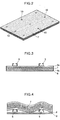
- the refractory ceiling structure according to the embodiment of the present invention illustrated in FIG. 3 and the conventional refractory ceiling structure illustrated in FIG. 4 and FIG. 5 are taken to be test samples.
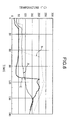
- a result of a refractory test depending on indoor side heating on the basis of BS 476 : PART 22 is shown in a graph of FIG. 6 and table 1.
- the embodiment A is compared with the comparison example B. Even though thickness of the ceiling is decreased into half under the same surface weight, it is ascertained that the embodiment A is considerably more superior than a conventional structure in connection with its heat screening property in the refractory performance. This is the reason why sharp evaporation of the water crystallization of the plaster board at the side of non heating surface is suppressed by the rock wool heat insulating material. The same effect about heating from the roof space can be found.
- preservation property of the plaster board disappears caused by heating, thus the calcium silicate plate existing at the under surface thereof can not withstand weight of two layers of the plaster boards. Subsequently, all of the calcium silicate plate and two layers of the plaster board are felled at the time of 114 minutes, and the rock wool heat insulating material is heated directly, then the flame is leaked from the joint section caused by contraction, as a result, rear surface temperature increases sharply.
- the plaster board is one layer, and the calcium silicate plate 8 is fastened at the under side of the plaster board 9b by the screws, accordingly, even though the preservation property of the plaster board 9b disappears, fall of a ceiling side panel does not occur due to the calcium silicate plate 8. Further, after evaporation of the water crystallization of the plaster board 9b, even though the rock wool heat insulating material 7 is contracted in some degree caused by heating, a flame is not leaked due to the plaster board 9a placed on the heat insulating material 7, thus a rise of a rear surface temperature is suppressed due to the water crystallization of the plaster board 9a.
- the roof-space is suit to exist only the minimum space for making construction of the cradling in comparison with the conventional refractory ceiling structure, thus, it can not only make wide of corresponding indoor space thereto, but it is not necessary to make difficult work to cover the blanket shaped heat insulating material on the cradling.
- Such a refractory ceiling structure can be obtained easily.
- the plaster board is covered on the side of the roof space of the inorganic fibriform heat insulating material, evaporation of the water crystallization of the plaster board is suppressed. The refractory property is improved in spite of the same weight.
Landscapes
- Engineering & Computer Science (AREA)
- Architecture (AREA)
- Physics & Mathematics (AREA)
- Electromagnetism (AREA)
- Civil Engineering (AREA)
- Structural Engineering (AREA)
- Building Environments (AREA)
Abstract
Description

- Heat screening property :
- average surface temperature < 140 °C + initial temperature : maximum surface temperature < 180 °C + initial temperature
- Flame screening property :
- a crevice capable of being passed by a flame during heating does not occur
- Decision :
- the heat screening property and the flame screening property are satisfied at 120 minutes
Claims (10)
- A refractory ceiling structure comprising:a first inorganic refractory board installed on a cradling;a second inorganic refractory board; andan inorganic heat insulating material arranged between the first inorganic refractory board and the second inorganic refractory board.
- A refractory ceiling structure according to claim 1, wherein said first inorganic refractory board is a plaster board.
- A heat ceiling structure according to claim 1 or claim 2, wherein said ceiling structure has a plurality of spacers which are buried in said inorganic heat insulating material.
- A refractory ceiling structure according to any one of claims 1 to 3, wherein a third inorganic refractory board is installed on said second inorganic refractory board.
- A refractory ceiling structure according to claim 4, wherein said third inorganic board is a calcium silicate plate.
- A refractory ceiling structure according to any one of claims 1 to 5, wherein said second inorganic refractory board is a plaster board.
- A refractory ceiling structure according to any one of claims 3 to 6, wherein said spacer has a column shape with diameter of from 10 to 20 mm.
- A refractory ceiling structure according to any one of claims 2 to 7, wherein the plaster board has a thickness of ≥ 9.5 mm.
- A refractory ceiling structure according to any one of claims 1 to 8, wherein the inorganic heat insulating material has a density of from 100 to 200 kg/m2 and/or a thickness of from 20 to 40 mm.
- A refractory ceiling structure according to any one of claims 5 to 9, wherein the calcium silicate plate has a thickness of ≥ 6 mm and/or a specific gravity of ≥ 0.8.
Applications Claiming Priority (2)
| Application Number | Priority Date | Filing Date | Title |
|---|---|---|---|
| JP37314899A JP2001182213A (en) | 1999-12-28 | 1999-12-28 | Fireproof ceiling structure |
| JP37314899 | 1999-12-28 |
Publications (3)
| Publication Number | Publication Date |
|---|---|
| EP1114898A2 true EP1114898A2 (en) | 2001-07-11 |
| EP1114898A3 EP1114898A3 (en) | 2001-10-17 |
| EP1114898B1 EP1114898B1 (en) | 2005-06-08 |
Family
ID=18501660
Family Applications (1)
| Application Number | Title | Priority Date | Filing Date |
|---|---|---|---|
| EP00311739A Expired - Lifetime EP1114898B1 (en) | 1999-12-28 | 2000-12-28 | Refractory ceiling structure |
Country Status (5)
| Country | Link |
|---|---|
| EP (1) | EP1114898B1 (en) |
| JP (1) | JP2001182213A (en) |
| DE (1) | DE60020665D1 (en) |
| MY (1) | MY127046A (en) |
| SG (1) | SG97173A1 (en) |
Cited By (2)
| Publication number | Priority date | Publication date | Assignee | Title |
|---|---|---|---|---|
| CN105155802A (en) * | 2015-10-09 | 2015-12-16 | 嘉兴市品鼎电器有限公司 | Composite heat insulation suspended ceiling |
| BE1026697B1 (en) * | 2019-02-13 | 2020-05-07 | Anbico Nv | Fire resistant ceiling system |
Families Citing this family (2)
| Publication number | Priority date | Publication date | Assignee | Title |
|---|---|---|---|---|
| JP2004156335A (en) * | 2002-11-07 | 2004-06-03 | Takenaka Komuten Co Ltd | Porous ceiling having smoke storage function |
| JP7210145B2 (en) * | 2018-03-05 | 2023-01-23 | 旭化成建材株式会社 | Fire-resistant structures and buildings |
Family Cites Families (5)
| Publication number | Priority date | Publication date | Assignee | Title |
|---|---|---|---|---|
| DE1982044U (en) * | 1967-11-14 | 1968-03-28 | Rigips Baustoffwerke G M B H | PERFORATED BUILDING PLATE. |
| AT348728B (en) * | 1976-10-20 | 1979-02-26 | Isovolta | MULTI-LAYER COMPOSITE PANEL |
| DE3770621D1 (en) * | 1987-03-05 | 1991-07-11 | Wolfgang Nohlen | SUSPENDED ROOM CEILING. |
| DE4036735C2 (en) * | 1989-11-18 | 1997-04-30 | Odenwald Faserplatten | Ceiling element for a fire protection false ceiling |
| DE9316000U1 (en) * | 1993-10-20 | 1994-01-05 | Gebr. Knauf Westdeutsche Gipswerke, 97346 Iphofen | Fire wall with plasterboard |
-
1999
- 1999-12-28 JP JP37314899A patent/JP2001182213A/en active Pending
-
2000
- 2000-12-12 MY MYPI20005828A patent/MY127046A/en unknown
- 2000-12-14 SG SG200007458A patent/SG97173A1/en unknown
- 2000-12-28 DE DE60020665T patent/DE60020665D1/en not_active Expired - Lifetime
- 2000-12-28 EP EP00311739A patent/EP1114898B1/en not_active Expired - Lifetime
Cited By (4)
| Publication number | Priority date | Publication date | Assignee | Title |
|---|---|---|---|---|
| CN105155802A (en) * | 2015-10-09 | 2015-12-16 | 嘉兴市品鼎电器有限公司 | Composite heat insulation suspended ceiling |
| CN105155802B (en) * | 2015-10-09 | 2017-08-29 | 嘉兴市品鼎电器有限公司 | A kind of complex heat-preservation furred ceiling |
| BE1026697B1 (en) * | 2019-02-13 | 2020-05-07 | Anbico Nv | Fire resistant ceiling system |
| EP3696339A1 (en) * | 2019-02-13 | 2020-08-19 | Anbico NV | Fire resistant system ceiling |
Also Published As
| Publication number | Publication date |
|---|---|
| EP1114898A3 (en) | 2001-10-17 |
| DE60020665D1 (en) | 2005-07-14 |
| EP1114898B1 (en) | 2005-06-08 |
| HK1037888A1 (en) | 2002-02-22 |
| MY127046A (en) | 2006-11-30 |
| SG97173A1 (en) | 2003-07-18 |
| JP2001182213A (en) | 2001-07-03 |
Similar Documents
| Publication | Publication Date | Title |
|---|---|---|
| US7823357B2 (en) | Live fire burn room and insulating system for a live fire burn room | |
| JP5038613B2 (en) | Panel connection structure | |
| JP2021516735A (en) | Back ventilation building façade and its manufacturing method | |
| EP1114898B1 (en) | Refractory ceiling structure | |
| JP3280781B2 (en) | Roof insulation structure | |
| JPH10280576A (en) | Installation structure of heat insulation and fire protection material for building exterior walls | |
| JP7064317B2 (en) | Sandwich panel mounting structure | |
| CN214786284U (en) | Steel construction assembled house periphery protects system | |
| HK1037888B (en) | Refractory ceiling structure | |
| JP7273553B2 (en) | Building panel, building panel unit, mounting structure of building panel | |
| KR102675293B1 (en) | External insulation system for buildings | |
| JPH02248565A (en) | Sound-absorbing and heat-insulating roof and ceiling structure | |
| JP2025117422A (en) | Insulation fixing device and insulation structure | |
| JP4866601B2 (en) | Double ceiling structure | |
| RU2673835C2 (en) | Distance fastening for fastening suspension of facade cover on building wall | |
| JPH1077702A (en) | Runner fixing bracket | |
| JP3559125B2 (en) | Mounting structure of runner fixing bracket | |
| JP7222746B2 (en) | Partition unit and partition structure using this partition unit | |
| RU2820736C1 (en) | Heat-insulating plate and method of its application for facade heat-insulating composite system | |
| JPH0326812Y2 (en) | ||
| JP3235392U (en) | Wall panel connecting member | |
| EP3739140B1 (en) | A fire retaining wall structure assembly for partitioning adjacent spaces | |
| JP3559124B2 (en) | Mounting structure of runner fixing bracket | |
| JP2019065681A (en) | External insulation structure and external insulation method | |
| JP2020076216A (en) | Partition wall structure and construction method of this partition wall structure |
Legal Events
| Date | Code | Title | Description |
|---|---|---|---|
| PUAI | Public reference made under article 153(3) epc to a published international application that has entered the european phase |
Free format text: ORIGINAL CODE: 0009012 |
|
| AK | Designated contracting states |
Kind code of ref document: A2 Designated state(s): AT BE CH CY DE DK ES FI FR GB GR IE IT LI LU MC NL PT SE TR Kind code of ref document: A2 Designated state(s): DE GB |
|
| AX | Request for extension of the european patent |
Free format text: AL;LT;LV;MK;RO;SI |
|
| PUAL | Search report despatched |
Free format text: ORIGINAL CODE: 0009013 |
|
| AK | Designated contracting states |
Kind code of ref document: A3 Designated state(s): AT BE CH CY DE DK ES FI FR GB GR IE IT LI LU MC NL PT SE TR |
|
| AX | Request for extension of the european patent |
Free format text: AL;LT;LV;MK;RO;SI |
|
| RIC1 | Information provided on ipc code assigned before grant |
Free format text: 7E 04B 9/04 A, 7E 04B 9/00 B |
|
| 17P | Request for examination filed |
Effective date: 20020109 |
|
| AKX | Designation fees paid |
Free format text: DE GB |
|
| 17Q | First examination report despatched |
Effective date: 20040623 |
|
| GRAP | Despatch of communication of intention to grant a patent |
Free format text: ORIGINAL CODE: EPIDOSNIGR1 |
|
| GRAS | Grant fee paid |
Free format text: ORIGINAL CODE: EPIDOSNIGR3 |
|
| GRAA | (expected) grant |
Free format text: ORIGINAL CODE: 0009210 |
|
| AK | Designated contracting states |
Kind code of ref document: B1 Designated state(s): DE GB |
|
| REG | Reference to a national code |
Ref country code: GB Ref legal event code: FG4D |
|
| REF | Corresponds to: |
Ref document number: 60020665 Country of ref document: DE Date of ref document: 20050714 Kind code of ref document: P |
|
| REG | Reference to a national code |
Ref country code: HK Ref legal event code: GR Ref document number: 1037888 Country of ref document: HK |
|
| PG25 | Lapsed in a contracting state [announced via postgrant information from national office to epo] |
Ref country code: DE Free format text: LAPSE BECAUSE OF FAILURE TO SUBMIT A TRANSLATION OF THE DESCRIPTION OR TO PAY THE FEE WITHIN THE PRESCRIBED TIME-LIMIT Effective date: 20050909 |
|
| PLBE | No opposition filed within time limit |
Free format text: ORIGINAL CODE: 0009261 |
|
| STAA | Information on the status of an ep patent application or granted ep patent |
Free format text: STATUS: NO OPPOSITION FILED WITHIN TIME LIMIT |
|
| 26N | No opposition filed |
Effective date: 20060309 |
|
| PGFP | Annual fee paid to national office [announced via postgrant information from national office to epo] |
Ref country code: GB Payment date: 20081230 Year of fee payment: 9 |
|
| GBPC | Gb: european patent ceased through non-payment of renewal fee |
Effective date: 20091228 |
|
| PG25 | Lapsed in a contracting state [announced via postgrant information from national office to epo] |
Ref country code: GB Free format text: LAPSE BECAUSE OF NON-PAYMENT OF DUE FEES Effective date: 20091228 |