TECHNICAL FIELD
The present invention relates to a carbon film, and
particularly relates to a carbon film containing, in addition
to carbon, fluorine and hydrogen, a carbon film containing,
in addition to carbon, hydrogen and nitrogen, a carbon film
containing, in addition to carbon, hydrogen and at least one
of metal, metal compound, silicon and silicon compound as
well as a method of forming the same, an object coated with a
carbon film, and a method of manufacturing the same.
BACKGROUND ART
Lubricants such as oil and wax have been
conventionally applied to surfaces of objects, which are in
slide contact with each other, such as various kinds of
machine parts and members, which are in slide contact with
each other, for ensuring good sliding property, suppressing
wearing of the objects themselves and other purposes.
However, such lubricants are soon consumed so that it is
difficult to keep it. In some cases, flowable lubricant such
as oil cannot be used even if lubricity is required.
In these days, therefore, such manners have been
proposed that a material such as fluoride such as
polytetrafluorethylene or the like, which has high lubricity
and can stably keep the lubricity for a long term, as
compared with conventional lubricating oil and others, is
applied in advance to the object surface to form a non-flowable
lubricating coating film, and that a sheet or film
made of lubricating fluoride is attached to the object
surface, e.g., by adhesion. These manners have been widely
available.
A carbon film has been known as a material, which
provide a necessary hardness to the object surface while
providing certain lubricity. The carbon films have been
utilized as coating films of machine parts for the purpose of
applying a resistance against wear.
Among carbon films, a DLC film (Diamond-Like Carbon
film) is superior in wear resistance, electrical insulation,
water repellency and others, is optically transparent, has
such a feature that a thickness thereof can be adjusted to
provide good adhesion without impairing flexibility of a
carbon-film-coated base member itself if the base member is
flexible, and can be easily formed at a relatively low
temperature by employing a plasma CVD method or the like.
Owing to these advantages, it is used as a coating film for
various kinds of objects.
However, the lubricating fluoride such as
polytetrafluorethylene does not have a sufficiently high
hardness. Accordingly, the foregoing coating film, sheet film
or the like, which can be more stable for a long term than
lubricating oil or the like, is liable to be worn, or is
liable to break and drop from the main body of the object due
to its softness.
Some objects have surfaces formed of elastic
materials, depending on their use. However, the foregoing
coating film, sheet, film or the like, which are formed on
such elastically deformable portions, are liable to be peeled
off due to elastic deformation of the objects.
Pieces of the lubricating material, which dropped from
the object, may cause unexpected situations such as an
operation failure of a machine, for example, when they bite
the sliding surfaces.
The foregoing carbon film is superior to the
lubricating fluoride in wear resistance, adhesion to the
object and others, but is sometimes required to have improved
sliding property (lubricity) with respect to another object.
The carbon film is sometimes required to have further
improved hardness for further improving the effect of
improving the surface quality of the carbon-film-coated base
member when the carbon-film-coated base member have a large
resistance against deformation so that the carbon film is not
required to follow the deformation of the base member to a
large extent, it is not necessary to give consideration to
such following property.
An object of the invention is to provide a carbon
film, which has a larger hardness and a better wear
resistance than lubricating fluoride in the prior art, and
has a better adhesion to an object than the lubricating
fluoride, as well as a method of forming the same.
Another object of the invention is to provide a carbon
film, which has a larger hardness and a better wear
resistance than lubricating fluoride in the prior art, has a
better lubricity than a conventional carbon film, and has a
better adhesion to an object than the lubricating fluoride,
as well as a method of forming the same.
Still another object of the invention is to provide a
carbon-film-coated object, which is coated with a carbon film
having a larger hardness and a better wear resistance than
lubricating fluoride in the prior art, and having a better
adhesion to the object than the lubricating fluoride, and
thereby has a good durability, as well as a method of forming
the same.
Yet another object of the invention is to provide a
carbon-film-coated object, which is coated with a carbon film
having a larger hardness and a better wear resistance than
lubricating fluoride in the prior art, having a better
lubricity than a conventional carbon film and having a better
adhesion to the object than the lubricating fluoride, and
thereby has a good durability, as well as a method of forming
the same.
DISCLOSURE OF THE INVENTION
The invention provides a carbon film and a carbon-film-coated
object as well as a carbon film forming method
and a method of manufacturing a carbon-film-coated object,
which are described below.
BRIEF DESCRIPTION OF THE DRAWINGS
Fig. 1 shows a schematic structure of an example of a
film forming device which can be utilized for manufacturing a
carbon film and a carbon-film-coated object according to the
invention;
Fig. 2 shows a schematic structure of another example
of the film forming device which can be utilized for
manufacturing the carbon film and the carbon-film-coated
object according to the invention;
Fig. 3 shows a schematic structure of still another
example of the film forming device which can be utilized for
manufacturing the carbon film and the carbon-film-coated
object according to the invention;
Fig. 4 is a cross section of an example of the carbon-film-coated
object according to the invention;
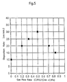
Fig. 5 shows a relationship between a supply flow rate
of a hydrocarbon compound gas and a carbon fluoride compound
gas forming a deposition gas and a deposition rate;
Fig. 6 shows a supply flow rate of a hydrocarbon
compound gas and a carbon fluoride compound gas forming a
deposition gas and spectra, determined by FT-IR spectrum
analysis, of the carbon films formed with the supply flow
rate;
Fig. 7 shows a supply flow rate of a hydrocarbon
compound gas and a carbon fluoride compound gas forming a
deposition gas and spectra, determined by XPS, of the carbon
films formed with the supply flow rate;
Fig. 8 shows a relationship between a ratio (IR·C-F)/(IR·C-H)
of peak areas of spectrum determined by FT-IR
spectrum analysis and (F1S/C1S) determined by XPS in the
carbon film;
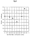
Fig. 9 shows a relationship between a supply flow rate
of a hydrocarbon compound gas and a carbon fluoride compound
gas forming a deposition gas and a friction coefficient of
the carbon film;
Fig. 10 shows a relationship between a supply flow
rate of a hydrocarbon compound gas and a carbon fluoride
compound gas forming a deposition gas and a hardness
(Vickers' hardness) of the carbon film;
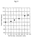
Fig. 11 shows a relationship between a supply flow
rate of a hydrocarbon compound gas and a carbon fluoride
compound gas forming a deposition gas and water repellency
(repellency angle and contact angle) of the carbon film;
Fig. 12 shows a relationship between a modulation
frequency of a high-frequency power for gas plasma formation
and (F1S/C1S), determined by XPS, of the carbon film formed
under the modulation frequency;
Fig. 13 shows a relationship between a duty of
frequency modulation of the high-frequency power for gas
plasma formation and (F1S/C1S), determined by XPS, and water
repellency of the carbon film formed under the modulation
frequency; and
Fig. 14(A) shows a schematic structure of another
example of the film forming device which can be utilized for
manufacturing the carbon film and the carbon-film-coated
object according to the invention, and Fig. 14(B) shows
another example of an electrode for applying a plasma
formation power in the device shown in Fig. 14(A).
PREFERRED EMBODIMENTS FOR IMPLEMENTING THE INVENTION
The carbon film and the method of manufacturing the
same as well as the carbon-film-coated object and the method
of manufacturing the same according to the invention will now
be described in greater detail.
First, description will now be given on a carbon film
containing fluorine and hydrogen as well as matters relating
to it.
Each of the carbon film described in the foregoing
item (1) in [1], the carbon film in the carbon-film-coated
object described in the foregoing item (1) in [2], the carbon
film obtained by the carbon film forming method described in
the foregoing item (1) in [3] and the carbon film formed on
the object by the carbon-film-coated object manufacturing
method described in the foregoing item (1) in [4] (each of
which may be referred to as a "fluorine/hydrogen-containing
carbon film" hereinafter), has a C-F bond portion, may be
considered as a carbon film in which fluoride is mixed, and
has good lubricity, good hardness and good wear resistance as
a whole owing to existence of the carbon film portion having
certain lubricity and harder than fluoride and the C-F bond
portion having higher lubricity than the carbon film portion.
Further, each film has a good hardness and a good wear
resistance, and therefore peeling from the object, which may
be caused due to softness, is suppressed so that the film can
be formed on the base member or the film formation target
object with good adhesion. The carbon-film-coated object in
the item (1) of [2], which is coated with the carbon film
containing fluorine and hydrogen, has good durability.
The fluorine/hydrogen-containing carbon film according
to the invention requires existence of C-F bonds, but the C-F
bonds which are excessively large in number reduce the
hardness and the wear resistance so that the carbon film is
configured to have a spectrum, determined by FT-IR (Fourier
Transform Infrared) spectrum analysis, exhibiting such a
relationship that a ratio (IR·C-F)/(IR·C-H) between a peak
area (IR·C-F) in a range from 1000 cm-1 - 1300 cm-1 resulting
from C-F bonds and a peak area (IR·C-H) in a range from 2800
cm-1 to 3100 cm-1 resulting from C-H bonds is larger than 0,
and a spectrum, determined by XPS (X-ray photoelectron
spectrum analysis), exhibiting such a relationship that a
ratio (F1S/C1S) between a peak intensity resulting from F1S and
a peak intensity resulting from C1S is larger than 0 and
smaller than 3, as already described.
The fluorine/hydrogen-containing carbon film according
to the invention may further contain nitrogen for further
increasing the hardness. Alternatively, it may contain at
least one of metal, metal compound (typically, metal oxide,
metal nitride or metal carbide), silicon and silicon compound
(typically, silicon oxide, silicon nitride or silicon
carbide).
For improving adhesion to the object and achieving the
intended hardness and wear resistance as well as the intended
lubricity, a rate of the C-F bonds may increase or decrease
continuously or stepwise in the direction of the thickness of
the film. In this case, the carbon film may be configured
such that the rate of the C-F bonds increases continuously or
stepwise as the position moves in the direction of the
thickness of the film from the side near the carbon-film-coated
base member or the object body to the side remote
therefrom.
The fluorine/hydrogen-containing carbon film according
to the invention is required to have a predetermined
hardness, and may be typically a DLC (diamond-like carbon)
film.
The DLC film is superior in sliding property
(lubricity) with respect to another object, wear resistance,
electrical insulation, water repellency and others, and is
light-transparent if it has an ordinary thickness. By
adjusting the thickness, the film can be formed with good
adhesion without impairing the flexibility of the base member
or the object even if the base member or the object to be
coated with the carbon film has a surface formed of a
flexible material such as rubber or resin. By the plasma CVD
method or the like, it can be formed easily at a relatively
low temperature.
The method of manufacturing the carbon film described
in the item (1) in [1] and the carbon film of the carbon-film-coated
object described in the item (1) in [2] may be a
plasma CVD method, a sputtering method, an ion plating method
or the like, and particularly the plasma CVD method can
provide such an advantage that the same device can be used
for pretreatment with plasma to be described later and
formation of the carbon film. The film forming method such as
plasma CVD, sputtering, ion plating or the like can provide
such an advantage that the film formation can be performed at
a temperature range not thermally damaging the surface
material of the carbon film formation base member or the film
formation target object even when it is made of a material
such as rubber or resin having a relatively low heat
resistance.
For forming the carbon film by the plasma CVD method,
the deposition pressure is set, e.g., to about 100 mTorr, and
the deposition temperature is set to 100°C or less, although
not restricted to these values, whereby a DLC film can be
formed. The higher deposition temperature increases the
hardness of the film, and the temperature of 500°C or more
provides the carbon film having extremely good wear
resistance. The temperature of 900°C or more provides a
diamond film.
As a typical example of the method of forming the
fluorine/hydrogen-containing carbon film, the carbon film
forming method described in the item (1) in [3] may be
employed, and the method described in the item (1) in [4]
utilizing the method described in the item (1) in [3] may be
employed as a typical example of the method of manufacturing
the carbon-film-coated object.
The hydrocarbon compound gas, which can be employed
for forming the carbon film in these methods, may be a gas of
a material such as methane (CH4), ethane (C2H6), propane
(C3H8), butane (C4H10), acetylene (C2H2), benzene (C6H6) or
cyclohexane (C6H12), which is generally used for carbon film
formation, and the material gas may be a mixture of the above
hydrocarbon compound gas and a carrier gas such as a hydrogen
gas, an inert gas or the like, If necessary.
The carbon fluoride compound gas may be a
tetrafluoromethane (CF4) gas, a hexafluoroethane (C2F6) gas, a
octafluorocyclobutane (C4F8) gas or the like. For forming the
carbon film, the mixture of the hydrocarbon compound gas and
the carbon fluoride compound gas may be used, whereby the
lubricity of the carbon film can be improved, and further the
deposition rate can be improved. Thereby, the productivity of
the film can be improved. Further, film adhesion can be
improved owing to reduction in film stress, and gas barrier
property can be improved.
For formation of the fluorine/hydrogen-containing
carbon film according to the invention, the hydrocarbon
compound gas and the carbon fluoride compound gas as well as
a nitrogen containing gas (N2, ammonia, hydrazine or the
like) may be used as the deposition material gas, whereby the
fluorine/hydrogen-containing carbon film containing the
nitrogen, as described above and having an improved hardness
may be formed. Further, the hydrocarbon compound gas and the
carbon fluoride compound gas as well as the gas forming at
least one of metal, metal compound (typically, metal oxide,
metal nitride or metal carbide), silicon and silicon compound
(typically, silicon oxide, silicon nitride or silicon
carbide) may be used as the deposition material gas for
forming the fluorine/hydrogen-containing carbon film
containing at least one of metal, metal compound (typically,
metal oxide, metal nitride or metal carbide), silicon and
silicon compound (typically, silicon oxide, silicon nitride
or silicon carbide) as described above.
For mixing the oxide, nitride or carbide of silicon
(Si) or metal in the film, Si-containing compound (SiH4, TEOS
or the like), Ti compound (TiCl4, tetraethoxytitanium
(Ti(OC2H5)4), tetraisopropoxytitanium (Ti(O-i-C3H7)4) or the like)
may be reacted with oxygen or the like.
Alternatively, the carbon film may be doped with
sputter particles produced by sputtering of a sputter target,
which are made of metal, metal compound (typically, metal
oxide, metal nitride or metal carbide), silicon or silicon
compound (typically, silicon oxide, silicon nitride or
silicon carbide), for forming the fluorine/hydrogen-containing
carbon film containing at least one of metal,
metal compound (typically, metal oxide, metal nitride or
metal carbide), silicon and silicon compound (typically,
silicon oxide, silicon nitride or silicon carbide).
For further increasing the adhesion to the base member
or the object, and satisfying both the hardness and the wear
resistance as well as the lubricity in any one of the
foregoing structures and methods, the mixing rate of the
hydrocarbon compound gas and the carbon fluoride compound gas
may be changed with time in the supply of the gases to form
the carbon film configured such that the rate of the C-F
bonds may increase continuously or stepwise as the position
moves in the direction of the thickness of the film from the
side near the carbon-film-coated base member or the object to
the side remote therefrom.
For forming the fluorine/hydrogen-containing carbon
film by the plasma CVD method, various devices such as a
parallel-plate type plasma CVD device may be employed, and
the following manner may be employed for forming the
fluorine/hydrogen-containing carbon film. A deposition
chamber formed of a plasma producing chamber and a plasma
processing chamber connected thereto is employed as the
foregoing deposition chamber, the carbon film formation base
member or the film formation target object is located in the
plasma processing chamber, a part of the deposition material
gas is supplied into the plasma processing chamber, and the
other is supplied into the plasma producing chamber. In
addition to the above:
the fluorine/hydrogen-containing carbon film is formed
on the base member or the object.
As more specific examples, the hydrocarbon compound
gas and the carbon fluoride compound gas as well as the gas
forming at least one of metal, metal compound (typically,
metal oxide, metal nitride or metal carbide), silicon and
silicon compound (typically, silicon oxide, silicon nitride
or silicon carbide) are used as the deposition material gas,
the gas forming at least one of metal, metal compound
(typically, metal oxide, metal nitride or metal carbide),
silicon and silicon compound (typically, silicon oxide,
silicon nitride or silicon carbide) is supplied into the
plasma producing chamber, and the hydrocarbon compound gas
and the carbon fluoride compound gas are supplied into the
plasma processing chamber; and
whereby
the fluorine/hydrogen-containing carbon film
containing at least one of metal, metal compound (typically,
metal oxide, metal nitride or metal carbide), silicon and
silicon compound (typically, silicon oxide, silicon nitride
or silicon carbide) is formed on the base member or the
object.
In the invention, the deposition chamber formed of the
plasma producing chamber and the plasma processing chamber
connected thereto may be employed, and the plasma may be
formed from the gas(es) in each of the plasma producing
chamber and the plasma processing chamber by application of
the electric power, in which case such an advantage can be
achieved that the formation of the gas plasma in each of the
plasma producing chamber and the plasma processing chamber
can be controlled.
The following carbon film forming method may be
employed. The deposition chamber formed of the plasma
producing chamber and the plasma processing chamber connected
thereto are employed, the carbon film formation base member
or the film formation target object is located in the plasma
processing chamber, a sputter target made of at least one of
metal, metal compound (typically, metal oxide, metal nitride
or metal carbide), silicon and silicon compound (typically,
silicon oxide, silicon nitride or silicon carbide) is located
in the plasma producing chamber, the hydrocarbon compound gas
and the carbon fluoride compound gas are supplied into the
plasma processing chamber, a gas for sputtering is supplied
into the plasma producing chamber, and an electric power is
applied to the gas for sputtering to form plasma therefrom;
and
the carbon film containing at least one of metal,
metal compound, silicon and silicon compound is formed on the
base member or the film formation target object.
In this case, an inert gas (e.g., argon gas) may be
employed as the gas for sputtering.
Description will now be given on the carbon film
containing hydrogen and nitrogen and matters relating to it
as well as the carbon film containing hydrogen and at least
one of metal, metal compound, silicon and silicon compound
and matters relating to it.
Each of the carbon film described in the foregoing
item (2) in [1], the carbon film in the carbon-film-coated
object described in the foregoing item (2) in [2], the carbon
film obtained by the carbon film forming method described in
the foregoing item (2) in [3] and the carbon film formed on
the object by the carbon-film-coated object manufacturing
method described in the foregoing item (2) in [4], (each of
which may be referred to as a "hydrogen/nitrogen-containing
carbon film" hereinafter), has a C-N bond portion. Therefore,
it has a good lubricity resulting from the carbon film
portion, and has a hardness and a good wear resistance as a
whole owing to existence of the carbon film portion harder
than fluoride and the nitride portion having a further large
hardness. Since each film has a good hardness and a good wear
resistance, peeling from the object is suppressed so that the
film can be formed on the base member or the target object
with good adhesion. The carbon-film-coated object in the item
(2) of [2], which is coated with such a carbon film
containing hydrogen and nitrogen, has good durability.
For further increasing the hardness, the
hydrogen/nitrogen-containing carbon film according to the
invention may contain at least one of metal, metal compound
(typically, metal oxide, metal nitride or metal carbide),
silicon and silicon compound (typically, silicon oxide,
silicon nitride or silicon carbide).
Each of the carbon film described in the foregoing
item (3) in [1], the carbon film in the carbon-film-coated
object described in the foregoing item (3) in [2], the carbon
films obtained by the carbon film forming methods described
in the foregoing items (3) and (4) in [3] and the carbon
films formed on the objects by the carbon-film-coated object
manufacturing methods described in the foregoing items (3)
and (4) in [4], (each of which may be referred to as a
"hydrogen/metal/etc-containing carbon film" hereinafter), has
a good lubricity owing to existence of the carbon film
portion, has a hardness and a good wear resistance as a whole
owing to existence of the hard carbon film portion and at
least one of metal, metal compound (typically, metal oxide,
metal nitride or metal carbide), silicon and silicon compound
(typically, silicon oxide, silicon nitride or silicon
carbide). Since each film has a good hardness and a good wear
resistance, peeling from the object is suppressed so that the
film can be formed on the base member or the film formation
target object with good adhesion. The carbon-film-coated
object in the item (3) of [2], which is coated with the
hydrogen/metal/etc-containing carbon film, has good
durability.
The hydrogen/nitrogen-containing carbon film and the
hydrogen/metal/etc-containing carbon film according to the
invention are required to have a predetermined hardness, and
may be typically a DLC (diamond-like carbon) film.
The DLC film has features already described in
connection with the fluorine/hydrogen-containing carbon film.
The method of forming the hydrogen/nitrogen-containing
carbon film and the hydrogen/metal/etc-containing carbon film
as well as the carbon films of the carbon-film-coated
objects, which are coated with these films, respectively, may
be the plasma CVD method, sputtering method, ion plating
method or the like, similarly to the cases for forming the
fluorine/hydrogen-containing carbon film. These film forming
methods can achieve the advantages already described.
As a typical example of the formation of the
hydrogen/nitrogen-containing carbon film, the carbon film
forming method described in the item (2) of [3] may be
employed, and the method described in the item (2) of [4]
utilizing the method described in the item (2) of [3] may be
employed as the typical example of the method of
manufacturing the carbon-film-coated object.
As a typical example of the formation of the
hydrogen/metal/etc-containing carbon film, the carbon film
forming methods described in the items (3) and (4) of [3] may
be employed, and the methods described in the items (3) and
(4) of [4] utilizing the methods described in the items (3)
and (4) of [3] may be employed as the typical examples of the
method of manufacturing the carbon-film-coated object.
The hydrocarbon compound gas, which can be employed
for forming the carbon film in these methods, may be similar
to those, which can be employed for formation of the
fluorine/hydrogen-containing carbon film. If necessary, a
mixture of the above hydrocarbon compound gas and a carrier
gas such as a hydrogen gas, an inert gas or the like may be
employed.
As the nitrogen containing gas, a gas of nitrogen (N2),
ammonia, hydrazine or the like may be used.
For formation of the hydrogen/nitrogen-containing
carbon film, the hydrocarbon compound gas and the nitrogen
containing gas as well as the gas forming at least one of
metal, metal compound (typically, metal oxide, metal nitride
or metal carbide), silicon and silicon compound (typically,
silicon oxide, silicon nitride or silicon carbide) may be
used as the deposition material gas for forming the
hydrogen/nitrogen-containing carbon film containing at least
one of metal, metal compound (typically, metal oxide, metal
nitride or metal carbide), silicon and silicon compound
(typically, silicon oxide, silicon nitride or silicon
carbide).
In either of the cases of forming the
hydrogen/nitrogen-containing carbon film as well as the
hydrogen/metal/etc-containing carbon film, and particularly
in the case of mixing the oxide, nitride or carbide of
silicon (Si) or metal in the film, Si-containing compound
(SiH4, TEOS or the like), Ti compound (TiCl4,
tetraethoxytitanium (Ti(OC2H5)4), tetraisopropoxytitanium
(Ti(O-i-C3H7)4)or the like) may be reacted with oxygen or the like.
Alternatively, the carbon film may be doped with
sputter particles produced by sputtering of a sputter target,
which are made of metal, metal compound (typically, metal
oxide, metal nitride or metal carbide), silicon or silicon
compound (typically, silicon oxide, silicon nitride or
silicon carbide), for forming the hydrogen/nitrogen-containing
carbon film or the hydrogen/metal/etc-containing
carbon film containing at least one of metal, metal compound
(typically, metal oxide, metal nitride or metal carbide),
silicon and silicon compound (typically, silicon oxide,
silicon nitride or silicon carbide).
For forming the hydrogen/nitrogen-containing carbon
film or the hydrogen/metal/etc-containing carbon film by the
plasma CVD method, various devices such as a parallel-plate
type plasma CVD device may be employed, and the following
manner may be employed.
A deposition chamber formed of a plasma producing
chamber and a plasma processing chamber connected thereto is
employed as the foregoing deposition chamber, the carbon film
formation base member or the film formation target object is
located in the plasma processing chamber, a part of the
deposition material gas is supplied into the plasma
processing chamber, and the other is supplied into the plasma
producing chamber. In addition to the above:
the hydrogen/nitrogen-containing carbon film or the
hydrogen/metal/etc-containing carbon film is formed on the
base member or the object.
As more specific examples of the above case for
forming the hydrogen/nitrogen-containing carbon film, the
hydrocarbon compound gas is supplied into the plasma
processing chamber, and the nitrogen containing gas is
supplied into the plasma producing chamber; and
the carbon film containing the hydrogen and nitrogen
is formed on the base member or the object.
As another example of formation of the
hydrogen/nitrogen-containing carbon film, the hydrocarbon
compound gas and the nitrogen containing gas as well as the
gas forming at least one of metal, metal compound (typically,
metal oxide, metal nitride or metal carbide), silicon and
silicon compound (typically, silicon oxide, silicon nitride
or silicon carbide) may be used as the deposition material
gas, the gas forming at least one of metal, metal compound,
silicon and silicon compound is supplied into the plasma
producing chamber, and the hydrocarbon compound gas and the
nitrogen containing gas are supplied into the plasma
processing chamber; and
the hydrogen/nitrogen-containing carbon film
containing at least one of metal, metal compound, silicon and
silicon compound is formed on the base member or the object.
The following carbon film forming method may also be
employed. A deposition chamber formed of a plasma producing
chamber and a plasma processing chamber connected thereto is
employed as the foregoing deposition chamber, the carbon film
formation base member or the film formation target object is
located in the plasma processing chamber, and a sputter
target made of at least one of metal, metal compound
(typically, metal oxide, metal nitride or metal carbide),
silicon and silicon compound (typically, silicon oxide,
silicon nitride or silicon carbide) is located in the plasma
producing chamber, and the hydrocarbon compound gas and the
nitrogen containing gas are supplied into the plasma
processing chamber; and
the carbon film containing at least one of metal,
metal compound, silicon and silicon compound is formed on the
base member or the film formation target object.
In this case, an inert gas (e.g., argon gas) may be
employed as the gas for sputtering.
As an example of formation of the hydrogen/metal/etc-containing
carbon film, a deposition chamber formed of a
plasma producing chamber and a plasma processing chamber
connected thereto is employed as the foregoing deposition
chamber, the carbon film formation base member or the film
formation target object is located in the plasma processing
chamber, the gas forming at least one of metal, metal
compound, silicon and silicon compound is supplied into the
plasma producing chamber, and the hydrocarbon compound gas is
supplied into the plasma processing chamber; and
the carbon film containing at least one of metal,
metal compound, silicon and silicon compound is formed on the
base member or the object.
Each of the foregoing fluorine/hydrogen-containing
carbon film, hydrogen/nitrogen-containing carbon film and
hydrogen/metal/etc-containing carbon film contains hydrogen
to improve the slidability thereof.
In any one of the foregoing fluorine/hydrogen-containing
carbon film, hydrogen/nitrogen-containing carbon
film and hydrogen/metal/etc-containing carbon film, either of
a DC power and a high-frequency power can be used as the
electric power for plasma formation. When using the high-frequency
power, such a high-frequency power may be employed
that is prepared by effecting amplitude modulation at a
predetermined modulation frequency on a basic high-frequency
power of a predetermined frequency. In this case, the basic
high-frequency power of the predetermined frequency (e.g., of
13.56 MHz) is subjected to the amplitude modulation at the
modulation frequency of 1/100000 - 1/10 of the predetermined
frequency of the basic power.
By using such a modulated high-frequency power as the
power for forming the plasma from the deposition material
gas, the produced plasma can have a high density, and thereby
a rate of reaction is improved so that deposition can be
performed at a low temperature. By effecting the modulation
as described above, the reaction is promoted on the outer
surface of the film formation base member or the film
formation target object so that the film adhesion can be
improved, and the deposition rate can be improved. Thereby,
the productivity of the film can be improved.
The basic high-frequency power before the modulation
may have a waveform such as a sinusoidal, square, sawtooth-like
or triangular form. The amplitude modulation may be
pulse modulation conducted by on/off of the power supply, or
may be another modulation in the form of pulse.
The basic high-frequency power has a frequency of
13.56 MHz or more, although not restricted thereto. The
frequency lower than the above tends to cause an insufficient
plasma density. The frequency of the basic high-frequency may
be, e.g., about 500 MHz or less in view of a cost of the
high-frequency power source and others.
The modulation frequency may be in the foregoing range
because a modulation frequency smaller than 1/100000 of the
frequency of the basic high-frequency power significantly
lowers the deposition rate. The modulation frequency larger
than 1/10 makes the matching difficult, and lowers the
uniformity in film thickness.
In any one of the foregoing cases, the duty ratio
((on-time)/(on-time + off-time)) of the modulation may be in
a range from about 5% to about 90%. The duty ratio lower than
5% would lower the deposition rate. The duty ratio larger
than 90% would excessively increase the power supply time,
and therefore would reduce the effect of improving the plasma
density which could be achieved by the modulated high-frequency
power.
For any one of the foregoing fluorine/hydrogen-containing
carbon film, the hydrogen/nitrogen-containing
carbon film and the hydrogen/metal/etc-containing carbon
film, such a pretreatment may be performed prior to the
carbon film formation that the film formation surface of the
base member or the film formation target object is exposed to
plasma of at least one of fluorine containing gas, hydrogen
gas and oxygen gas.
The above fluorine-containing gas may be a fluorine
(F2) gas, a nitrogen trifluoride (NF3) gas, a sulfur
hexafluoride (SF6) gas, a tetrafluoromethane (CF4) gas, a
hexafluoroethane (C2F6) gas, a octafluorocyclobutane (C4F8)
gas, a silicon tetrafluoride (SiF4) gas, a disilicon
hexafluoride (Si2F6) gas, a chlorine trifluoride (ClF3) gas, a
hydrogen fluoride (HF) gas or the like.
By exposing the film formation surface of the film
formation base member or the film formation target object to
the plasma of the pretreatment gas, the film formation
surface is cleaned, and the surface roughness of the film
formation surface is improved. These contribute to
improvement of the adhesion of the carbon film so that the
carbon film having high adhesion can be obtained.
If the fluorine containing gas plasma is employed for
the film formation surface of the film formation base member
or the film formation target object, which is made of an
organic material such as rubber or resin, the plasma can
conduct a termination treatment on the film formation surface
with the fluorine. If the hydrogen gas plasma is employed for
the same, the plasma can conduct a termination treatment on
the film formation surface with the hydrogen. Since the
fluorine-carbon bond and the hydrogen-carbon bond are stable,
the carbon atoms in the film form stable bonds with the
fluorine atoms or hydrogen atoms at the surface portion of
the base member or the film formation target object when the
carbon film is formed on the surface subjected to such
termination treatment. This improves the adhesion of the
carbon film, which will be formed later, to the base member
or the like.
When employing the oxygen gas plasma, smear due to,
e.g., organic matters adhering to the film formation surface
can be removed particularly effectively so that the adhesion
of the carbon film to be formed subsequently can be improved.
In the method according to the invention, the
pretreatment using plasma may be performed several times with
the same kind of plasma or with different kinds of plasma.
For example, if the film formation surface is exposed to the
fluorine-containing gas plasma or hydrogen gas plasma after
exposing the film formation surface to the oxygen gas plasma,
and the carbon film is subsequently deposited thereon, the
fluorine or hydrogen termination is performed at the surface
after the surface is cleaned so that the carbon film
deposited thereafter has a very good adhesion to the film
formation surface.
In the carbon film coated object and the object (film
formation target object) in the manufacturing method thereof
according to the invention, at least the surface coated with
the carbon film may be made of rubber and/or resin, and at
least the surface coated with the carbon film may be made of
metal and/or ceramics (ceramic material).
The rubber may be, e. g., natural rubber, butyl
rubber, ethylene-propylene rubber, chloroprene rubber,
chlorinated polyethylene rubber, epichlorohydrin rubber,
acrylic rubber, nitrile rubber, urethane rubber, silicone
rubber, fluororubber or the like.
The resin may be either a thermosetting resin or
thermoplastic resin.
The thermosetting resin may be, e.g., phenolformaldehyde
resin, urea resin, melamine-formaldehyde resin,
epoxy resin, furan resin, xylene resin, unsaturated polyester
resin, silicone resin, diallyl phthalate resin or the like.
The thermoplastic resin may be, e. g., vinyl resin
(polyvinyl chloride, polyvinyl butyrate, polyvinyl alcohol,
polyvinyl acetate, polyvinyl formal, polyvinyl dichloride or
the like), polyvinylidene chloride, chlorinated polyether,
polyester resin (polystyrene, styrene-acrylonitrile copolymer
or the like), ABS, polyethylene, polypropylene, polyacetal,
acrylic resin [poly(methyl methacrylate), modified acrylic
resin or the like], polyamide resin (nylon 6, 66, 610, 11 or
the like), cellulose resin (ethyl cellulose, acetyl
cellulose, propyl cellulose, cellulose acetate butyrate,
cellulose nitrate or the like), polycarbonate, phenoxy resin,
fluorine-containing resin (resin formed of chlorotrifluoro
ethylene, ethylene tetrafluoride, ethylene tetrafluoride
propylene hexafluoride, vinylidene fluoride or the like), or
polyurethane or the like.
The metal may be, e. g., stainless steel, hard metal
carbide such as WC, high-speed steel, aluminum, aluminum
alloy or the like, and the ceramics (ceramic material) may be
alumina, silicon nitride, aluminum nitride or the like.
The object in the carbon-film-coated object according
to the invention is not particularly restricted, provided
that the carbon film according to the invention can be
formed. Various objects including objects exemplified below
can be the targets for the carbon film formation according to
the invention.
Various objects made of metal or ceramics such as
machine tool parts, dies, jigs, parts (e.g., gears, slide
parts and others) of vehicles, aircraft and ships, parts
(e.g., wafer carrier transporting arms, various rails) of ion
implanting devices, deposition devices, etching devices or
the like for semiconductor device manufacturing, kitchen
appliances (pans and others), kitchen goods (pans, frying
pans and others), bath facilities and goods (hot water tap
parts and others), sanitary facilities and goods, containers
and other.
Various objects made of rubber such as machine tool
parts, parts of vehicles, aircraft, ships and others (e.g.,
vibration damper rubber parts used in drives including
engines, stirring portions, exhaust portions, body
connections, suspensions as well as rubber hoses used in fuel
systems, air systems, lubricating oil systems, brake systems,
air-conditioning systems, cooling water systems and others;
wipers, various sealing parts, various liquid-tight caps and
others of automobiles)
Various objects made of resin such as machine tool
parts (e.g., gears, slide parts and others), jigs, electric
parts (insulators, terminals and others), parts of vehicles,
aircraft and ships (e.g., fuel tanks, bodies and others of
automobiles), kitchen appliances, kitchen goods, bath
facilities and goods, sanitary facilities and goods, films,
sheets, recording disks, nets for fishery and others,
clothing parts such as buttons, toys and their parts,
ornaments, stationeries and their parts, sport goods and
their parts, and household goods and their parts (containers
such as casing, their parts, and tableware).
Embodiments of the invention will now be described
with reference to the drawings.
Fig. 1 shows a schematic structure of an example of a
film forming device which can be used for manufacturing a
carbon film and a carbon-film-coated object according to the
invention.
The device in Fig. 1 is a plasma CVD device, which
includes a vacuum chamber 1 (an example of a deposition
chamber) connected to a vacuum pump 12 via a pressure control
value 11, and also includes electrodes 2 and 3, which are
opposed to each other, and are arranged in the vacuum chamber
1. The electrode 3 is grounded, and the electrode 2 is
connected to a high-frequency or radio-frequency power source
23 via a matching box 22. A heater 21 for heating a film
formation target object S, which is held on the electrode 2,
is arranged on the electrode 2. A gas supply portion 4 is
connected to the chamber 1 for supplying a film formation or
deposition material gas into the chamber 1. The gas supply
portion 4 includes one or more gas sources 431, 432, ··· for
the deposition material gas connected to the chamber 1 via
mass- flow controllers 411, 412, ··· and valves 421, 422, ···.
Description will now be given on a method of
manufacturing the carbon-film-coated object according to the
invention by the above device.
First, a deposition or film formation target object S
of a predetermined material (a rubber plate for a vibration
damper in this example) is placed on the high-frequency
electrode 2 in the chamber 1 with its film formation surface
opposed to the electrode 3, and the exhaust pump 12 operates
to reduce the inner pressure of the chamber 1 to a
predetermined value. The gas supply portion 4 supplies a
pretreatment gas formed of at least one of a fluorine
containing gas, a hydrogen containing gas and an oxygen
containing gas into the chamber 1, and the high-frequency
power source 23 supplies a high-frequency power to the
electrode 2 via the matching box 22 so that plasma is formed
from the pretreatment gas thus supplied, and a pretreatment
is effected on the film formation surface S1 of the object S
in the plasma. This surface treatment (pretreatment) is
desired, but is not essential.
Therefore, if necessary, the gas is discharged from
the chamber 1 for further control of the pressure, and the
gas supply portion 4 supplies the deposition material gas
into the chamber 1.
The deposition material gas thus supplied includes a
hydrocarbon compound gas and a carbon fluoride compound gas
when a fluorine/hydrogen-containing carbon film is to be
formed. When a hydrogen/nitrogen-containing carbon film is to
be formed, it contains a hydrocarbon compound gas and a
nitrogen containing gas. When a hydrogen/metal/etc-containing
carbon film is to be formed, it contains hydrocarbon compound
gas and a gas forming at least one of metal, metal compound,
silicon and silicon compound.
The high-frequency power source 23 supplies a high-frequency
power to the electrode 2 via the matching box 22 so
that plasma is formed from the gas thus supplied, and a
carbon film 5 is formed on the film formation surface S1 of
the object S. The carbon film 5 on the carbon-film-coated
object S (see Fig. 4) obtained in this manner is the
fluorine/hydrogen-containing carbon film, when the
hydrocarbon compound gas and the carbon fluoride compound gas
are used as the deposition gas. The carbon film 5 is the
hydrogen/nitrogen-containing carbon film, when the
hydrocarbon compound gas and the nitrogen containing gas are
used as the deposition gas. The carbon film 5 is the
hydrogen/metal/etc-containing carbon film, when the
hydrocarbon compound gas and the gas containing at least one
of the metal, metal compound, silicon and silicon compound
are used.
Further description will be given on the case of
forming the fluorine/hydrogen-containing carbon film. For
supplying the hydrocarbon compound gas and the carbon
fluoride compound gas into the vacuum chamber 1 for forming
the carbon film, a mixing ratio (a ratio between supply flow
amounts or rates) of these gases is controlled to provide the
carbon film 5 (DLC film in this embodiment), in which a
spectrum, determined by FT-IR (Fourier Transform Infrared)
spectrum analysis, exhibits such a relationship that a ratio
(IR·C-F)/(IR·C-H) between a peak area (IR·C-F) in a range
from 1000 cm-1 - 1300 cm-1 resulting from C-F bonds and a peak
area (IR·C-H) in a range from 2800 cm-1 to 3100 cm-1 resulting
from C-H bonds is larger than 0, and a spectrum, determined
by XPS (X-ray photoelectron spectrum analysis), exhibits such
a relationship that a ratio (F1S/C1S) between a peak intensity
resulting from F1S and a peak intensity resulting from C1S is
larger than 0 and smaller than 3.
This carbon film has the characteristics of the DLC
film already described, has good adhesion to the object S,
sufficient hardness and good wear resistance, and also has
good sliding and lubricating properties with respect to
another object owing to provision of the C-F bond portion.
Further description will be given on the case of
forming the hydrogen/nitrogen-containing carbon film. For
supplying the hydrocarbon compound gas and the nitrogen
containing gas into the vacuum chamber 1 for forming the
carbon film, a mixing ratio (a ratio between supply flow
amounts or rates) of these gases is controlled to provide the
carbon film (DLC film in this embodiment), in which an amount
of the C-N bond portion is controlled.
This carbon film has the characteristics of the DLC
film already described, has good adhesion to the object S, a
sufficient hardness and good wear resistance, and also has
good lubricity owing to a DLC film portion as well as high
hardness owing to provision of the DLC film portion and the
C-N bond portion.
Further description will be given on the case of
forming the hydrogen/metal/etc-containing carbon film. For
supplying the hydrocarbon compound gas and the gas containing
at least one of the metal, metal compound, silicon and
silicon compound into the vacuum chamber 1 for forming the
carbon film, a mixing ratio (a ratio between supply flow
amounts or rates) of these gases is controlled to provide the
carbon film (DLC film in this embodiment), in which the
foregoing metal or the like is dispersed.
This carbon film has the characteristics of the DLC
film already described, has good adhesion to the object S, a
sufficient hardness and good wear resistance, and also has
good lubricity owing to a DLC film portion as well as high
hardness owing to provision of the DLC film portion and the
metal portion or the like.
Referring to Fig. 2, description will now be given on
another example of the film forming device, which can be used
for forming the carbon film and manufacturing the carbon-film-coated
object according to the invention.
A film forming device shown in Fig. 2 is also a plasma
CVD device. This device is the same as the device shown in
Fig. 1 except for that an arbitrary waveform generating
device 24 is connected to the high-frequency power source 23,
and the same parts as those in the device shown in Fig. 1
bear the same reference numbers.
For forming the film on the outer surface of the film
formation target object S by this device, a pulse-modulated
high-frequency power, which is prepared by the high-frequency
power source 23 and the arbitrary waveform generating device
24, is supplied to the inner electrode 2 via the matching box
22 so that plasma is formed from the deposition material gas.
The pulse-modulated high-frequency power is prepared
by effecting modulation on a basic high-frequency power
having a predetermined frequency of 13.56 MHz or more with a
predetermined modulation frequency in a range from 1/100000
to 1/10 of the predetermined frequency of the basic high-frequency
power. The duty ratio ((on-time)/(on-time + off-time))
is in a range from about 10% to about 90%. Operations
other than the above are similar to those for the film
formation by the device shown in Fig. 1.
The film formation by the device shown in Fig. 2
provides the carbon-film-coated object similar to that formed
by the device shown in Fig. 1. Since the high-frequency power
subjected to the pulse modulation is used as the electric
power to be supplied for forming the plasma from the
deposition material gas, the plasma of a high density is
obtained so that the reaction rate is improved, and the film
deposition at a low temperature can be performed. The
modulation described above promotes the reaction on the
object surface, and thereby can improve the film adhesion and
the deposition rate.
A plasma CVD device shown in Fig. 3 can be employed
for the carbon film formation and the manufacturing of the
carbon-film-coated object according to the invention.
The plasma CVD device shown in Fig. 3 includes a
cylindrical plasma producing chamber 10 and a cylindrical
plasma processing chamber 20. These form a vacuum chamber R
(an example of the deposition chamber). These chambers 10 and
20 are concentrically and continuously arranged in the upper
and lower positions, respectively.
An RF coil 110 in the form of an antenna is arranged
along the outer peripheral wall of the plasma producing
chamber 10. The antenna 110 is connected to a high-frequency
or radio-frequency power source (RF power source) 140 of
13.56 MHz via a matching box 130.
A holder 200 holding the film formation target object
S, which is arranged in a lower portion of the chamber 20, is
arranged in the plasma processing chamber 20, and an exhaust
device 100 is connected to the portion under the holder 200.
The plasma producing chamber 10 is connected to a gas
supply pipe 150, which is connected to a gas supply portion
(not shown). A gas supply pipe 30 is arranged in a position
slightly lower than a boundary between the plasma producing
chamber 10 and the plasma processing chamber 20. The gas
supply pipe 30 is connected to a gas jet pipe 300 in the form
of an endless ring, and is also connected to a gas supply
portion located outside the chamber, although not shown. The
gas jet pipe 300 is arranged in a position opposed to the
object S, and is provided with a large number of equally
spaced gas nozzles, which are directed toward the holder 200.
The gas jet pipe 300 is not essential.
The holder 200 is cooled by cooling water, which
circulates through a water-cooling pipe 201, or is heated by
a heater H arranged within the holder, if necessary.
The holder 200 is connected to a high-frequency or
radio-frequency power source (RF power scurce) 420 via a
matching box 410, and is further connected to DC power
sources 430 and 440. A selector switch SW can selectively
connect the power sources 430 and 440 to the holder 200 when
necessary. When the object S arranged on the holder 200 and
deposition species are electrically conductive, supplied
plasma can be controlled by the DC power source 430 or 440 to
achieve fast film deposition. When the object S and the
deposition species are not electrically conductive, the high-frequency
power source 420 can be used so that fast
deposition may be achieved.
The high- frequency power sources 140 and 420 are
connected via a phase shifter 500.
When employing this film deposition device, a part of
the deposition material gas for forming the carbon film is
supplied into the plasma processing chamber 20, and the
remaining portion of the gas is supplied into the plasma
producing chamber 10. Plasma is formed from the gas supplied
into the plasma producing chamber 10 by a high-frequency
induction field, which is formed by applying the high-frequency
power to the antenna 110 from the high-frequency
power source 140. The plasma thus formed is supplied into the
plasma processing chamber 20. The plasma supplied into the
plasma processing chamber 20 decompose the gas in the plasma
processing chamber 20 to form the carbon film.
By appropriately selecting the output of the power
source 420, a high-frequency power may be applied to the
holder 200 from the power source for positively decomposing
(forming plasma from) the gas in the plasma processing
chamber 20. Thereby, it is possible to control both the gas
plasma formation in the plasma producing chamber 10 and the
gas plasma formation in the plasma processing chamber 20.
In any one of the cases of forming the carbon films or
the carbon-film-coated objects by the film forming devices
shown in Figs. 1 to 3, the carbon film may be the
fluorine/hydrogen-containing carbon film, and may be required
to have a further increased hardness. In this case, a
nitrogen containing gas is employed in addition to the
hydrocarbon compound gas and the carbon fluoride compound gas
described above as the deposition material gas for the carbon
film formation, and are supplied into the chamber I or R.
Thereby, the carbon film thus formed contains nitrogen in
addition to the fluorine and hydrogen, and therefore has a
further increased hardness.
Alternatively, a gas forming desired one or more of
metal, metal compound (e.g., metal oxide, metal nitride or
metal carbide), silicon and silicon compound (e.g., silicon
oxide, silicon nitride or silicon carbide) may be supplied
into the chamber I or R for the carbon film formation so that
the carbon film formed in the above manner may contain, in
addition to fluorine and hydrogen, one or more of the metal,
metal compound (e.g., metal oxide, metal nitride or metal
carbide), silicon and silicon compound (e.g., silicon oxide,
silicon nitride or silicon carbide), and therefore may have a
further increased hardness.
When the gas forming one or more of the metal, metal
compound, silicon and silicon compound is employed as a
further deposition material gas, the device shown in Fig. 3
is employed, the gas can be supplied into the plasma
producing chamber 10, and the hydrocarbon compound gas and
carbon fluoride compound gas can be supplied into the plasma
processing chamber 20. Thereby, the plasma directly affecting
the carbon film formation and the plasma affecting the doping
with metal or the like can be controlled independently of
each other so that such advantage that the amount of metal or
the like for doping and the film quality can be controlled
independently of each other as well as other advantage(s) can
be achieved.
In any one of the cases of forming the carbon films or
the carbon-film-coated objects by the film forming devices
shown in Figs. 1 to 3, the carbon film may be the
hydrogen/nitrogen-containing carbon film, and may be required
to have a further increased hardness. In this case, a gas
forming desired one or more of metal, metal compound (e.g.,
metal oxide, metal nitride or metal carbide), silicon and
silicon compound (e.g., silicon oxide, silicon nitride or
silicon carbide) may be supplied into the chamber I or R for
the carbon film formation so that the carbon film formed in
the above manner may contain, in addition to fluorine and
nitrogen, one or more of the metal, metal compound (e.g.,
metal oxide, metal nitride or metal carbide), silicon and
silicon compound (e.g., silicon oxide, silicon nitride or
silicon carbide), and therefore may have a further increased
hardness.
When the gas forming one or more of the metal, metal
compound, silicon and silicon compound is employed as a
further deposition material gas, the device shown in Fig. 3
is employed, the gas is supplied into the plasma producing
chamber 10, and the hydrocarbon compound gas and nitrogen
containing gas are supplied into the plasma processing
chamber 20. Thereby, the film quality can be controlled more
easily.
In the case of forming the hydrogen/metal/etc-containing
carbon film, the gas forming the metal or the like
may be supplied into the plasma producing chamber 10, and the
hydrocarbon compound gas may be supplied into the plasma
processing chamber 20.
In the case of forming the hydrogen/nitrogen-containing
carbon film, the nitrogen containing gas may be
supplied into the plasma producing chamber 10, and the
hydrocarbon compound gas may be supplied into the plasma
processing chamber 20.
The plasma CVD device shown in Fig. 14(A) may be
employed for the carbon film formation and the manufacturing
of the carbon-film-coated object according to the invention.
The plasma CVD device shown in Fig. 14(A) differs from
the plasma CVD device shown in Fig. 3 in that a sputter
target 600 is arranged in the plasma producing chamber 10,
and a bias DC power source 700 for target sputtering is
connected to the target 600. Structures other than the above
are similar to those of the device shown in Fig. 3, and the
same parts bear the same reference numbers. As the electrode
for forming plasma from the gas in the plasma producing
chamber, the antenna 110 shown in Fig. 14(A) may be replaced
with a high-frequency electrode 111 and a ground electrode
112, which are arranged outside the plasma producing chamber
10, as shown in Fig. 14(B).
The sputter target employed in the film forming device
shown in Fig. 14(A) or Fig. 14(B) may be made of one or more
of doping materials such as metal, metal compound (e.g.,
metal oxide, metal nitride or metal carbide), silicon and
silicon compound (e.g., silicon oxide, silicon nitride or
silicon carbide), and more specifically, may be made of
titanium, silicon, carbon, aluminum, copper, iron, chrome,
titanium nitride, boron nitride, chrome nitride and/or
titanium oxide.
In the film forming device shown in Fig. 14(A), when
the fluorine/hydrogen-containing carbon film is to be formed,
the hydrocarbon compound gas and the carbon fluoride compound
gas are supplied into the plasma processing chamber 20. When
hydrogen/nitrogen-containing carbon film is to be formed, the
hydrocarbon compound gas and the nitrogen containing gas are
supplied into the plasma processing chamber 20. When forming
the hydrogen/metal/etc-containing carbon film, the
hydrocarbon compound gas is supplied into the plasma
processing chamber 20. In any one of these cases, a gas such
as an inert gas for sputtering is supplied into the plasma
producing chamber 10, and a high-frequency induction field is
formed by supply of a high-frequency power to the antenna 110
from the high-frequency power source 140 to form plasma from
this sputtering gas (or the plasma is formed by applying the
high-frequency power to the high-frequency electrode 111 from
the high-frequency power source 140). The plasma and the
sputter particles, which are generated by the sputtering
effected on the sputter target 600 in the plasma, are
supplied into the plasma processing chamber 20 to decompose
the hydrocarbon compound gas and carbon fluoride compound
gas, the hydrocarbon compound gas and nitrogen containing
gas, or the hydrocarbon compound gas so that the carbon film
containing one or more of the metal, metal compound, silicon
and the silicon compound can be formed on the object S.
Naturally, a high-frequency power may be applied to the
holder 200 from an appropriate output power source 420 to
decompose (form plasma from) positively the gas in the plasma
processing chamber 20.
When forming the fluorine/hydrogen-containing carbon
film, the nitrogen containing gas may be added to the
deposition material gas used in the device shown in Fig.
14(A).
In any one of the film forming devices shown in Figs.
1 to 3 and Figs. 14(A) and 14(B), a mixing ratio (supply flow
amount ratio) between the hydrocarbon compound gas and the
carbon fluoride compound gas supplied into the chambers I or
R, in the formation of the fluorine/hydrogen-containing
carbon film, may be changed with time to form the carbon
film, in which the rate of C-F bonds increases continuously
or stepwise in the direction of the film thickness as the
position moves from the side near the surface of the object S
toward the remote side. This carbon film has a high hardness
and good sliding and lubricating properties as a whole, and
has good adhesion to the film formation target object.
Description will now be given on several experimental
examples relating to formation of the carbon film containing
fluorine and hydrogen, formation of the carbon film
containing hydrogen and nitrogen, and formation of the carbon
film containing hydrogen and metal compound. In these
experiments, the carbon films are formed after effecting a
pretreatment on the film formation base member and object
with plasma of pretreatment gases. First, description will be
given on an experiment, which was performed for confirming an
effect by the pretreatment, and thereafter description will
be given on the carbon films containing fluorine and
hydrogen, and others.
In the experiments for confirming the effect of the
pretreatment, the device in Fig. 1 was used, a DLC film was
formed without effecting a pretreatment on the surface of the
film formation target object (experiment X-1), a DLC film was
formed on the surface of the film formation target object
after effecting a pretreatment on the surface (experiments
X-2 - X-5), and adhesion and others of these DLC films were
evaluated. All the film formation target objects were made of
EPDM (ethylene-propylene rubber), and had the same diameter
of 20 cm and the same thickness of 10 mm. The electrode of
the device had sizes of 40 cm x 40 cm (square).
Experimental Example X-1
Deposition conditions
Deposition material gas: methane (CH4) gas, 100 sccm
High-frequency power: frequency 13.56 MHz, 300 W
Deposition pressure: 0.1 Torr
Deposition temperature: room temperature
Deposition rate: 100 Å/minute
Deposition time: 60 minutes
Experimental Example X-2
Prior to formation of the DLC film, the pretreatment
was effected on an object with hydrogen gas plasma under the
following conditions, and then a DLC film was formed after
discharging the pretreatment gas. The deposition conditions
were the same as those in the experimental example X-1.
Pretreatment Conditions
Pretreatment gas: hydrogen (H2), 100 sccm
High-frequency power: frequency 13.56 MHz, 300 W
Pretreatment pressure: 0.1 Torr
Pretreatment time: 5 minutes
Experimental Example X-3
Prior to formation of the DLC film, the pretreatment
was effected on an object with carbon fluoride compound gas
plasma under the following conditions, and then a DLC film
was formed after discharging the pretreatment gas. The
deposition conditions were the same as those in the
experimental example X-1.
Pretreatment Conditions
Pretreatment gas: sulfur hexafluoride (SF6), 100 sccm
High-frequency power: frequency 13.56 MHz, 300 W
Pretreatment pressure: 0.1 Torr
Pretreatment time: 5 minutes
Experimental Example X-4
Prior to formation of the DLC film, a first
pretreatment was effected on an object with oxygen gas plasma
under the following conditions, then a second pretreatment
was effected on the object with hydrogen gas plasma under the
following conditions, and then a DLC film was formed after
discharging the pretreatment gas. The deposition conditions
were the same as those in the experimental example X-1.
First Pretreatment Conditions
Pretreatment gas: oxygen (O2), 100 sccm
High-frequency power: frequency 13.56 MHz, 300 W
Pretreatment pressure: 0.1 Torr
Pretreatment time: 5 minutes
Second Pretreatment Conditions
Pretreatment gas: hydrogen (H2), 100 sccm
High-frequency power: frequency 13.56 MHz, 300 W
Pretreatment pressure: 0.1 Torr
Pretreatment time: 5 minutes
Experimental Example X-5
Prior to formation of the DLC film, a first
pretreatment was effected on an object with oxygen gas plasma
under the following conditions, then a second pretreatment
was effected on the object with carbon fluoride compound gas
plasma under the following conditions, and then a DLC film
was formed after discharging the pretreatment gas. The
deposition conditions were the same as those in the
experimental example X-1.
First Pretreatment Conditions
Pretreatment gas: oxygen (O2), 100 sccm
High-frequency power: frequency 13.56 MHz, 300 W
Pretreatment pressure: 0.1 Torr
Pretreatment time: 5 minutes
Second Pretreatment Conditions
Pretreatment gas: sulfur hexafluoride (SF6), 100 sccm
High-frequency power: frequency 13.56 MHz, 300 W
Pretreatment pressure: 0.1 Torr
Pretreatment time: 5 minutes
Then, evaluation was made on the adhesion of each of
the films in the DLC-film-coated objects, which were obtained
in the experimental examples X-1 - X-5. The film adhesion was
evaluated in such a manner that a columnar member of 5 mm in
diameter was joined to the surface of the film on the object
with adhesive, and was pulled vertically, and the evaluation
was made based on a pulling force required for peeling off
the film. The results are shown in the following table.
| | Film Adhesion |
| Experimental Example X-1 | 2 kg/mm2 |
| Experimental Example X-2 | 4 kg/mm2 |
| Experimental Example X-3 | 4 kg/mm2 |
| Experimental Example X-4 | 5 kg/mm2 |
| Experimental Example X-5 | 5 kg/mm2 |
As can be seen from the above, the pretreatment, which
is effected on the object surface with plasma prior to the
DLC film formation, can improve the film adhesion.
Evaluation was also made on the wear resistance of the
surface (DLC film portion) of each of the DLC-film-coated
objects obtained by the experimental examples X-1 - X-5.
Also, the wear resistance of the surface of the objects
(unprocessed objects) not coated with the DLC film was
evaluated. For evaluation of the wear resistance, a ball of
3/8 inches made of SUJ-2 (JIS G4805 high-carbon chrome
bearing steel) was used, and the evaluation was made by the
ball-on-disk method, in which the wear depth was measured
after movement of 1 km under the conditions of a load of 50
gf and a speed of 0.1 m/second.
| | Wear Resistance |
| Experimental Example X-1 | 3 µm |
| Experimental Example X-2 | 1 µm |
| Experimental Example X-3 | 1 µm |
| Experimental Example X-4 | 1 µm |
| Experimental Example X-5 | 1 µm |
| Unprocessed Object | 9 µm |
It can be understood from the above that the coating
with the DLC film improves the wear resistance, and the
pretreatment can further improve the wear resistance. The
objects, which are coated with the DLC films after the
pretreatment, have the wear resistances, which are larger by
about nine times than that of the object not coated with the
DLC film.
It was confirmed by the experiments that use of the
benzene (C6H6) gas as the hydrocarbon compound gas provides
advantages such as increase in carbon film deposition rate
and others. These experiments will now be discussed.
The device in Fig. 1 was used, the pretreatment was
effected, and carbon films (DLC films) were formed with two
kinds of hydrocarbon compound gases, i.e., a methane (CH4)
gas (experimental example Y-1) and a benzene (C6H6) gas
(experimental example Y-2). All the film formation target
objects were made of silicone rubber, and each had sizes of
20 cm in diameter and 10 mm in thickness. The electrode of
the device had sizes of 40 cm x 40 cm (square).
Experimental Example Y-1
Pretreatment conditions
Pretreatment gas: hydrogen (H2), 100 sccm
High-frequency power: frequency 13.56 MHz, 300 W
Pretreatment pressure: 0.1 Torr
Pretreatment time: 5 minutes
Deposition conditions
A deposition material gas is supplied after
discharging the pretreatment gas.
Experimental Example Y-2
Pretreatment conditions
The pretreatment conditions are the same as those of
the experimental example Y-1.
Deposition conditions
A deposition material gas is supplied after
discharging the pretreatment gas.
Then, evaluation of the friction coefficient, wear
resistance, film adhesion and hardness was effected on each
of the DLC film coated objects obtained in the foregoing
experimental examples Y-1 and Y-2. The results are shown in
the following table.
The friction coefficients were measured by a friction
wear test machine of a pin-on-disk type. Measurement was
performed for one hours with the load of 50 grams, the
rotation radius of 5 mm and line speed of 10 cm/second, and
the measured value at the end of test was handled as the
friction coefficient.
The wear resistance was determined and evaluated by a
level difference meter from the wear depth, which was
measured from the film surface to the bottom of the worn
portion at the end of the test of determining the friction
coefficient by the friction wear test machine of the pin-on-disk
type.
The film adhesion was evaluated with a grid method of
a tape peeling test (JIS K5400-1990).
The hardness was measured by a micro-hardness tester
with a load of 5 mgf and a displacement of 0.1
µm.
| | E*Y-1 | E*Y-2 |
| Depsotion rate (Å/min) | 100 | 600 |
| Friction coefficient (µ) | 0.8 | 0.6 |
| Wear depth (µm) | 1 | 0.8 |
| Hardness | 3 | 10 |
| Tape peeling test | 10 pts | 10 pts |
| E*: experimental example |
| pts: points |
As can be seen from the foregoing evaluation results,
the benzene (C6H6) gas, which is the hydrocarbon compound gas
used as the deposition material gas, improves not only the
deposition rate but also the friction coefficient, wear
resistance and hardness. The deposition rate can be probably
improved owing to increase in number of carbon atoms in one
mole of gas, as compared with the methane (CH4) gas. The
friction wear characteristics are probably improved owing to
reduction in hydrogen concentration in the film, which
improves of the film hardness.
(A) Formation of the fluorine/hydrogen-containing
carbon film from the hydrocarbon compound gas and carbon
fluoride compound gas
Description will now be given on experimental examples
(1-1 - 1-5) and comparative example 1 of manufacturing of
carbon-film-coated objects containing fluorine and hydrogen
by the device shown in Fig. 1. All the film formation target
objects were made of silicone rubber, and each had sizes of
20 cm in diameter and 10 mm in thickness. The electrode of
the device had sizes of 40 cm x 40 cm (square).
Experimental Examples 1-1 - 1-5
formation of fluorine/hydrogen-containing carbon films
(deposition after pretreatment)
Pretreatment conditions
Pretreatment gas: hydrogen (H2), 100 sccm
High-frequency power: frequency 13.56 MHz, 300 W
Pretreatment pressure: 0.1 Torr
Pretreatment time: 5 minutes
Deposition: Deposition was made after discharging the
pretreatment gas.
Deposition material gas:
methane (CH4) gas,
hexafluoroethane (C2F6) gas
For changing the addition rate of fluorine, the
supplied amount of hexafluoroethane gas was set to a constant
value of 25 sccm, and the supplied amount of methane gas was
changed as shown in Fig. 5 and the following table 1.
The mixing ratio (supply flow amount ratio) between
these gases was determined as (C
2F
6)/(CH
4+C
2F
6). The flow
amount ratio was set to 0.2 in the experimental example 1-1,
0.33 in experimental example 1-2, 0.5 in experimental example
1-3, 0.71 in experimental example 1-4, and 0.83 in
experimental example 1-5.
Fig. 5 shows change in deposition rate with change in
flow amount ratio. It can be seen from Fig. 5 that mixing of
the carbon fluoride compound gas increases the deposition
rate up to about three times. As the flow amount ratio
changes toward 1, the deposition rate decreases, and the
object is etched at the ratio of about 1. Therefore, it is
preferable to perform the deposition at the flow amount ratio
of 0.9 or less. Generally speaking, the flow amount ratio of
(carbon fluoride compound gas)/(hydrocarbon compound gas +
carbon fluoride compound gas) is desirably equal to 0.9 or
less in view of the deposition rate.
Comparative Example 1
Pretreatment: The same pretreatment as those in the
experimental examples 1-1 - 1-5 was performed.
Deposition: Deposition was performed after discharging the
pretreatment gas.
Deposition material gas: methane (CH4) gas, 100 sccm High-frequency power: frequency 13.56 MHz, 300 W Deposition pressure: 0.1 Torr Deposition temperature: room temperature Deposition time: 20 minutes
The carbon films were formed under the conditions,
which are the same as those of the foregoing experimental
examples 1-1 - 1-5, except for that the flow amount ratio
((C2F6)/(CH4+C2F6)) was changed to 0.214, 0.352, 0.521, 0.685
and 0.845, respectively. Fig. 6 shows spectra determined by
FT-IR (Fourier Transform Infrared) spectrum analysis in these
carbon films as well as the carbon film (not containing
fluorine) of the foregoing comparative example 1. From Fig.
6, it can be observed in the carbon films employing the
hydrocarbon compound gas and carbon fluoride compound gas
that a peak of C-H bonds is present substantially in a range
from 2800 cm-1 to 3100 cm-1, and a peak of C-F bonds is
present substantially in a range from 1000 cm-1 - 1300 cm-1.
Accordingly, it can be confirmed that the carbon film, which
contains the carbon, fluorine and hydrogen, and includes the
C-F bond portion, was formed.
The carbon films were formed under the conditions,
which are the same as those of the foregoing experimental
examples 1-1 - 1-5, except for that the flow amount ratio
(C2F6)/(CH4+C2F6) was changed to 0.214, 0.352, 0.521, 0.685 and
0.845, respectively. Fig. 7 shows spectra determined by XPS
in these carbon films as well as the carbon film (not
containing fluorine) of the foregoing comparative example 1.
From Fig. 7, it can be observed that peaks of C-C-F-, CF-,
CF2-, CF3- are present at or near 285.6 eV, 287.6 eV, 289.6
eV and 292.4 eV, respectively, and it can be likewise
confirmed form these peaks that the carbon films having the
C-F bond portions were formed.
Fig. 8 shows a relationship relating to the spectrum,
which was based on the spectrum determined by FT-IR spectrum
analysis, in the carbon films of the experimental examples
1-1 - 1-5 and the comparative example 1, and particularly a
relationship between a ratio (IR·C-F)/(IR·C-H) between a peak
area (IR·C-F) in a range from 1000 cm-1 - 1300 cm-1 resulting
from C-F bonds and a peak area (IR·C-H) in a range from 2800
cm-1 to 3100 cm-1 resulting from C-H bonds and a ratio
(F1S/C1S), which was based on the spectrum determined by XPS
(X-ray photoelectron spectrum analysis) between a peak
intensity resulting from F1S and a peak intensity resulting
from C1S. From Fig. 8, it can be seen that (IR·C-F) and
(IR·C-H) change in accordance with change in (C2F6)/(CH4+C2F6),
and therefore the ratios of ((IR·C-F)/(IR·C-H)) and (F1S/C1S)
change. If the flow amount ratio increases to 0.7 or more,
the rate of C-H bonds was extremely small. In general, when
the flow amount ratio of (carbon fluoride compound
gas)/(hydrocarbon compound gas + carbon fluoride compound
gas) increases to 0.7 or more, the rate of C-H bonds becomes
small.
Then, Fig. 9 shows a relationship between the friction
coefficients of the carbon films of the experimental examples
1-1 - 1-5 and the comparative example 1. The friction
coefficient was measured with a friction wear test machine of
a reciprocating slide type with a load of 10 grams and 10
times of reciprocation. As can be seen from Fig. 9, the
friction coefficient can be reduced to about 60% at the
maximum by mixing fluorine into the carbon film. However, the
flow amount ratio of 0.7 or more increases the friction
coefficient. Therefore, it is desirable that the flow amount
ratio does not exceed 0.7 and is equal to about 0.5 or less
in view of improvement of lubricity. In general, it is
desirable for improving the lubricity that the flow amount
ratio of (carbon fluoride compound gas)/(hydrocarbon compound
gas + carbon fluoride compound gas) does not exceed 0.7, and
is equal to about 0.5 or less.
Fig. 10 shows a result of evaluation of the hardness
(Vickers' hardness) of the carbon films of the experimental
examples 1-1 - 1-5 and the comparative example 1. The
hardness was measured by a micro-Vickers' hardness tester
with a load of 10 mgf and a displacement of 0.25 µm. As shown
in Fig. 10, the film hardness decreases in accordance with
increase in flow amount ratio of ((C2F6)/(CH4+C2F6)), and
significantly decreases when the flow amount ratio is 0.7 or
more. Accordingly, the flow amount ratio of 0.5 or less is
desired when the hardness similar to that of the carbon film
is required. In general, the flow amount ratio of (carbon
fluoride compound gas)/(hydrocarbon compound gas + carbon
fluoride compound gas) of 0.5 or less is desired when the
hardness similar to that of the carbon film is required.
The evaluation of the film adhesion to the object was
made on the carbon films of the experimental examples 1-1 -
1-5 as well as the comparative example 1. The film adhesion
was evaluated with the grid method of the tape peeling test
(JIS K5400-1990). The result is shown in the following table
1. With the flow amount ratio of up to 0.5, the carbon film
exhibits high adhesion, but the film nearly made of only the
fluoride exhibits low adhesion. In general, the flow amount
ratio of (carbon fluoride compound gas)/(hydrocarbon compound
gas + carbon fluoride compound gas) of 0.5 or less provides
the carbon film having high adhesion.
The evaluation of the water repellency to the object
was made on the carbon films of the experimental examples 1-1
- 1-5 as well as the comparative example 1. The water
repellency was evaluated by measuring a contact angle of a
droplet of pure water placed on each carbon film. The contact
angle represents one of angles defined between a surface of a
solid and a tangential line extending along the surface of
the liquid droplet and through a contact point among three
phases, i.e., solid, liquid and gas in such a situation that
a fluid droplet is located on the solid surface in the air,
and more specifically represents the angle containing the
liquid droplet. The larger value represents better water
repellency. Fig. 11 shows a relationship between the flow
amount ratio of ((C2F6)/(CH4+C2F6)) and the contact angle
(repellency) of each carbon film. In general, the flow amount
ratio of (carbon fluoride compound gas)/(hydrocarbon compound
gas + carbon fluoride compound gas) of 0.7 or more is
desirable for improving the repellency.
From these results, the friction coefficient and the
repellency can be improved by controlling the flow amount
ratio.
The results of evaluation described above are
summarized in the table 1.
| | 1 | 1-1 | 1-2 | 1-3 | 1-4 | 1-5 |
| CH4 (sccm) | 100 | 100 | 50 | 25 | 10 | 5 |
| C2F6 (sccm) | 0 | 25 | 25 | 25 | 25 | 25 |
| | 0 | 0.2 | 0.33 | 0.5 | 0.71 | 0.83 |
| | 10 | 20 | 25 | 30 | 20 | 15 |
| | 1 | 0.95 | 0.88 | 0.64 | 1 | 1 |
| | 250 | 240 | 230 | 180 | 100 | 80 |
| | 10 | 10 | 10 | 10 | 8 | 8 |
| | 80 | 82 | 86 | 90 | 98 | 100 |
(B) Formation of the fluorine/hydrogen-containing
carbon film from the hydrocarbon compound gas and carbon
fluoride compound gas, and particularly the carbon film of an
oblique structure, in which a fluorine content changes in the
direction of the film thickness.
Description will now be given on experimental examples
(2-1 - 2-4) of forming the carbon films of the oblique
structure, in which the C-F bond portions increase in the
direction of the thickness of the carbon film as the position
moves away from the object surface. Similarly to the cases of
the experimental examples 1-1 - 1-5 already described, all
the film formation target objects were made of silicone
rubber, and each had sizes of 20 cm in diameter and 10 mm in
thickness. The electrode of the device had sizes of 40 cm x
40 cm (square). In each experiment, a pretreatment was
effected on the object surface with a hydrogen gas plasma
prior to the formation of the carbon film, similarly to the
foregoing experimental examples 1-1 and others.
Experimental Examples 2-1 - 2-4
formation of fluorine/hydrogen-containing carbon films
(deposition after pretreatment)
Pretreatment conditions
Pretreatment gas: hydrogen (H2), 100 sccm
High-frequency power: frequency 13.56 MHz, 300 W
Pretreatment pressure: 0.1 Torr
Pretreatment time: 5 minutes
Deposition: Deposition was made after discharging the
pretreatment gas.
Deposition material gas: methane (CH4) gas
hexafluoroethane (C2F6) gas
For changing the addition rate of fluorine stepwise,
the supplied amount of hexafluoroethane gas was set to a
constant value of 25 sccm, and the supplied amount of methane
gas was changed as shown in the following table 2.
| | 1st layer | 2nd layer | 3rd layer | 4th layer |
| | | | | | | f/r | | f/r |
| E*1-5 | 400 | 0.83 | 0 | | 0 | | 0 |
| E*2-1 | 200 | 0.71 | 200 | 0.83 | 0 | | 0 |
| E*2-2 | 200 | 0.5 | 200 | 0.83 | 0 | | 0 |
| E*2-3 | 100 | 0.2 | 100 | 0.33 | 100 | 0.5 | 100 | 0.83 |
| E*2-4 | 100 | 0 | 100 | 0.2 | 100 | 0.5 | 100 | 0.83 |
In the above table 2, the unit of the film thickness is
nanometer (nm), and the flow amount ratio is equal to
(C
2F
6)/(CH
4+C
2F
6) which is the ratio between the flow amounts
of the respective gases supplied to the
vacuum chamber 1. The
set thickness of the film was calculated from the deposition
speed or rate. Each carbon film has a thickness of 400 nm as
a whole. The experimental example 1-5 in the table 2 is the
same as that already described, and is exhibited for
comparison.
The evaluation of the hardness and adhesion was made
on these carbon films. The manner of evaluating the hardness
and the adhesion is the same as that for the experimental
examples 1-1 - 1-5. The result of evaluation was shown in the
following table 3.
| | E*1-5 | E*2-1 | E*2-2 | E*2-3 | E*2-4 |
| | 80 | 90 | 150 | 200 | 220 |
| | 8 | 8 | 8 | 10 | 10 |
As can be seen from the above result, the inclination
of the amount of fluorine in the carbon film can improve both
the film adhesion and the hardness (and therefore, wear
resistance). It is desirable that the carbon layer nearest to
the surface of the object is a DLC layer.
(C) Formation of the fluorine/hydrogen-containing
carbon film from the hydrocarbon compound gas and the carbon
fluoride compound gas, and particularly, film formation
employing a high-frequency power subjected to frequency
modulation as a power for gas plasma formation.
Then, such experiments were performed that the device
shown in Fig. 2 was used, the conditions of the foregoing
experimental examples 1-1 (flow amount ratio: 0.2), 1-3 (flow
amount ratio: 0.5) and 1-5 (flow amount ratio: 0.83) were
employed, except for that the power prepared by effecting the
frequency modulation on the basic high-frequency power of
13.56 MHz was used as the power for gas plasma formation, and
the duty ratio was 50%.
Fig. 12 shows a relationship between the above
modulation frequency (Hz) and the ratio (F1S/C1S) between a
peak intensity resulting from F1S and a peak intensity
resulting from C1S in the spectrum, determined by XPS, of the
film formed with the modulation frequency.
Fig. 12 shows that F1S/C1S takes the maximum value when
the modulation frequency is 50 Hz, regardless of the flow
amount ratio.
Then, the determination was made on the relationship
of the duty ratio, F1S/C1S and the water repellency of the
carbon film. For the determination, the carbon films were
prepared under such conditions that the device shown in Fig.
2 was used in the film formation of the foregoing
experimental examples 1-5 (flow amount ratio: 0.83), the
power prepared by effecting the frequency modulation of 50 Hz
on the basic high-frequency power of 13.56 MHz was used as
the power for gas plasma formation, and the duty ratio was
variable. As can be seen from Fig. 13, when the duty ratio is
5%, the F1S/C1S takes the maximum value, and the repellency
angle (contact angle) exhibiting the repellency takes the
maximum value (104°) (100° in the carbon film of the
experimental example 1-5). Accordingly, it can be considered
that application of the high-frequency power subjected to the
frequency modulation improves the water repellency.
(D) Formation of the fluorine/hydrogen-containing
carbon film from the hydrocarbon compound gas and the carbon
fluoride compound gas, and particularly, film formation
employing the nitrogen gas as a further deposition material
gas.
Then, experiments (experimental examples 3-2 and 3-3)
of forming the carbon films were performed under such
conditions that the device shown in Fig. 1 was used in the
film formation of the foregoing experimental examples 1-1 and
1-5, and the nitrogen gas of 50 sccm was employed as the
further deposition material gas in addition to the methane
(CH
4) gas and hexafluoroethane (C
2F
6) gas. The evaluation of
the film hardness was made on the carbon films. The result is
shown in the following table 4. For reference, the table 4
additionally shows the result of the carbon film of the
foregoing experimental example 1 and the carbon film
(experimental example 3-1), in which the nitrogen gas of 50
sccm was employed in addition to the methane (CH
4) gas in the
comparative example 1.
| | C*1 | E*1-1 | E*1-5 | E*3-1 | E*3-2 | E*3-3 |
| Vickers' hardness | 250 | 240 | 80 | 300 | 280 | 200 |
As can be seen from the table 4, addition of the
nitrogen gas can increase the film hardness 1.2 - 2.5 times.
It can be considered that nitride was formed in the film.
(E) Formation of the fluorine/hydrogen-containing
carbon film from the hydrocarbon compound gas and the carbon
fluoride compound gas, and particularly, film formation
employing a gas forming metal, metal compound, silicon or
silicon compound as a further deposition material gas.
Then, experimental examples 4-2 and 4-3 of forming the
carbon films were performed under such conditions that the
device shown in Fig. 3 was used, TEOS (tetraethyl-O-silicate,
Si(C2H5O)4) and an oxygen gas were employed in addition to the
methane (CH4) gas and hexafluoroethane (C2F6) gas, the methane
(CH4) gas and hexafluoroethane (C2F6) gas were supplied into
the plasma processing chamber 20 of the device shown in Fig.
3, and the TEOS and the oxygen gas were supplied into the
plasma producing chamber 10 to form the carbon film
additionally containing the silicon oxide. Description will
also be given on a reference experimental example 4-1, in
which the TEOS and the oxygen gas were employed as the
deposition material gas in addition to the methane (CH4) gas,
the methane (CH4) gas was supplied to the plasma processing
chamber 20, the TEOS and the oxygen gas were supplied to the
plasma producing chamber 10 for forming the carbon film.
All the film formation target objects were made of
silicone rubber, and each had sizes of 20 cm in diameter and
10 mm in thickness. The electrode of the device had sizes of
40 cm x 40 cm (square).
Reference Experimental Example 4-1
Pretreatment: A hydrogen gas for pretreatment was supplied
into the deposition chamber R, and the pretreatment was
performed under the conditions similar to those in the
experimental examples 1-1 - 1-5.
Deposition: Deposition was made after discharging the
pretreatment gas.
Deposition material gas: methane (CH4) gas of 100 sccm
was supplied to the plasma processing chamber 20. TEOS of 10 sccm and oxygen gas of 90 sccm were
supplied to the plasma producing chamber 10.
High-frequency power:
frequency 13.56 MHz, 300 W for plasma processing
chamber 20
frequency 13.56 MHz, 500 W for plasma producing
chamber 10
Deposition pressure: 0.01 Torr
Deposition temperature: room temperature
Deposition time: 20 minutes
Experimental Example 4-2
Pretreatment: Pretreatment was performed similarly to the
reference experimental example 4-1,
Deposition: Deposition was made after discharging the
pretreatment gas.
Deposition material gas: methane (CH4) gas and
hexafluoroethane (C2F6) gas (25 sccm) were supplied to the
plasma processing chamber. The flow amount ratio
((C2F6)/(CH4+C2F6)) was equal to 0.2.
TEOS of 10 sccm and oxygen gas of 90 sccm were
supplied to the plasma producing chamber.
High-frequency power:
frequency 13.56 MHz, 300 W for plasma processing
chamber 20 frequency 13.56 MHz, 500 W for plasma producing
chamber 10
Deposition pressure: 0.01 Torr
Deposition temperature: room temperature
Deposition time: 20 minutes
Experimental Example 4-3
Pretreatment: The pretreatment was performed similarly to the
experimental example 4-2.
Deposition: Deposition was performed under the same
conditions as the experimental example 4-2 except for that
the flow amount ratio ((C2F6)/(CH4+C2F6)) was equal to 0.83.
The evaluation of the hardness was made on these
carbon films. The manner of evaluating the hardness was the
same as that in the foregoing experimental examples 1-1 -
1-5. The result of evaluation was shown in the following
table 5.
In the table 5, the comparative example 1 as well as
the experimental examples 1-1 and 1-5 are shown for
comparison.
| | C*1 | E*1-1 | E*1-5 | E*4-1 | E*4-2 | E*4-3 |
| Vickers' hardness | 250 | 240 | 80 | 500 | 500 | 300 |
From the results, it can be understood that addition
of the silicon oxide to the carbon film increases the film
hardness about 2 to 4 times so that the hardness can be
almost two times larger than that obtained by mixing of the
nitrogen as described above.
It can also be understood that the gases in the plasma
producing chamber 10 and the plasma processing chamber 20 can
be effectively decomposed with appropriate electric powers by
independently selecting the powers for gas plasma formation
in these chambers, respectively.
As already described, the film hardness can also be
improved by addition of at least one of the metal, metal
compound, silicon and silicon compound. The following table 6
exemplifies materials which can be employed for addition of
these materials, materials to be used for combination
(
materials 1 and 2), and materials produced thereby in the
carbon films. In the table 6, the silicon is classified as
metal, and the silicon compound is classified as metal
compound.
| | | Material 1 | | |
| Metal | Ti | TiCl4, Ti((C2H5)4), Ti(O-i-C3H7)4 | | Ti |
| | Si | SiCl4, SiH4, TEOS | | Si |
| | Cr | Cr(C6H6)2, Cr(CH3C5H4)2, Cr(C5H5)2 | | Cr |
| Metal | Ti | TiCl4, Ti((C2)H5)4), Ti(O-i-C3H7)4 | O2 | TiOx |
| Oxide | Si | SiCl4, SiH4, TEOS | O | SiOx |
| | Cr | Cr(C6H6)2, Cr(CH3C5H4)2, Cr(C5H5)2 | H2O | CrOx |
| Metal | Ti | TiCl4, Ti((C2H5)4), Ti(O-i-C3H7)4 | N2 | TiNx |
| Nitride | Si | SiCl4, SiH4, TEOS | NH3 | SiNx |
| | Cr | Cr(C6H6)2, Cr(CH3C5H4)2, Cr(C5H5)2 | | CrNx |
| Metal | Ti | TiCl4, Ti((C2H5)4), Ti(O-i-C3H7)4 | CH4 | TiCx |
| Carbide | Si | SiCl4, SiH4, TEOS | C2H6 | SiCx |
| | Cr | Cr(C6H6)2, Cr(CH3C5H4)2, Cr(C5H5)2 | | CrCx |
(F) Formation of the hydrogen/nitrogen-containing
carbon film from the hydrocarbon compound gas and the
nitrogen containing gas.
Description will now be given on experimental examples
(5-1 - 5-3) of manufacturing objects, which are coated with
the carbon films containing hydrogen and nitrogen, by the
device shown in Fig. 1, and also comparative experimental
example 5-C. All the film formation target objects were made
of silicone rubber, and each had sizes of 20 cm in diameter
and 10 mm in thickness. The electrode of the device had sizes
of 40 cm x 40 cm (square).
Experimental Examples 5-1 - 5-3
formation of hydrogen/nitrogen-containing carbon films
(deposition after pretreatment)
Pretreatment conditions
Pretreatment gas: hydrogen (H2), 100 sccm High-frequency power: frequency 13.56 MHz, 300 W Pretreatment pressure: 0.1 Torr Pretreatment time: 5 minutes Deposition: Deposition was made after discharging the
pretreatment gas. Deposition material gas: benzene (C6H6) gas
nitrogen gas High-frequency power: frequency 13.56 MHz, 300 W Deposition pressure: 0.1 Torr
The experimental examples 5-1 - 5-3 were different in
supplied amounts of the benzene gas and nitrogen gas as well
as mixing rate of them (supply flow amount ratio) = (N
2)/(N
2
+ C
6H
6).
Comparative Example 5-C
Pretreatment: The pretreatment is the same as those in the
experimental examples 5-1 - 5-3.
Deposition: Deposition was made after discharging the
pretreatment gas.
Deposition material gas: benzene (C6H6) gas, 20 sccm
High-frequency power: frequency 13.56 MHz, 300 W
Deposition pressure: 0.1 Torr
The following table 7 shows results of evaluation made
on the experimental examples 5-1 - 5-3 and the comparative
example 5-C in connection with the flow amount ratio
((N
2)/(N
2 + C
6H
6)), deposition rate, friction coefficient,
wear depth and film hardness as well as the tape peeling
test. The evaluation of the friction coefficient, wear depth
and film hardness as well as the tape peeling test result
were performed in the same manner as the experimental
examples Y-1 and Y-2 already described.
| | C*5-C | E*5-1 | E*5-2 | E*5-3 |
| C6H6 amount (sccm) | 20 | 18 | 10 | 4 |
| N2 amount (sccm) | 0 | 2 | 10 | 16 |
| (N2)/(N2 + C6H6) | 0 | 0.1 | 0.5 | 0.8 |
| deposition rate (nm/min) | 60 | 60 | 50 | 10 |
| friction coefficient (µ) | 0.6 | 0.4 | 0.6 | 0.8 |
| wear depth (µm) | 0.8 | 0.6 | 0.8 | 1.5 |
| hardness | 10 | 12 | 10 | 3 |
| tape peeling test (pts) | 10 | 10 | 10 | 2 |
In the experimental examples 5-1 - 5-3, as can be seen
from Fig. 7, the deposition rate slowly decreases as the flow
amount ratio of (N2)/(N2 + C6H6) increases. When the flow
amount ratio exceeds 0.5, the deposition rate changes to
about 1/5 of that of the comparative example, in which only
the benzene gas is used for the film formation. It can be
seen from the above that the flow amount ratio is desirably
0.5 or less in view of the productivity.
By mixing the nitrogen into the carbon film, as is
done in the experimental example 5-1, the friction
coefficient can be reduced by 60% at the maximum. However, if
the flow amount ratio of the nitrogen exceeds 0.5, the
friction coefficient increases. Therefore, the flow amount
ratio is desirably 0.5 or less from the viewpoint of the
friction coefficient.
By adding the nitrogen, as is done in the experimental
example 5-1, the wear depth decreases. However, if the flow
amount ratio of the nitrogen exceeds 0.5, the wear depth
increases. Accordingly, the flow amount ratio is desirably
0.5 or less from the viewpoint of the wear depth.
By adding the nitrogen, as is done in the experimental
example 5-1, the film hardness increases. However, if the
flow amount ratio of the nitrogen exceeds 0.5, the film
hardness becomes lower than that in the case of not adding
the nitrogen. Accordingly, the flow amount ratio is desirably
0.5 or less from the viewpoint of the film hardness.
As can be seen from the results of the tape peeling
test, the flow amount ratio is desirably 0.5 or less in view
of the film adhesion.
(G) Formation of the carbon film containing hydrogen
and metal oxide (silicon oxide in this example) from the
hydrocarbon compound gas and the TEOS gas.
Description will now be given on experimental examples
(6-1 - 6-3) of manufacturing objects, which are coated with
the carbon films containing hydrogen and metal oxide, by the
device shown in Fig. 1. All the film formation target objects
were made of silicone rubber, and each had sizes of 20 cm in
diameter and 10 mm in thickness. The electrode of the device
had sizes of 40 cm x 40 cm (square).
Experimental Examples 6-1 - 6-3
Formation of carbon films containing hydrogen and
metal oxide (deposition after pretreatment)
Pretreatment conditions
Pretreatment gas: hydrogen (H2), 100 sccm High-frequency power: frequency 13.56 MHz, 300 W Pretreatment pressure: 0.1 Torr Pretreatment time: 5 minutes Deposition: Deposition was made after discharging the
pretreatment gas. Deposition material gas:
benzene (C6H6) gas TEOS gas High-frequency power: frequency 13.56 MHz, 300 W Deposition pressure: 0.1 Torr
In the experimental examples 6-1 - 6-3, the supplied amount
of the benzene gas was constant and equal to 20 sccm, the
supplied amount of the TEOS gas was changed in a range of 10
- 30 sccm, and thereby the mixing rate of them (supply flow
amount ratio) = (TEOS)/(TEOS + C
6H
6) was changed.
The following table 8 shows results of evaluation made
on the experimental examples 6-1 - 6-3 and the comparative
example 5-C in connection with the deposition rate, friction
coefficient, wear depth and film hardness as well as the tape
peeling test result. The evaluation of the friction
coefficient, wear depth and film hardness as well as the tape
peeling test result were performed in the same manner as the
experimental examples Y-1 and Y-2 already described.
| | C*5-C | E*6-1 | E*6-2 | E*6-3 |
| C6H6 amount (sccm) | 20 | 20 | 20 | 20 |
| TEOS amount (sccm) | 0 | 10 | 20 | 30 |
| deposition rate (nm/min) | 60 | 50 | 50 | 40 |
| friction coefficient (µ) | 0.6 | 0.3 | 0.2 | 0.2 |
| wear depth (µm) | 0.8 | 0.6 | 0.4 | 0.4 |
| hardness | 10 | 10 | 10 | 8 |
| tape peeling test (pts) | 10 | 10 | 10 | 2 |
As can be seen from the table 8, the deposition rate
lowers in accordance with increase in supplied amount of
TEOS. The friction coefficient lowers in accordance with
increase in supplied amount of TEOS. The wear depth likewise
lowers in accordance with increase in supplied amount of
TEOS. The film hardness lowers by 20% when the TEOS supplied
amount is equal to 30 sccm. The film adhesion lowers when the
TEOS supplied amount is equal to 30 sccm. In view of the
above, the TEOS supplied amount is desirably 20 sccm or less.
It can be seen from the above that addition of the
TEOS gas to the benzene (C6H6) gas hardly changes the film
hardness, but remarkably improves the friction wear
characteristics. This is probably owing to the fact that the
silicon oxide (SiO2) is containing in the carbon film.
However, if an excessively large amount of TEOS is added, the
carbon film portion which is compatible with the polymer base
member decreases, and thereby the film adhesion lowers.
(H) Formation of the carbon film containing hydrogen
and metal oxide (silicon oxide in this example) from the
hydrocarbon compound gas and the TEOS gas.
Description will now be given on an experimental
example (7-1) of manufacturing an object, which is coated
with a carbon film containing hydrogen and metal oxide, by a
film forming device similar to that shown in Fig. 3 except
for that the high-frequency electrode 111 and the ground
electrode 112 shown in Fig. 14(B) are employed in the plasma
producing chamber 10 instead of the RF antenna 110, and the
phase shifter 500 is removed.
All the film formation target objects were made of
silicone rubber, and each had sizes of 20 cm in diameter and
10 mm in thickness. The electrode (holder 200) of the device
had sizes of 40 cm x 40 cm (square).
Experimental Example 7-1
Formation of carbon film containing hydrogen and metal
oxide (deposition after pretreatment)
Pretreatment conditions
Pretreatment gas: 100 sccm of hydrogen (H2) was
supplied into the plasma producing chamber 10
High-frequency power: frequency 13.56 MHz, 300 W
Pretreatment pressure: 0.1 Torr
Pretreatment time: 5 minutes
Deposition: Deposition was made after discharging the
pretreatment gas.
Deposition material gas:
20 sccm of benzene (C6H6) gas was supplied into
plasma processing chamber 20. 20 sccm of TEOS gas was supplied into plasma
producing chamber 10.
High-frequency power:
frequency 13.56 MHz, 300 W for plasma processing
chamber 20 frequency 13.56 MHz, 500 W for plasma producing
chamber 10
Deposition pressure: 0.1 Torr
The following table 9 shows results of evaluation made
on the experimental example 7-1 as well as the comparative
example 5-C and experimental example 6-2 using the foregoing
device shown in Fig. 1 in connection with the deposition
rate, friction coefficient, wear depth and film hardness as
well as the tape peeling test result. The evaluation of the
friction coefficient, wear depth and film hardness as well as
the tape peeling test result were performed in the same
manner as the experimental examples Y-1 and Y-2 already
described.
| | C*5-C | E*6-2 | E*7-1 |
| C6H6 amount (sccm) | 20 | 20 | 20 |
| TEOS amount (sccm) | 0 | 20 | 20 |
| deposition rate (nm/min) | 60 | 50 | 60 |
| friction coefficient (µ) | 0.6 | 0.2 | 0.1 |
| wear depth (µm) | 0.8 | 0.4 | 0.2 |
| hardness | 10 | 10 | 15 |
| tape peeling test (pts) | 10 | 10 | 10 |
As can be seen from the table 9, employment of the
deposition device, in which the deposition chamber R is
divided into the plasma producing chamber 10 and the plasma
processing chamber 20, increases the deposition rate, lowers
the friction coefficient and wear depth, and improves the
film hardness, as compared with the case of employing the
depositing device shown in Fig. 1.
It can also be seen that the powers for gas plasma
formation are appropriately selected in the plasma producing
chamber 10 and the plasma processing chamber 20,
respectively, and thereby the gases are decomposed
efficiently with the appropriate powers corresponding to the
respective gases.
In the film formation described in (G) and (H), the
film hardness can be improved by addition of the metal or the
metal compound other than silicon oxide. The materials, which
can be used for the above addition, the materials for
combination use and the materials produced in the carbon
films are exemplified in the table 6 already described. If
the addition is not performed simultaneously with supply of
the reaction gas, the pure metal can be added.
INDUSTRIAL APPLICABILITY
By forming the carbon film according to the invention
on the object such as a machine part, the hardness, lubricity
and wear resistance characteristics of the object can be
improved. The carbon film according to the invention can be
applied to the objects, in which one or more of the hardness,
lubricity and wear resistance is required. The carbon film
forming method according to the invention can form the above
carbon film on the object with good adhesion.