EP1114787B1 - A weight-lifting belt provided with self-locking buckle - Google Patents
A weight-lifting belt provided with self-locking buckle Download PDFInfo
- Publication number
- EP1114787B1 EP1114787B1 EP00830865A EP00830865A EP1114787B1 EP 1114787 B1 EP1114787 B1 EP 1114787B1 EP 00830865 A EP00830865 A EP 00830865A EP 00830865 A EP00830865 A EP 00830865A EP 1114787 B1 EP1114787 B1 EP 1114787B1
- Authority
- EP
- European Patent Office
- Prior art keywords
- clamp
- belt
- self
- buckle
- weight
- Prior art date
- Legal status (The legal status is an assumption and is not a legal conclusion. Google has not performed a legal analysis and makes no representation as to the accuracy of the status listed.)
- Expired - Lifetime
Links
Images
Classifications
-
- B—PERFORMING OPERATIONS; TRANSPORTING
- B66—HOISTING; LIFTING; HAULING
- B66C—CRANES; LOAD-ENGAGING ELEMENTS OR DEVICES FOR CRANES, CAPSTANS, WINCHES, OR TACKLES
- B66C1/00—Load-engaging elements or devices attached to lifting or lowering gear of cranes or adapted for connection therewith for transmitting lifting forces to articles or groups of articles
- B66C1/10—Load-engaging elements or devices attached to lifting or lowering gear of cranes or adapted for connection therewith for transmitting lifting forces to articles or groups of articles by mechanical means
- B66C1/12—Slings comprising chains, wires, ropes, or bands; Nets
- B66C1/18—Band-type slings
Definitions
- This patent application relates to a weight-lifting belt provided with a self-locking buckle.
- a weight-lifting belt is known from US-A-3,362,744.
- the belt according to the present invention has been designed in order to provide a specific, functional tool for those who work in shops or yards, where it is often necessary to lift and move heavy objects - such as beams, pipes, trunks, stacks of arc welded metal meshes - using lifting devices, like cranes, bridge cranes, mechanical arms, etc.
- the purpose of the present invention is to realise a specific tool used to hold heavy objects moved with lifting devices, characterised by safe, easy operation both during application and removal, with the possibility of repeated use.
- Another purpose of the present invention is to realise a tool as illustrated above, provided with a self-locking buckle in order to save the operator's time and effort required to tie the object to be lifted.
- Another purpose of the present invention is to realise a tool as illustrated above, provided with a self-locking buckle that can be opened quickly and easily, in order to save the operator's time and effort required today to untie and loosen the binding means, thus eliminating the risk of injury involved in manual interventions.
- the tool according to the present invention consists in a resistant belt ending with two eyelets and inserted into a special buckle, provided with a hook and a clamp to hold the belt in place.
- the buckle comprises a box-like frame in which the belt is inserted and slides.
- the belt is tightened by a clamp pivoted on a transversal pin supported by the frame of the buckle and subjected to the constant thrust of a spring that pushes it against the belt.
- the shape of the buckle allows the oscillating clamp to oppose to the free sliding of the belt in one direction only, meaning the direction that allows for loosening the belt. This means that by applying traction on the free end of the belt, the tightening pressure automatically increases gradually.
- the tool according to the invention comprises a resistant belt (1) whose ends are folded and sewn to form two eyelets (2 and 3).
- the belt (1) is inserted into a buckle (4) made up of a box-like frame (5), that externally features a hook (6) and internally a transversal pivoting pin (7) for an oscillating clamp subjected to the constant thrust of a return spring (not shown in the enclosed drawings).
- the spiral spring is inserted into the pin (7) and exerts a pressure on the internal side of the clamp (8) that maintains the front edge (8a) of the clamp pressed against the bottom wall (5a) of the frame (5).
- the operator simply introduces the hook (6) in the eyelet (3) of the belt (1) after wrapping the belt (1) around the object to be lifted in a safe grip.
- the operator In order to loosen the belt (1) after moving the object, the operator simply presses the rear edge (8b) of the clamp (8) to allow the belt (1) to slide backwards inside the buckle (4) freely.
Abstract
Description
- This patent application relates to a weight-lifting belt provided with a self-locking buckle. Such a weight-lifting belt is known from US-A-3,362,744.
- The belt according to the present invention has been designed in order to provide a specific, functional tool for those who work in shops or yards, where it is often necessary to lift and move heavy objects - such as beams, pipes, trunks, stacks of arc welded metal meshes - using lifting devices, like cranes, bridge cranes, mechanical arms, etc.
- If the object to be lifted has no suitable hooking points, now it is necessary to sling the object manually with unsuitable, improvised means, such as belts, ropes, chains, and wires. These means are wrapped around the object or inserted into through holes in order to be tied and tightened over the object.
- Therefore, the manual intervention of the operator is required to tie and tighten the binding means, on which the hook of the machine used to lift the object is hooked.
- Obviously, after moving the object, the operator must loosen and untie or cut the binders in order to release the object.
- The purpose of the present invention is to realise a specific tool used to hold heavy objects moved with lifting devices, characterised by safe, easy operation both during application and removal, with the possibility of repeated use.
- Another purpose of the present invention is to realise a tool as illustrated above, provided with a self-locking buckle in order to save the operator's time and effort required to tie the object to be lifted.
- Finally, another purpose of the present invention is to realise a tool as illustrated above, provided with a self-locking buckle that can be opened quickly and easily, in order to save the operator's time and effort required today to untie and loosen the binding means, thus eliminating the risk of injury involved in manual interventions.
- The tool according to the present invention consists in a resistant belt ending with two eyelets and inserted into a special buckle, provided with a hook and a clamp to hold the belt in place.
- More precisely, the buckle comprises a box-like frame in which the belt is inserted and slides. The belt is tightened by a clamp pivoted on a transversal pin supported by the frame of the buckle and subjected to the constant thrust of a spring that pushes it against the belt.
- The shape of the buckle allows the oscillating clamp to oppose to the free sliding of the belt in one direction only, meaning the direction that allows for loosening the belt. This means that by applying traction on the free end of the belt, the tightening pressure automatically increases gradually.
- Conversely, in order to loosen it, the belt must be freed from the grip of the oscillating clamp. To do it, it is necessary to push the clamp strong enough to win the opposite force of the return spring, so as to determine the detachment of the clamp from the belt.
- For major clarity the description of the tool according to the present invention continues with reference to the enclosed drawings, which are intended for purposes of illustration and not in a limiting sense, whereby:
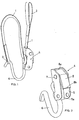
- fig. 1 is a perspective view of the belt according to the invention inserted into the buckle;
- fig. 2 is a view of the buckle.
- With reference to fig. 1, the tool according to the invention comprises a resistant belt (1) whose ends are folded and sewn to form two eyelets (2 and 3).
- The belt (1) is inserted into a buckle (4) made up of a box-like frame (5), that externally features a hook (6) and internally a transversal pivoting pin (7) for an oscillating clamp subjected to the constant thrust of a return spring (not shown in the enclosed drawings).
- The spiral spring is inserted into the pin (7) and exerts a pressure on the internal side of the clamp (8) that maintains the front edge (8a) of the clamp pressed against the bottom wall (5a) of the frame (5).
- In order to move the front edge (8a) away from the wall (5a) it is necessary to press the clamp (8) on its rear edge (8b) to win the resistance of the return spring.
- To use the tool according to the present invention, the operator simply introduces the hook (6) in the eyelet (3) of the belt (1) after wrapping the belt (1) around the object to be lifted in a safe grip.
- It must be stressed that the operator does not need to tighten the belt (1) since the belt itself will automatically tighten against the object when lifting it.
- As a matter of fact, when the hook of the lifting device inserted in the eyelet (2) of the belt (1) starts exerting a traction force upwards on the eyelet, the belt (1) starts sliding under the front edge of the clamp (8), thus progressively tightening the object wrapped with the section of belt between the hook (6) and the buckle (4).
- In order to loosen the belt (1) after moving the object, the operator simply presses the rear edge (8b) of the clamp (8) to allow the belt (1) to slide backwards inside the buckle (4) freely.
Claims (1)
- A weight-lifting belt provided with a self-locking buckle, wherein it comprises a resistant belt (1) ending with two eyelets (2 and 3) and inserted in a buckle (4) made up of a box-like frame (5), characterized in that the frame externally features a hook (6) and internally features a transversal pivoting pin (7) and an oscillating clamp (8), swiveling around said pin (7), the clamp (8) subjected to the constant thrust of a return spring exerting a pressure on the internal side of the clamp (8) that maintains the front edge (8a) of the clamp (8) pressed against the bottom wall (5a) of the frame (5).
Applications Claiming Priority (2)
| Application Number | Priority Date | Filing Date | Title |
|---|---|---|---|
| ITMC000001U | 2000-01-04 | ||
| IT2000MC000001U IT250834Y1 (en) | 2000-01-04 | 2000-01-04 | BELT FOR LIFTING WEIGHTS, EQUIPPED WITH A SELF-LOCKING BUCKLE. |
Publications (2)
| Publication Number | Publication Date |
|---|---|
| EP1114787A1 EP1114787A1 (en) | 2001-07-11 |
| EP1114787B1 true EP1114787B1 (en) | 2004-05-26 |
Family
ID=11443188
Family Applications (1)
| Application Number | Title | Priority Date | Filing Date |
|---|---|---|---|
| EP00830865A Expired - Lifetime EP1114787B1 (en) | 2000-01-04 | 2000-12-29 | A weight-lifting belt provided with self-locking buckle |
Country Status (4)
| Country | Link |
|---|---|
| EP (1) | EP1114787B1 (en) |
| AT (1) | ATE267765T1 (en) |
| DE (1) | DE60011027D1 (en) |
| IT (1) | IT250834Y1 (en) |
Families Citing this family (3)
| Publication number | Priority date | Publication date | Assignee | Title |
|---|---|---|---|---|
| CN105712182A (en) * | 2016-04-17 | 2016-06-29 | 昆山克鲁克机电设备有限公司 | Improved crane suspending belt adjusting device |
| CN106395606B (en) * | 2016-09-19 | 2018-03-06 | 重庆工商大学 | The quick tighting device for support of outdoor machine of air-conditioner |
| CN107934738A (en) * | 2017-10-24 | 2018-04-20 | 安徽德马泰格起重机械有限公司 | A kind of crane chain sling |
Family Cites Families (8)
| Publication number | Priority date | Publication date | Assignee | Title |
|---|---|---|---|---|
| GB329439A (en) * | 1929-03-21 | 1930-05-22 | William Howard Boase | An improved sling grip for handling goods |
| US3129031A (en) * | 1962-04-12 | 1964-04-14 | Cambridge Wire Cloth | Self releasing sling |
| DE1456464B2 (en) * | 1965-02-27 | 1970-02-26 | Göteborgs Bandväveri Aktiebolag, Göteborg (Schweden) | Automatic locking device for roundslings, especially sack slings |
| US3707022A (en) * | 1970-09-23 | 1972-12-26 | Alan Diehl | Tie down clamp |
| GB1515107A (en) * | 1975-11-18 | 1978-06-21 | Gyrac Eng Prod Ltd | Wire-rope slings |
| US4525007A (en) * | 1982-09-07 | 1985-06-25 | Chapalain Jean Pierre | Device for locking straps at the time of lifting loads, with possible adjustment of their useful length |
| US4915434A (en) * | 1987-05-02 | 1990-04-10 | Udo Dolezych | Apparatus for shortening and fastening a strap to wrap and hoist a load |
| JP2741245B2 (en) * | 1989-05-18 | 1998-04-15 | 三和テッキ株式会社 | Suspension equipment for cranes |
-
2000
- 2000-01-04 IT IT2000MC000001U patent/IT250834Y1/en active
- 2000-12-29 AT AT00830865T patent/ATE267765T1/en not_active IP Right Cessation
- 2000-12-29 EP EP00830865A patent/EP1114787B1/en not_active Expired - Lifetime
- 2000-12-29 DE DE60011027T patent/DE60011027D1/en not_active Expired - Lifetime
Also Published As
| Publication number | Publication date |
|---|---|
| ATE267765T1 (en) | 2004-06-15 |
| ITMC20000001U1 (en) | 2001-07-04 |
| DE60011027D1 (en) | 2004-07-01 |
| EP1114787A1 (en) | 2001-07-11 |
| IT250834Y1 (en) | 2003-10-14 |
Similar Documents
| Publication | Publication Date | Title |
|---|---|---|
| US7389971B2 (en) | Leverage tool for tightening devices | |
| CA2812544C (en) | Grabber | |
| US4116374A (en) | Cylinder carrying strap | |
| US7472916B2 (en) | Log hauler | |
| US4307635A (en) | Locking plier and adapter | |
| US2947514A (en) | Log binder | |
| US20060248990A1 (en) | Rescue tool for carrying a roof or sheet goods | |
| US4881434A (en) | Tool for threading oversized rope through opening in an elastic strap | |
| EP1114787B1 (en) | A weight-lifting belt provided with self-locking buckle | |
| CA3053832A1 (en) | Pipe lifter | |
| US4297916A (en) | Chain tightener attachment | |
| US5168783A (en) | Locking cable clamp | |
| US5429463A (en) | Load binder having removable handle | |
| US2515918A (en) | Hoisting tongs | |
| EP2513494A1 (en) | A clamping device | |
| HU182785B (en) | Automatic device for disengaging binding materials | |
| US3193253A (en) | Load sustaining device | |
| US4040754A (en) | Cable attachment | |
| US2903292A (en) | Releasing grip trip | |
| CA2577739A1 (en) | Leverage tool for tightening devices | |
| US6595490B1 (en) | Method and apparatus for winching | |
| US4869540A (en) | Pallet puller apparatus | |
| JP4627609B2 (en) | Clamp | |
| US4217071A (en) | Slip sheet repositioning apparatus | |
| EP2712835A1 (en) | Handle for lifting hook |
Legal Events
| Date | Code | Title | Description |
|---|---|---|---|
| PUAI | Public reference made under article 153(3) epc to a published international application that has entered the european phase |
Free format text: ORIGINAL CODE: 0009012 |
|
| AK | Designated contracting states |
Kind code of ref document: A1 Designated state(s): AT BE CH CY DE DK ES FI FR GB GR IE IT LI LU MC NL PT SE TR |
|
| AX | Request for extension of the european patent |
Free format text: AL;LT;LV;MK;RO;SI |
|
| AKX | Designation fees paid | ||
| REG | Reference to a national code |
Ref country code: DE Ref legal event code: 8566 |
|
| 17P | Request for examination filed |
Effective date: 20011224 |
|
| RBV | Designated contracting states (corrected) |
Designated state(s): AT BE CH CY DE DK ES FI FR GB GR IE IT LI LU MC NL PT SE TR |
|
| GRAP | Despatch of communication of intention to grant a patent |
Free format text: ORIGINAL CODE: EPIDOSNIGR1 |
|
| GRAS | Grant fee paid |
Free format text: ORIGINAL CODE: EPIDOSNIGR3 |
|
| GRAA | (expected) grant |
Free format text: ORIGINAL CODE: 0009210 |
|
| AK | Designated contracting states |
Kind code of ref document: B1 Designated state(s): AT BE CH CY DE DK ES FI FR GB GR IE IT LI LU MC NL PT SE TR |
|
| PG25 | Lapsed in a contracting state [announced via postgrant information from national office to epo] |
Ref country code: FR Free format text: LAPSE BECAUSE OF NON-PAYMENT OF DUE FEES Effective date: 20040526 Ref country code: AT Free format text: LAPSE BECAUSE OF FAILURE TO SUBMIT A TRANSLATION OF THE DESCRIPTION OR TO PAY THE FEE WITHIN THE PRESCRIBED TIME-LIMIT Effective date: 20040526 Ref country code: BE Free format text: LAPSE BECAUSE OF FAILURE TO SUBMIT A TRANSLATION OF THE DESCRIPTION OR TO PAY THE FEE WITHIN THE PRESCRIBED TIME-LIMIT Effective date: 20040526 Ref country code: CY Free format text: LAPSE BECAUSE OF FAILURE TO SUBMIT A TRANSLATION OF THE DESCRIPTION OR TO PAY THE FEE WITHIN THE PRESCRIBED TIME-LIMIT Effective date: 20040526 Ref country code: NL Free format text: LAPSE BECAUSE OF FAILURE TO SUBMIT A TRANSLATION OF THE DESCRIPTION OR TO PAY THE FEE WITHIN THE PRESCRIBED TIME-LIMIT Effective date: 20040526 Ref country code: TR Free format text: LAPSE BECAUSE OF FAILURE TO SUBMIT A TRANSLATION OF THE DESCRIPTION OR TO PAY THE FEE WITHIN THE PRESCRIBED TIME-LIMIT Effective date: 20040526 Ref country code: FI Free format text: LAPSE BECAUSE OF FAILURE TO SUBMIT A TRANSLATION OF THE DESCRIPTION OR TO PAY THE FEE WITHIN THE PRESCRIBED TIME-LIMIT Effective date: 20040526 |
|
| REG | Reference to a national code |
Ref country code: GB Ref legal event code: FG4D |
|
| REG | Reference to a national code |
Ref country code: CH Ref legal event code: EP |
|
| REG | Reference to a national code |
Ref country code: IE Ref legal event code: FG4D |
|
| REF | Corresponds to: |
Ref document number: 60011027 Country of ref document: DE Date of ref document: 20040701 Kind code of ref document: P |
|
| PG25 | Lapsed in a contracting state [announced via postgrant information from national office to epo] |
Ref country code: SE Free format text: LAPSE BECAUSE OF FAILURE TO SUBMIT A TRANSLATION OF THE DESCRIPTION OR TO PAY THE FEE WITHIN THE PRESCRIBED TIME-LIMIT Effective date: 20040826 Ref country code: DK Free format text: LAPSE BECAUSE OF FAILURE TO SUBMIT A TRANSLATION OF THE DESCRIPTION OR TO PAY THE FEE WITHIN THE PRESCRIBED TIME-LIMIT Effective date: 20040826 Ref country code: GR Free format text: LAPSE BECAUSE OF FAILURE TO SUBMIT A TRANSLATION OF THE DESCRIPTION OR TO PAY THE FEE WITHIN THE PRESCRIBED TIME-LIMIT Effective date: 20040826 |
|
| PG25 | Lapsed in a contracting state [announced via postgrant information from national office to epo] |
Ref country code: DE Free format text: LAPSE BECAUSE OF FAILURE TO SUBMIT A TRANSLATION OF THE DESCRIPTION OR TO PAY THE FEE WITHIN THE PRESCRIBED TIME-LIMIT Effective date: 20040827 |
|
| PG25 | Lapsed in a contracting state [announced via postgrant information from national office to epo] |
Ref country code: ES Free format text: LAPSE BECAUSE OF FAILURE TO SUBMIT A TRANSLATION OF THE DESCRIPTION OR TO PAY THE FEE WITHIN THE PRESCRIBED TIME-LIMIT Effective date: 20040906 |
|
| REG | Reference to a national code |
Ref country code: CH Ref legal event code: PL |
|
| NLV1 | Nl: lapsed or annulled due to failure to fulfill the requirements of art. 29p and 29m of the patents act | ||
| REG | Reference to a national code |
Ref country code: CH Ref legal event code: AEN Free format text: IL BREVETTO E STATO RIATTIVATO SECONDO LA DOMANDA DI PROSEGUIMENTO DELLA PROCEDURA DEL 19.11.2004. |
|
| PG25 | Lapsed in a contracting state [announced via postgrant information from national office to epo] |
Ref country code: LU Free format text: LAPSE BECAUSE OF NON-PAYMENT OF DUE FEES Effective date: 20041229 |
|
| PG25 | Lapsed in a contracting state [announced via postgrant information from national office to epo] |
Ref country code: IE Free format text: LAPSE BECAUSE OF NON-PAYMENT OF DUE FEES Effective date: 20041230 |
|
| PG25 | Lapsed in a contracting state [announced via postgrant information from national office to epo] |
Ref country code: CH Free format text: LAPSE BECAUSE OF NON-PAYMENT OF DUE FEES Effective date: 20041231 Ref country code: MC Free format text: LAPSE BECAUSE OF NON-PAYMENT OF DUE FEES Effective date: 20041231 Ref country code: LI Free format text: LAPSE BECAUSE OF NON-PAYMENT OF DUE FEES Effective date: 20041231 |
|
| PLBE | No opposition filed within time limit |
Free format text: ORIGINAL CODE: 0009261 |
|
| STAA | Information on the status of an ep patent application or granted ep patent |
Free format text: STATUS: NO OPPOSITION FILED WITHIN TIME LIMIT |
|
| 26N | No opposition filed |
Effective date: 20050301 |
|
| EN | Fr: translation not filed | ||
| REG | Reference to a national code |
Ref country code: CH Ref legal event code: PL |
|
| REG | Reference to a national code |
Ref country code: IE Ref legal event code: MM4A |
|
| GBPC | Gb: european patent ceased through non-payment of renewal fee |
Effective date: 20061229 |
|
| PG25 | Lapsed in a contracting state [announced via postgrant information from national office to epo] |
Ref country code: GB Free format text: LAPSE BECAUSE OF NON-PAYMENT OF DUE FEES Effective date: 20061229 |
|
| PG25 | Lapsed in a contracting state [announced via postgrant information from national office to epo] |
Ref country code: PT Free format text: LAPSE BECAUSE OF NON-PAYMENT OF DUE FEES Effective date: 20041026 |
|
| PGFP | Annual fee paid to national office [announced via postgrant information from national office to epo] |
Ref country code: IT Payment date: 20071227 Year of fee payment: 8 |
|
| PGFP | Annual fee paid to national office [announced via postgrant information from national office to epo] |
Ref country code: GB Payment date: 20060206 Year of fee payment: 6 |
|
| PG25 | Lapsed in a contracting state [announced via postgrant information from national office to epo] |
Ref country code: IT Free format text: LAPSE BECAUSE OF NON-PAYMENT OF DUE FEES Effective date: 20081229 |