EP1114781B1 - Tamper restistant bottle cap - Google Patents
Tamper restistant bottle cap Download PDFInfo
- Publication number
- EP1114781B1 EP1114781B1 EP00311474A EP00311474A EP1114781B1 EP 1114781 B1 EP1114781 B1 EP 1114781B1 EP 00311474 A EP00311474 A EP 00311474A EP 00311474 A EP00311474 A EP 00311474A EP 1114781 B1 EP1114781 B1 EP 1114781B1
- Authority
- EP
- European Patent Office
- Prior art keywords
- cap
- bottle
- neck
- lower extension
- ratchet
- Prior art date
- Legal status (The legal status is an assumption and is not a legal conclusion. Google has not performed a legal analysis and makes no representation as to the accuracy of the status listed.)
- Expired - Lifetime
Links
Images


Classifications
-
- B—PERFORMING OPERATIONS; TRANSPORTING
- B65—CONVEYING; PACKING; STORING; HANDLING THIN OR FILAMENTARY MATERIAL
- B65D—CONTAINERS FOR STORAGE OR TRANSPORT OF ARTICLES OR MATERIALS, e.g. BAGS, BARRELS, BOTTLES, BOXES, CANS, CARTONS, CRATES, DRUMS, JARS, TANKS, HOPPERS, FORWARDING CONTAINERS; ACCESSORIES, CLOSURES, OR FITTINGS THEREFOR; PACKAGING ELEMENTS; PACKAGES
- B65D41/00—Caps, e.g. crown caps or crown seals, i.e. members having parts arranged for engagement with the external periphery of a neck or wall defining a pouring opening or discharge aperture; Protective cap-like covers for closure members, e.g. decorative covers of metal foil or paper
- B65D41/32—Caps or cap-like covers with lines of weakness, tearing-strips, tags, or like opening or removal devices, e.g. to facilitate formation of pouring openings
- B65D41/325—Caps or cap-like covers with lines of weakness, tearing-strips, tags, or like opening or removal devices, e.g. to facilitate formation of pouring openings with integral internal sealing means
-
- B—PERFORMING OPERATIONS; TRANSPORTING
- B65—CONVEYING; PACKING; STORING; HANDLING THIN OR FILAMENTARY MATERIAL
- B65D—CONTAINERS FOR STORAGE OR TRANSPORT OF ARTICLES OR MATERIALS, e.g. BAGS, BARRELS, BOTTLES, BOXES, CANS, CARTONS, CRATES, DRUMS, JARS, TANKS, HOPPERS, FORWARDING CONTAINERS; ACCESSORIES, CLOSURES, OR FITTINGS THEREFOR; PACKAGING ELEMENTS; PACKAGES
- B65D41/00—Caps, e.g. crown caps or crown seals, i.e. members having parts arranged for engagement with the external periphery of a neck or wall defining a pouring opening or discharge aperture; Protective cap-like covers for closure members, e.g. decorative covers of metal foil or paper
- B65D41/32—Caps or cap-like covers with lines of weakness, tearing-strips, tags, or like opening or removal devices, e.g. to facilitate formation of pouring openings
- B65D41/34—Threaded or like caps or cap-like covers provided with tamper elements formed in, or attached to, the closure skirt
- B65D41/3404—Threaded or like caps or cap-like covers provided with tamper elements formed in, or attached to, the closure skirt with ratchet-and-pawl mechanism between the container and the closure skirt or the tamper element
- B65D41/3409—Threaded or like caps or cap-like covers provided with tamper elements formed in, or attached to, the closure skirt with ratchet-and-pawl mechanism between the container and the closure skirt or the tamper element the tamper element being integrally connected to the closure by means of bridges
-
- B—PERFORMING OPERATIONS; TRANSPORTING
- B65—CONVEYING; PACKING; STORING; HANDLING THIN OR FILAMENTARY MATERIAL
- B65D—CONTAINERS FOR STORAGE OR TRANSPORT OF ARTICLES OR MATERIALS, e.g. BAGS, BARRELS, BOTTLES, BOXES, CANS, CARTONS, CRATES, DRUMS, JARS, TANKS, HOPPERS, FORWARDING CONTAINERS; ACCESSORIES, CLOSURES, OR FITTINGS THEREFOR; PACKAGING ELEMENTS; PACKAGES
- B65D41/00—Caps, e.g. crown caps or crown seals, i.e. members having parts arranged for engagement with the external periphery of a neck or wall defining a pouring opening or discharge aperture; Protective cap-like covers for closure members, e.g. decorative covers of metal foil or paper
- B65D41/32—Caps or cap-like covers with lines of weakness, tearing-strips, tags, or like opening or removal devices, e.g. to facilitate formation of pouring openings
- B65D41/46—Snap-on caps or cap-like covers
- B65D41/48—Snap-on caps or cap-like covers non-metallic, e.g. made of paper or plastics
- B65D41/485—Snap-on caps or cap-like covers non-metallic, e.g. made of paper or plastics with integral internal sealing means
Definitions
- This invention relates to closure devices, and in particular, relates to an injection molded tamper resistant bottle cap for blow-molded bottles of the kind which are commonly used to hold and transport liquids, such as milk and juice.
- Injection molded caps for blow molded bottles have been used for many years.
- two types of bottle caps are available, push-on caps and thread-on caps.
- Push-on caps are installed by aligning the cap with the opening of a bottle and simply applying an axial force to the top of the cap.
- Thread-on caps generally require that the cap and bottle be aligned and that a rotative force be applied to the cap.
- threaded caps if carefully designed in conjunction with the bottle to which it is applied, can be made so that the rotative force required to install the cap is minimized or even eliminated.
- These kinds of injection molded caps are often made with low density polypropylene, a common material used in injection molding.
- One of the problems associated with injection molded caps relates to the tamper-evident connection which must be created between the bottle cap and bottle.
- One method of forming a tamper-evident connection is to use a threaded bottle cap which includes a ratchet ring having internal ratchet teeth in combination with a bottle neck having external ratchet teeth. When the bottle cap is screwed on the bottle neck, the ratchet teeth of the bottle cap ride over the mating ratchet teeth on the bottle neck, thereby enabling the bottle cap to be fully tightened on the bottle neck.
- the ratchet teeth of the bottle cap positively engage the mating ratchet teeth of the bottle neck, thereby preventing unthreading and unsealing of the cap.
- the ratchet ring breaks away from the bottle cap and the bottle cap may be unscrewed from the bottle neck. In this manner, removal of the ratchet ring from the bottle cap serves as visual evidence that the bottle has been opened.
- US-A-5,593,055 discloses a tamper-evident, snap-on, screw-off closure which is used with a specially shaped container neck.
- the neck has at least one first helical thread on a neck stretch portion, and at least one external ratchet tooth on a locking wall portion below the neck stretch.
- the closure has an upper skirt having at least one second helical thread mating with the first helical thread of the neck and a lower skirt with at least one internal ratchet tooth shaped and positioned to engage the external ratchet tooth when the closure is applied to the neck.
- the teeth formed on the skirt interior and neck exterior are arranged to provide at least one circumferentially extending stretch of the tamper-evident band where the teeth are not engaged.
- a line of weakness extending vertically through the disengaged stretch of the tamper-evident band is ruptured when the closure is unscrewed from the neck.
- the present invention is directed to a cap for a container, as set out in the accompanying claim 1.
- Subclaims 2 to 5 set out preferred features.
- the bottle cap may have a circular cover, a skirt depending from the periphery of the cover, and a tamper evidencing ring, in which the skirt of the bottle cap includes an interior surface having threads for retaining the cap to a bottle neck and a lower end having a circumferential flange with semi-circular outwardly extending tabs.
- the tamper evidencing ring of the bottle cap may include a plurality of ratchet teeth which are capable of meshing with a matching set of ratchet teeth on a bottle neck.
- the tamper evidencing ring may be connected to the flange by frangible connections between the outwardly extending tabs of the flange and the ratchet teeth of the tamper evidencing ring.
- Each of the frangible connections is generally defined by an area of overlap between a lower surface of each tab and an upper surface of each of the ratchet teeth of the tamper evidencing ring.
- tabs connected to ratchet teeth as a means for attaching the tamper evidencing ring to the skirt of the cap provides for a bottle cap that limits the ability of a person to pull the lower edge of the ratchet ring outward and upward toward the cover of the cap as the strong connections between the tabs and ratchet teeth resist twisting. Therefore, such a design of the bottle cap, wherein the attachment of the skirt and the tamper evidencing ring of the bottle cap is made by way of a connection between tabs and the ratchet teeth of the tamper evidencing ring, provides for a bottle cap having increased tamper resistance.
- the bottle neck may include an opening at its upper end, a cylindrical exterior surface having threads for retaining a bottle cap, a circumferential ratchet portion below the threads, and a circumferential transfer ring below the ratchet portion.
- the ratchet portion includes ratchet teeth which are capable of meshing with a matching set of ratchet teeth on a bottle cap.
- the circumferential transfer ring includes an annular top surface and an upwardly extending circumferential ridge on the periphery of the annular top surface.
- the threads of the bottle cap and the bottle neck may be appropriately dimensioned so as to sealingly engage when the bottle cap is screwed onto the bottle neck.
- a lower edge of the tamper evidencing ring is located adjacent the top surface of the transfer ring and the ratchet teeth of the bottle neck and the ratchet teeth of the bottle cap are engaged so as to prevent unscrewing of the bottle cap relative to the bottle neck without breaking the frangible connections.
- the location of the lower edge of the tamper evidencing ring adjacent the top surface of the transfer ring provides additional tamper resistance to the combination of the bottle cap and bottle neck.
- the ridge of the transfer ring completely surrounds the lower portion of the ratchet ring so that it is very difficult to insert a thin object, such as a fingernail, under the outer lower corner of the ratchet ring. Therefore, it is difficult to insert an object under the ratchet ring and pry the ratchet ring away from the bottle neck in an effort to defeat the locking action of the ratchet teeth of the ratchet ring and the ratchet teeth of the bottle neck.
- Figures 1 and 2 generally depict the outside of a bottle cap 11.
- the cap 11 is comprised of a circular cover 12 and a depending skirt 14 with knurls 15 formed on the outside surface thereof.
- a flange 16 is formed at the bottom of the skirt.
- the flange 16 includes a plurality of semi-circular outwardly directed tabs 17 which are equally spaced around the flange 16.
- a ratchet ring 18 including a plurality of ratchet teeth 20 is frangibly connected to the tabs 17 of the flange 16 by way of connections between each tab 17 and every other tooth 20 around the circumference of the flange 16.
- the ratchet ring 18 has a lower edge 21 and an outer edge 22 which meet in an outer lower corner 23 of the ratchet ring 18, as can be seen in Figure 4.
- Figure 3 shows the underside 24 of the cover 12.
- Four distinct threads 26 are formed on the inside surface of the skirt 14.
- a sealing plug 28 is also formed on the underside 24 of the cover 12.
- Bottle caps generally, and threaded caps in particular, tend to shrink most where there is substantial differential in volume of plastic material.
- Bottle caps which are injection molded tend to shrink in such a way as to deform an initially flat cover 12 into a dome-shaped surface.
- Significant volume of material is required to form threads which are sufficiently strong to hold the cap 11 in place.
- the cover 12, on the other hand, needs only to have sufficient thickness to withstand puncturing forces.
- the shrinkage of the cap 11 to form a dome (“doming") creates problems as it relates to dimensional stability and sealing effectiveness, and sometimes causes problems relating to the affixing of a label on the top of the cover 12. For example, radially inward shrinkage will tend to reduce the outside diameter of the plug 28.
- the cap 11 has means for limiting the doming of the cover 12.
- Four pairs of radial ribs 34 extend from the center of the underside 24 of the cover 12 to the plug 28.
- the radial ribs 34 provide the cover 12 with structural integrity sufficient to withstand the tendency for the cover 12 to assume a domed shape.
- the cover 12 by providing the cover 12 with additional volume of plastic material, the differential in material volume between the cover and the skirt is reduced, which tends to further reduce the distorting effects of shrinkage.
- FIG. 4 more clearly shows the location and configuration of the plug 28.
- the plug 28 is a generally circumferentially continuous formation integrally connected to the underside 24 of the cover 12.
- the plug 28 is disposed about the central axis 36 of the cap 11.
- the plug 28 has an outer surface 30 which is generally parabolic about the axis 36 and an inner surface 32 substantially parallel to the axis 36. It is important in order to achieve proper sealing that the surfaces which comprise the plug 28 be concentric about the central axis of the cap 11.
- the underside 24 of cover 12 does not include the plug 28 and the four pairs of radial ribs 34.
- the absence of a plug and radial ribs means that the cap could be used with a foil liner having a heat sensitive surface which can be heated into sealing engagement with the upper surface of a bottle neck by induction heating.
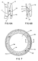
- FIGS 5, 6a and 6b more clearly show the configuration of the ratchet teeth 20 and the semi-circular outwardly directed tabs 17 of the flange 16.
- Each tooth 20 is comprised of a ramp surface 38 and an abutting surface 40.
- Arrow 42 indicates the direction in which the cap 11 moves when the cap 11 is installed or tightened.
- Arrow 44 indicates the direction required to unscrew the cap 11.
- the abutting surface 40 of the tooth 20 is sloped in such a way that the lower edge 46 of the tooth 20 is offset with respect to the upper portion 48 of the tooth 20 in the direction (Arrow 44) of unscrewing the cap 11.
- the lower edge 46 of the tooth 20 will engage the mating ratchet tooth first.
- the sloping nature of the abutting surface 40 will enhance the engagement of the tooth 20, and will resist unintended camming or slippage of the teeth 20 on the cap 11 relative to the matching ratchet teeth on the bottle neck.
- the ratchet teeth 20 of the cap will ride over the mating ratchet teeth on the bottle neck, and when the cap is turned in direction 44, the ratchet teeth 20 of the cap 11 will positively engage the mating ratchet teeth of the bottle neck.
- FIG 6A which is a bottom view of the tooth 20 shown in Figure 5, and Figure 6B, which is a top view of the tooth 20 shown in Figure 5, also show the attachment of the ratchet teeth 20 to the semi-circular outwardly directed tabs 17 of the flange 16.
- Each of the ratchet teeth 20 includes an upper surface 25 which is generally coplanar with the cover 12 of the cap 11.
- Each of the semi-circular outwardly directed tabs 17 of the flange 16 includes a lower surface 19 which is also generally coplanar with the cover 12 of the cap 11.
- the lower surface 19 of each tab 17 has an area substantially in the shape of a semicircle.
- Tabs 17 are shown as having the same vertical extent as the flange 16. However, the tabs may have a height which is less than the height of the flange 16.
- the tabs 17 and the ratchet teeth 20 are attached by way of a frangible connection between the lower surface 19 of each tab 17 and the upper surface 25 of each of the ratchet teeth 20. It can be seen from Figure 6A and 6B that the cross-sectional area of the frangible connection between a tab 17 and one of the ratchet teeth 20 is defined by the area wherein the lower surface 19 of each tab 17 and the upper surface 25 of each of the ratchet teeth 20 overlap.
- the adjustment of the area of overlap between the lower surface 19 of the tabs 17 and the upper surface 25 of the ratchet teeth 20 can be made using an injection molding die having portions which are movable with respect to each other.
- an injection molding die can be constructed wherein a first element of the die which molds the tabs 17 and a second element of the die which molds the ratchet teeth 20 are rotatable in relation to each other.
- the first and second element of the die are rotated so that the area of overlap between the lower surface 19 of each of the tabs 17 and the upper surface 25 of each of the ratchet teeth 20 is increased.
- the strength of the connection between the tabs 17 and the teeth 20 of the ratchet ring 18 can be decreased by decreasing the area of overlap between the lower surface 19 of each of the tabs 17 and the upper surface 25 of each of the ratchet teeth 20. Therefore, the use of tabs 17 connected to ratchet teeth 20 as a means for attaching the ratchet ring 18 to the skirt 14 of the cap 11 provides for a bottle cap design wherein the torque required to fracture the frangible connection between the skirt 14 and ratchet ring 18 can be precisely controlled.
- the means for attaching the ratchet ring 18 to the skirt 14 provides for a bottle cap design that limits the ability of a person to pull the lower edge 21 of the ratchet ring 18 outward and then upward toward the cover 12 of the cap 11 as the strong connections between the tabs 17 and ratchet teeth 20 resist twisting of the ratchet ring outward and upward.
- the need to adjust the strength of the connection between the ratchet ring and the skirt may arise from a change in the material used to form the cap.
- Low density polypropylene caps for example, will require more of an overlap (i.e., more cross-section area connecting) between the ratchet tooth and the bottom surface of the flange 16, than will caps made of high density polypropylene.
- the same tooling may be used and the change of materials may be accounted for by a simple relative rotation of the molds.
- Moving the mold for the ratchet ring relative to the molding for the body of the cap will cause an inward (or decrease) in the cross-sectional area of connecting material between the teeth and the tabs extending from the flange.
- moving the molds in a way which causes the ring 18 (in Figure 6A) to be formed in a position upwardly (as shown in Figure 6A) will reduce the area of connection.
- the attachment of the ratchet ring to the skirt in prior bottle cap designs is often accomplished by way of a number of thin stretchable strips of material which are connected to a bottom edge of the skirt and to an inner side surface of the ratchet teeth or an inner side surface of the ratchet ring.
- the ability to vary the strength of the thin connecting strips in these designs is quite limited as the area of overlap between the connecting strip and the skirt or ratchet ring cannot be easily varied.
- the thin strips of material connecting the skirt and ratchet ring are often weak and cannot resist twisting of the lower edge of the ratchet ring outward and then upward toward the cover of the cap.
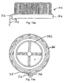
- the bottle 60 includes a body 62 and a cylindrical bottle neck 66 which is integral with the body 62.
- the bottle neck 66 has an upper opening 64 and an upper end 67 which terminates in an inwardly directed circumferential sealing lip 74 with an inner edge 76.
- the bottle neck 66 also includes four external screw threads 68 which engage threads 26 of bottle cap 11.
- the bottle neck 66 further includes a circumferential ratchet portion 70 having ratchet teeth 72.
- the ratchet teeth 72 engage the ratchet teeth 20 of the ratchet ring 18 of the bottle cap 11 when the bottle cap 11 is installed on the bottle neck 66.
- the ratchet teeth 72 are not arranged around the entire circumference of the ratchet portion 70, but are arranged in two groups, each of the two groups occupying an arc covering about one quarter of the circumference of the ratchet portion 70. It can be seen that the groups of ratchet teeth 72 are arranged on diametrically opposite sides of the bottle neck 66.
- the bottle neck 66 also includes a circumferential "bumper roll” or transfer ring 78 located below the ratchet portion 70.
- a bumper roll has been provided on a bottle neck for manufacturing purposes as it facilitates gripping the bottle during the filling operation and grabbing the bottle during the loading of the bottle into a shipping container.
- the bumper roll 78 of the bottle neck 66 of the present invention includes additional features which provide even further advantages.
- bumper roll 78 includes a substantially flat annular top surface 80 which has an upwardly extending circumferential ridge 82 along the entire length of its periphery.
- the top surface 80 of the bumper roll 78 is substantially parallel with respect to a plane defined by the opening 64 of the bottle neck 66.
- the top surface 80 of the bumper roll 78 is joined to a lower end 71 of the ratchet portion 70 and that the uppermost point of the ridge 82 of the bumper roll 78 is above the lower end 71 of the ratchet portion 70.
- a ridge 82 on the periphery of the top surface 80 of the bumper roll 78 serves to increase the resistance of the bottle neck 66 and bottle cap 11 to unwanted removal of the cap by an individual seeking to tamper with the contents of the bottle. Specifically, when bottle cap 11 is fully threaded onto bottle neck 66, the lower edge 21 of ratchet ring 18 is placed in contact with or closely adjacent to the top surface 80 of bumper roll 78, and the outer edge 22 of the ratchet ring 18 is placed adjacent to the inner surface 84 of ridge 82.
- the ridge 82 of the bumper roll 78 completely surrounds the lower portion of the ratchet ring 18 so that it is very difficult to insert a thin object, such as a fingernail, under the outer lower corner 23 of the ratchet ring 18. Therefore, the ridge 82 of the bumper roll 78 improves the tamper resistance of the bottle as it is extremely difficult to insert an object under the ratchet ring 18 and pry the ratchet ring 18 away from the bottle neck 66 in an effort to defeat the locking action of the ratchet teeth 20 of the ratchet ring 18 and the ratchet teeth 72 of the bottle neck 66.
- Figure 10 shows a cap 10a with a pull tab 19a extending outwardly from outer surface 22a of the ratchet ring 18a.
- the cap 10a of Figure 10 has ratchet teeth 20a, each of which is connected to a tab 17a, as opposed to every other ratchet tooth being connected as shown earlier.
- Figure 11 shows an assembly of a cap 10b and a liner 29 which is made of a foil and paper laminate capable of being connected by an induction heating process to the upper lip of a container neck.
- the cap 10b of Figure 11 has every other one of the ratchet teeth 20b connected via a tab 17b to the skirt 14b of the cap 10b.
- a pull tab 19b extends from the ratchet ring 18b.
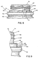
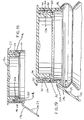
- Figures 12 and 13 are side and cross-sectional views of the cap 10b shown in Figure 11.
- the lines 29 shown as having been assembled by insertion past the threads 26b to a position adjacent to the underside 24b of the cover 12b.
- Figure 14 shows the cap 10b with lines 29 having been carried thereby into an assembled position in which the liner is affixed by induction heating to the top surface of a sealing lip 74 on a container neck 66.
- the fit between the cap 10b and the container neck 66 is such that threading of the cap 10b onto the neck 66 and the external threads 68 causes the lip 74 to be deflected in a resilient manner to a generally horizontal position so that an outer area of the lines 29 can come into firm contact with the top surface of the lip 74.
- This provides an area of contact by which a bond may be formed between a plastic layer.
- Film carried by the foil liner can fuse to the lip 74 upon being heated by induction heating after the cap 10b is threaded onto the neck 66.
- the shape of the pull tabs 19a and 19b, as shown in Figures 10 through 14, is like an inverted letter "J".
- a curved upper part 25 accommodates the ridge 82 formed on the bumper roll 78 to prevent stress and deformation in the ratchet ring 18b.
- the curved part 25 of the pull tab 19b extends initially upwardly from the outside of the ratchet ring 18b, then outwardly and finally downward and outward on an angle away from the bumper roll 78.
- FIGS 13a and 14a show a cap 10d which is helically threaded on the inside and has a plug 28d, as opposed to a foil liner for purposes of sealing a container neck.
- the cap 10d has a pull tab 19d which is attached to the upper edge of the ratchet ring 18d.
- the pull tab 19d also has a connecting web 31d which extends about 1/3 of the way down from the curved upper portion of the tab 19d to the free lower end of the tab 19d.
- the web 31d extends from the underside of the pull tab 19d and it point of connection to the upper portion of the ratchet ring 18d down to near the lower edge of the ratchet ring to facilitate twisting removal of the ratchet ring 18d by upward lifting of the pull tab 19d.
- the inside of the ratchet ring has a vertically oriented thin section 35 along which the web is aligned on outside surface of the ratchet ring. The point of attachment of the web is located in this manner to further facilitate the breaking and removal of the ratchet ring with the pull tab.
- the configuration of the ratchet ring 19d may also be advantageously used on push-on caps as described below to avoid entanglement of push-on caps as they are fed to a capping station in bottling line by an automatic feeding device. By locating the connection point of the pull tab near the top of the removable skirt of such caps there is no crevice for one cap to become "hung-up" on an adjacent cap.
- the web is vertically oriented and extending from an edge or side of the pull tab to a connection location extending vertically from a lower part of the ratchet ring (or removable skirt, in the case of a push-on cap) to the point at which the main portion of the pull tab interfaces horizontally with an upper portion of the ratchet ring.
- the web should be made with an opening 33 ( Figure 13a) to accommodate, i.e. not interfere with, the ridge (82 or 182) which extends upwardly from the bumper roll of the neck finish to which the cap is applied.
- An advantage of the present invention arises from the use of a pull tab which extends in the axial direction below the lower edge of the ratchet ring on a threaded cap.
- the pull tab may be used, as part of the feeding of the cap, to orient the threads of the cap in a particular way.
- one of the four threads may be designed to start (i.e. at its lower end) at a radial location adjacent to the pull tab; similarly, the threads of the neck finish with which such caps will be used may be molded so that the threads of the bottle neck will be well-aligned with the cap when the two components, i.e. the cap and the neck, are brought together in a capping operation.
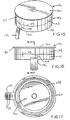
- Figures 15 through 19 show a further construction in that a push-on cap 10c is shown with a pull tab 19c.
- a cover 12c and a skirt 14c meet at an upper zone of the cap 10c, and a flange 27 extends laterally outwardly from the cover 12c. Gripping bumps 29 are formed on the inside surface of the pull tab 19c.
- the skirt 14c includes a lower section 101 and an upper section 103.
- a circumferential thin-walled connecting section 102 connects the upper section 103 to the lower section 101.
- a curved extension 104 of the thin-walled connecting section 102 extends from that section down to the lower edge 21c of the skirt 14c, whereby lifting of the pull tab 19c begins a tearing separation of the lower section 101 along section 104 which continues along section 102.
- the thickness of the skirt at section 104 and 102 is substantially less than the thickness of the skirt at other locations so that the tearing action initiated by lifting the pull tab 19c follows the line of weakness defined by section 104 and 102.
- the lower bead 127 formed on the inside of the lower section 101 is interrupted; this allows for the thin-walled section 104 to converge and continuously connect the lower edge 21c of the lower section 101 to the thin-walled section 102 which enables the lower section 101 to be completely and neatly separated from the upper section 103 of the skirt 14c.
- the cap 10c includes an integral plug element 128 which acts much like the plug 28 of the helically threaded cap described earlier. It will be recognized by those of ordinary skill in the art that either helically threaded caps or push-on caps may be made with or without an integral plug on the underside of the cover of such caps, and that a foil liner, of a type which may be bonded to a flange on the bottle neck by induction heating, may be used instead of an integral plug.
- the cap 10c is shown assembled, i.e., pushed on, to a container neck 166 of a bottle neck 160.
- the bottle neck 160 includes non-helical external threads or beads, i.e., upper bead 161 and lower bead 163, which engage internal threads or beads, i.e., upper bead 126 and lower bead 127, on the inside surface of the cap 10c.
- the cap 10c has a pull tab shaped to receive and accommodate a ridge 182 on a bumper roll 178.
- the curved upper part 25c of the pull tab 19c allow the pull tab 19c to project minimally in the outward direction from the bottle neck 166, while at the same time allowing the pull tab 19c to avoid stress and deformation which might prematurely bring the tearing action or separation of material along the thin-walled section 104.
- Blow-molded containers are often used by bottlers of milk and juice because they are inexpensive and relatively simple to manufacture. Indeed, many bottlers have blow-molding machines at their bottling facilities to even further reduce costs; making the bottles on-site saves in transportation costs relating to the shipment of bulky empty containers.
Landscapes
- Engineering & Computer Science (AREA)
- Mechanical Engineering (AREA)
- Closures For Containers (AREA)
Description
- This is a continuation-in-part application of parent application U.S. Serial No. 09/018,620 filed February 4, 1998.
- This invention relates to closure devices, and in particular, relates to an injection molded tamper resistant bottle cap for blow-molded bottles of the kind which are commonly used to hold and transport liquids, such as milk and juice.
- Injection molded caps for blow molded bottles have been used for many years. Generally, two types of bottle caps are available, push-on caps and thread-on caps. Push-on caps are installed by aligning the cap with the opening of a bottle and simply applying an axial force to the top of the cap. Thread-on caps generally require that the cap and bottle be aligned and that a rotative force be applied to the cap. In some cases, threaded caps, if carefully designed in conjunction with the bottle to which it is applied, can be made so that the rotative force required to install the cap is minimized or even eliminated. These kinds of injection molded caps are often made with low density polypropylene, a common material used in injection molding.
- One of the problems associated with injection molded caps relates to the tamper-evident connection which must be created between the bottle cap and bottle. One method of forming a tamper-evident connection is to use a threaded bottle cap which includes a ratchet ring having internal ratchet teeth in combination with a bottle neck having external ratchet teeth. When the bottle cap is screwed on the bottle neck, the ratchet teeth of the bottle cap ride over the mating ratchet teeth on the bottle neck, thereby enabling the bottle cap to be fully tightened on the bottle neck. However, when a user attempts to unscrew the bottle cap using low-to-medium twisting force, the ratchet teeth of the bottle cap positively engage the mating ratchet teeth of the bottle neck, thereby preventing unthreading and unsealing of the cap. When higher levels of twisting force are applied to the bottle cap in the direction of unscrewing, the ratchet ring breaks away from the bottle cap and the bottle cap may be unscrewed from the bottle neck. In this manner, removal of the ratchet ring from the bottle cap serves as visual evidence that the bottle has been opened.
- US-A-5,593,055 discloses a tamper-evident, snap-on, screw-off closure which is used with a specially shaped container neck. The neck has at least one first helical thread on a neck stretch portion, and at least one external ratchet tooth on a locking wall portion below the neck stretch. The closure has an upper skirt having at least one second helical thread mating with the first helical thread of the neck and a lower skirt with at least one internal ratchet tooth shaped and positioned to engage the external ratchet tooth when the closure is applied to the neck. The teeth formed on the skirt interior and neck exterior are arranged to provide at least one circumferentially extending stretch of the tamper-evident band where the teeth are not engaged. A line of weakness extending vertically through the disengaged stretch of the tamper-evident band is ruptured when the closure is unscrewed from the neck.
- While the combination of a bottle cap with a tamper evidencing ring and a bottle neck with ratchet teeth provides for an acceptable tamper-evident connection, this combination does have its limitations. Specifically, it may be possible for a person to pull the lower edge of the ratchet ring outward and then upward toward the cover of the bottle cap in order to defeat the locking action of the ratcket teeth of the bottle cap and bottle neck. It would then be possible to unscrew the bottle cap without breaking the ratchet ring away from the bottle cap and to screw the bottle cap back on the bottle neck. If this were to occur, there may be little visual evidence that the cap has been unscrewed and subsequently screwed back on the bottle neck. Therefore, present tamper-evident connections between a bottle cap and bottle neck may not provide optimum tamper resistance in certain circumstances.
- For the foregoing reasons, there was a need for an improved tamper resistant bottle cap and bottle neck which further limit the ability of a person to tamper with the contents of a bottle. Specifically, there was a need for a tamper resistant bottle cap and bottle neck which limit the ability of a person to pry a tamper evidencing ring with ratchet teeth away from the mating ratchet teeth on a bottle neck, unscrew the cap from the bottle neck, and subsequently screw the cap back on the bottle neck. A solution to this problem is disclosed in EP 0 941 938 A.
- It is a primary object of the present invention to provide an improved tamper resistant bottle cap comprising a pull tab.
- The present invention is directed to a cap for a container, as set out in the accompanying claim 1. Subclaims 2 to 5 set out preferred features. The bottle cap may have a circular cover, a skirt depending from the periphery of the cover, and a tamper evidencing ring, in which the skirt of the bottle cap includes an interior surface having threads for retaining the cap to a bottle neck and a lower end having a circumferential flange with semi-circular outwardly extending tabs. The tamper evidencing ring of the bottle cap may include a plurality of ratchet teeth which are capable of meshing with a matching set of ratchet teeth on a bottle neck. The tamper evidencing ring may be connected to the flange by frangible connections between the outwardly extending tabs of the flange and the ratchet teeth of the tamper evidencing ring. Each of the frangible connections is generally defined by an area of overlap between a lower surface of each tab and an upper surface of each of the ratchet teeth of the tamper evidencing ring.
- The use of tabs connected to ratchet teeth as a means for attaching the tamper evidencing ring to the skirt of the cap provides for a bottle cap that limits the ability of a person to pull the lower edge of the ratchet ring outward and upward toward the cover of the cap as the strong connections between the tabs and ratchet teeth resist twisting. Therefore, such a design of the bottle cap, wherein the attachment of the skirt and the tamper evidencing ring of the bottle cap is made by way of a connection between tabs and the ratchet teeth of the tamper evidencing ring, provides for a bottle cap having increased tamper resistance.
- The bottle neck may include an opening at its upper end, a cylindrical exterior surface having threads for retaining a bottle cap, a circumferential ratchet portion below the threads, and a circumferential transfer ring below the ratchet portion. The ratchet portion includes ratchet teeth which are capable of meshing with a matching set of ratchet teeth on a bottle cap. The circumferential transfer ring includes an annular top surface and an upwardly extending circumferential ridge on the periphery of the annular top surface.
- The threads of the bottle cap and the bottle neck may be appropriately dimensioned so as to sealingly engage when the bottle cap is screwed onto the bottle neck. After the bottle cap has been screwed onto the bottle neck, a lower edge of the tamper evidencing ring is located adjacent the top surface of the transfer ring and the ratchet teeth of the bottle neck and the ratchet teeth of the bottle cap are engaged so as to prevent unscrewing of the bottle cap relative to the bottle neck without breaking the frangible connections. The location of the lower edge of the tamper evidencing ring adjacent the top surface of the transfer ring provides additional tamper resistance to the combination of the bottle cap and bottle neck. Specifically, when the bottle cap is fully threaded onto the bottle neck, the ridge of the transfer ring completely surrounds the lower portion of the ratchet ring so that it is very difficult to insert a thin object, such as a fingernail, under the outer lower corner of the ratchet ring. Therefore, it is difficult to insert an object under the ratchet ring and pry the ratchet ring away from the bottle neck in an effort to defeat the locking action of the ratchet teeth of the ratchet ring and the ratchet teeth of the bottle neck.
- These and other features, aspects, objects, and advantages of the present invention will become better understood upon consideration of the following detailed description, appended claims and accompanying drawings. Figures 1-9 and 13a, 14a show background information. Figures 10-19 show embodiments of the present invention.
- Figure 1 is a perspective view of a bottle cap;
- Figure 2 is a top view of a bottle cap;
- Figure 3 is a bottom view of a bottle cap;
- Figure 4 is a cross-sectional view taken along line 4-4 of Figure 2;
- Figure 5 is an enlarged view taken along line 5-5 of Figure 3;
- Figure 6A is an enlarged bottom view of the tooth shown in Figure 5;
- Figure 6B is an enlarged top view of the tooth shown in Figure 5;
- Figure 7 is a top view of a bottle neck;
- Figure 8 is a side view of a bottle neck;
- Figure 9 is a cross-sectional view taken along line 9-9 of Figure 7;
- Figures 10 and 11 are perspective views of a helically threaded cap embodying the present invention, from above and below respectively, showing a pull tab adapted to accommodate a neck;
- Figures 12, 13 and 14 are side views of the cap shown in Figures 10 and 11, with Figures 13 and 14 being sectional views, and Figure 14 showing the cap as it sits on a bottle neck;
- Figures 13a and 14a are sectional views of a helically threaded cap, similar to the cap of Figures 13 and 14, wherein, however, the pull tab is configured so as to avoid difficulties related to automatic feeding of caps; this cap does not form part of the invention;
- Figures 15, 16 and 17 are perspective, side elevational and bottom plan views of a push-on cap of the present invention in which the cap has a pull tab configured to accommodate a neck finish; and
- Figures 18 and 19 are sectional views of the cap shown in Figures 15-17, with Figure 19 showing the cap in combination with a bottle neck.
-
- It should be understood that the drawings are not necessarily to scale and that the embodiments are sometimes illustrated by graphic symbols, phantom lines, diagrammatic representations and fragmentary views. In certain instances, details which are not necessary for an understanding of the present invention or which render other details difficult to perceive may have been omitted. It should be understood, of course, that the invention is not necessarily limited to the particular embodiments illustrated herein.
- Like reference numerals will be used to refer to like or similar parts from Figure to Figure in the following description of the drawings.
- Figures 1 and 2 generally depict the outside of a bottle cap 11. The cap 11 is comprised of a
circular cover 12 and a dependingskirt 14 withknurls 15 formed on the outside surface thereof. Aflange 16 is formed at the bottom of the skirt. Theflange 16 includes a plurality of semi-circular outwardly directedtabs 17 which are equally spaced around theflange 16. Aratchet ring 18 including a plurality ofratchet teeth 20 is frangibly connected to thetabs 17 of theflange 16 by way of connections between eachtab 17 and everyother tooth 20 around the circumference of theflange 16. Theratchet ring 18 has alower edge 21 and anouter edge 22 which meet in an outerlower corner 23 of theratchet ring 18, as can be seen in Figure 4. - Figure 3 shows the
underside 24 of thecover 12. Fourdistinct threads 26 are formed on the inside surface of theskirt 14. A sealingplug 28 is also formed on theunderside 24 of thecover 12. - Bottle caps generally, and threaded caps in particular, tend to shrink most where there is substantial differential in volume of plastic material. Bottle caps which are injection molded tend to shrink in such a way as to deform an initially
flat cover 12 into a dome-shaped surface. Significant volume of material is required to form threads which are sufficiently strong to hold the cap 11 in place. Thecover 12, on the other hand, needs only to have sufficient thickness to withstand puncturing forces. The shrinkage of the cap 11 to form a dome ("doming") creates problems as it relates to dimensional stability and sealing effectiveness, and sometimes causes problems relating to the affixing of a label on the top of thecover 12. For example, radially inward shrinkage will tend to reduce the outside diameter of theplug 28. To reduce the effects of such shrinkage, the cap 11 has means for limiting the doming of thecover 12. Four pairs ofradial ribs 34 extend from the center of theunderside 24 of thecover 12 to theplug 28. Theradial ribs 34 provide thecover 12 with structural integrity sufficient to withstand the tendency for thecover 12 to assume a domed shape. In addition, by providing thecover 12 with additional volume of plastic material, the differential in material volume between the cover and the skirt is reduced, which tends to further reduce the distorting effects of shrinkage. - Figure 4 more clearly shows the location and configuration of the
plug 28. Theplug 28 is a generally circumferentially continuous formation integrally connected to theunderside 24 of thecover 12. Theplug 28 is disposed about thecentral axis 36 of the cap 11. Theplug 28 has anouter surface 30 which is generally parabolic about theaxis 36 and aninner surface 32 substantially parallel to theaxis 36. It is important in order to achieve proper sealing that the surfaces which comprise theplug 28 be concentric about the central axis of the cap 11. - In an alternative construction, the
underside 24 ofcover 12 does not include theplug 28 and the four pairs ofradial ribs 34. The absence of a plug and radial ribs means that the cap could be used with a foil liner having a heat sensitive surface which can be heated into sealing engagement with the upper surface of a bottle neck by induction heating. - Figures 5, 6a and 6b more clearly show the configuration of the
ratchet teeth 20 and the semi-circular outwardly directedtabs 17 of theflange 16. Eachtooth 20 is comprised of aramp surface 38 and an abuttingsurface 40.Arrow 42 indicates the direction in which the cap 11 moves when the cap 11 is installed or tightened.Arrow 44 indicates the direction required to unscrew the cap 11. The abuttingsurface 40 of thetooth 20 is sloped in such a way that thelower edge 46 of thetooth 20 is offset with respect to theupper portion 48 of thetooth 20 in the direction (Arrow 44) of unscrewing the cap 11. As a result, as thetooth 20 engages a mating ratchet tooth on a bottle neck, thelower edge 46 of thetooth 20 will engage the mating ratchet tooth first. The sloping nature of the abuttingsurface 40 will enhance the engagement of thetooth 20, and will resist unintended camming or slippage of theteeth 20 on the cap 11 relative to the matching ratchet teeth on the bottle neck. Thus, when cap 11 is turned indirection 42, theratchet teeth 20 of the cap will ride over the mating ratchet teeth on the bottle neck, and when the cap is turned indirection 44, theratchet teeth 20 of the cap 11 will positively engage the mating ratchet teeth of the bottle neck. - Figure 6A, which is a bottom view of the
tooth 20 shown in Figure 5, and Figure 6B, which is a top view of thetooth 20 shown in Figure 5, also show the attachment of theratchet teeth 20 to the semi-circular outwardly directedtabs 17 of theflange 16. Each of theratchet teeth 20 includes anupper surface 25 which is generally coplanar with thecover 12 of the cap 11. Each of the semi-circular outwardly directedtabs 17 of theflange 16 includes alower surface 19 which is also generally coplanar with thecover 12 of the cap 11. Thelower surface 19 of eachtab 17 has an area substantially in the shape of a semicircle. -
Tabs 17 are shown as having the same vertical extent as theflange 16. However, the tabs may have a height which is less than the height of theflange 16. - The
tabs 17 and theratchet teeth 20 are attached by way of a frangible connection between thelower surface 19 of eachtab 17 and theupper surface 25 of each of theratchet teeth 20. It can be seen from Figure 6A and 6B that the cross-sectional area of the frangible connection between atab 17 and one of theratchet teeth 20 is defined by the area wherein thelower surface 19 of eachtab 17 and theupper surface 25 of each of theratchet teeth 20 overlap. It can be appreciated that by varying the area of overlap between thelower surface 19 of eachtab 17 and theupper surface 25 of each of theratchet teeth 20, the strength of the frangible connection between thetabs 17 and theratchet teeth 20 can be adjusted, as a frangible connection having a greater cross-sectional area will require a greater force in order to fracture the connection. - The adjustment of the area of overlap between the
lower surface 19 of thetabs 17 and theupper surface 25 of theratchet teeth 20 can be made using an injection molding die having portions which are movable with respect to each other. Namely, an injection molding die can be constructed wherein a first element of the die which molds thetabs 17 and a second element of the die which molds theratchet teeth 20 are rotatable in relation to each other. When a bottle cap having stronger connections between thetabs 17 and theteeth 20 of theratchet ring 18 is desired, the first and second element of the die are rotated so that the area of overlap between thelower surface 19 of each of thetabs 17 and theupper surface 25 of each of theratchet teeth 20 is increased. In a similar manner, the strength of the connection between thetabs 17 and theteeth 20 of theratchet ring 18 can be decreased by decreasing the area of overlap between thelower surface 19 of each of thetabs 17 and theupper surface 25 of each of theratchet teeth 20. Therefore, the use oftabs 17 connected to ratchetteeth 20 as a means for attaching theratchet ring 18 to theskirt 14 of the cap 11 provides for a bottle cap design wherein the torque required to fracture the frangible connection between theskirt 14 and ratchetring 18 can be precisely controlled. In addition, the means for attaching theratchet ring 18 to theskirt 14 provides for a bottle cap design that limits the ability of a person to pull thelower edge 21 of theratchet ring 18 outward and then upward toward thecover 12 of the cap 11 as the strong connections between thetabs 17 and ratchetteeth 20 resist twisting of the ratchet ring outward and upward. - The need to adjust the strength of the connection between the ratchet ring and the skirt may arise from a change in the material used to form the cap. Low density polypropylene caps, for example, will require more of an overlap (i.e., more cross-section area connecting) between the ratchet tooth and the bottom surface of the
flange 16, than will caps made of high density polypropylene. Thus, if a customer's application calls for a cap made of a material different from the material used to make a previous cap, the same tooling may be used and the change of materials may be accounted for by a simple relative rotation of the molds. Moving the mold for the ratchet ring relative to the molding for the body of the cap will cause an inward (or decrease) in the cross-sectional area of connecting material between the teeth and the tabs extending from the flange. Specifically, for example, moving the molds in a way which causes the ring 18 (in Figure 6A) to be formed in a position upwardly (as shown in Figure 6A) will reduce the area of connection. - In contrast, the attachment of the ratchet ring to the skirt in prior bottle cap designs is often accomplished by way of a number of thin stretchable strips of material which are connected to a bottom edge of the skirt and to an inner side surface of the ratchet teeth or an inner side surface of the ratchet ring. The ability to vary the strength of the thin connecting strips in these designs is quite limited as the area of overlap between the connecting strip and the skirt or ratchet ring cannot be easily varied. Furthermore, the thin strips of material connecting the skirt and ratchet ring are often weak and cannot resist twisting of the lower edge of the ratchet ring outward and then upward toward the cover of the cap.
- Referring now to Figures 7, 8 and 9 there is shown a bottle, indicated generally at 60, upon which the bottle cap 11 may be installed. The
bottle 60 includes abody 62 and acylindrical bottle neck 66 which is integral with thebody 62. Thebottle neck 66 has anupper opening 64 and anupper end 67 which terminates in an inwardly directedcircumferential sealing lip 74 with aninner edge 76. Thebottle neck 66 also includes fourexternal screw threads 68 which engagethreads 26 of bottle cap 11. - The
bottle neck 66 further includes acircumferential ratchet portion 70 havingratchet teeth 72. Theratchet teeth 72 engage theratchet teeth 20 of theratchet ring 18 of the bottle cap 11 when the bottle cap 11 is installed on thebottle neck 66. In the preferred embodiment shown in Figure 7, theratchet teeth 72 are not arranged around the entire circumference of theratchet portion 70, but are arranged in two groups, each of the two groups occupying an arc covering about one quarter of the circumference of theratchet portion 70. It can be seen that the groups ofratchet teeth 72 are arranged on diametrically opposite sides of thebottle neck 66. - The
bottle neck 66 also includes a circumferential "bumper roll" ortransfer ring 78 located below theratchet portion 70. In prior bottle neck designs, a bumper roll has been provided on a bottle neck for manufacturing purposes as it facilitates gripping the bottle during the filling operation and grabbing the bottle during the loading of the bottle into a shipping container. However, thebumper roll 78 of thebottle neck 66 of the present invention includes additional features which provide even further advantages. - It can be seen from Figures 7, 8 and 9 that
bumper roll 78 includes a substantially flat annulartop surface 80 which has an upwardly extendingcircumferential ridge 82 along the entire length of its periphery. Preferably, thetop surface 80 of thebumper roll 78 is substantially parallel with respect to a plane defined by theopening 64 of thebottle neck 66. Also, it is preferred that thetop surface 80 of thebumper roll 78 is joined to alower end 71 of theratchet portion 70 and that the uppermost point of theridge 82 of thebumper roll 78 is above thelower end 71 of theratchet portion 70. The placement of aridge 82 on the periphery of thetop surface 80 of thebumper roll 78 serves to increase the resistance of thebottle neck 66 and bottle cap 11 to unwanted removal of the cap by an individual seeking to tamper with the contents of the bottle. Specifically, when bottle cap 11 is fully threaded ontobottle neck 66, thelower edge 21 ofratchet ring 18 is placed in contact with or closely adjacent to thetop surface 80 ofbumper roll 78, and theouter edge 22 of theratchet ring 18 is placed adjacent to theinner surface 84 ofridge 82. In this arrangement of theratchet ring 18 of the bottle cap 11 and thebumper roll 78 ofbottle neck 66, theridge 82 of thebumper roll 78 completely surrounds the lower portion of theratchet ring 18 so that it is very difficult to insert a thin object, such as a fingernail, under the outerlower corner 23 of theratchet ring 18. Therefore, theridge 82 of thebumper roll 78 improves the tamper resistance of the bottle as it is extremely difficult to insert an object under theratchet ring 18 and pry theratchet ring 18 away from thebottle neck 66 in an effort to defeat the locking action of theratchet teeth 20 of theratchet ring 18 and theratchet teeth 72 of thebottle neck 66. - Thus, it is seen that an improved tamper resistant bottle cap and neck are provided which satisfy the need for a bottle with an improved tamper resistant seal.
- Figure 10 shows a
cap 10a with apull tab 19a extending outwardly from outer surface 22a of the ratchet ring 18a. Thecap 10a of Figure 10 hasratchet teeth 20a, each of which is connected to atab 17a, as opposed to every other ratchet tooth being connected as shown earlier. - Figure 11 shows an assembly of a cap 10b and a
liner 29 which is made of a foil and paper laminate capable of being connected by an induction heating process to the upper lip of a container neck. The cap 10b of Figure 11 has every other one of theratchet teeth 20b connected via a tab 17b to theskirt 14b of the cap 10b. A pull tab 19b extends from the ratchet ring 18b. - Figures 12 and 13 are side and cross-sectional views of the cap 10b shown in Figure 11. In Figures 12 and 13, the
lines 29 shown as having been assembled by insertion past the threads 26b to a position adjacent to theunderside 24b of the cover 12b. - Figure 14 shows the cap 10b with
lines 29 having been carried thereby into an assembled position in which the liner is affixed by induction heating to the top surface of a sealinglip 74 on acontainer neck 66. The fit between the cap 10b and thecontainer neck 66 is such that threading of the cap 10b onto theneck 66 and theexternal threads 68 causes thelip 74 to be deflected in a resilient manner to a generally horizontal position so that an outer area of thelines 29 can come into firm contact with the top surface of thelip 74. This provides an area of contact by which a bond may be formed between a plastic layer. Film carried by the foil liner can fuse to thelip 74 upon being heated by induction heating after the cap 10b is threaded onto theneck 66. - The shape of the
pull tabs 19a and 19b, as shown in Figures 10 through 14, is like an inverted letter "J". A curvedupper part 25 accommodates theridge 82 formed on thebumper roll 78 to prevent stress and deformation in the ratchet ring 18b. Thecurved part 25 of the pull tab 19b extends initially upwardly from the outside of the ratchet ring 18b, then outwardly and finally downward and outward on an angle away from thebumper roll 78. - Figures 13a and 14a, show a cap 10d which is helically threaded on the inside and has a
plug 28d, as opposed to a foil liner for purposes of sealing a container neck. The cap 10d has a pull tab 19d which is attached to the upper edge of theratchet ring 18d. The pull tab 19d also has a connectingweb 31d which extends about 1/3 of the way down from the curved upper portion of the tab 19d to the free lower end of the tab 19d. By connecting the tab 19d to the upper portion of theratchet ring 18d, there is less likelihood for adjacent caps in an automatic feeding device to become entangled. Theweb 31d extends from the underside of the pull tab 19d and it point of connection to the upper portion of theratchet ring 18d down to near the lower edge of the ratchet ring to facilitate twisting removal of theratchet ring 18d by upward lifting of the pull tab 19d. The inside of the ratchet ring has a vertically orientedthin section 35 along which the web is aligned on outside surface of the ratchet ring. The point of attachment of the web is located in this manner to further facilitate the breaking and removal of the ratchet ring with the pull tab. - It should be noted that the configuration of the ratchet ring 19d may also be advantageously used on push-on caps as described below to avoid entanglement of push-on caps as they are fed to a capping station in bottling line by an automatic feeding device. By locating the connection point of the pull tab near the top of the removable skirt of such caps there is no crevice for one cap to become "hung-up" on an adjacent cap. In both instances, the web is vertically oriented and extending from an edge or side of the pull tab to a connection location extending vertically from a lower part of the ratchet ring (or removable skirt, in the case of a push-on cap) to the point at which the main portion of the pull tab interfaces horizontally with an upper portion of the ratchet ring. The web should be made with an opening 33 (Figure 13a) to accommodate, i.e. not interfere with, the ridge (82 or 182) which extends upwardly from the bumper roll of the neck finish to which the cap is applied.
- An advantage of the present invention arises from the use of a pull tab which extends in the axial direction below the lower edge of the ratchet ring on a threaded cap. The pull tab may be used, as part of the feeding of the cap, to orient the threads of the cap in a particular way. For example in a four-thread cap, one of the four threads may be designed to start (i.e. at its lower end) at a radial location adjacent to the pull tab; similarly, the threads of the neck finish with which such caps will be used may be molded so that the threads of the bottle neck will be well-aligned with the cap when the two components, i.e. the cap and the neck, are brought together in a capping operation. By using the pull tab to control the relative positions of the thread on the cap and the bottle neck, misalignment and cross-threading can be minimized or even eliminated. This advantage, the proper alignment of threads on the cap and neck, can greatly reduce the potential for jamming and line stoppage in a bottling facility.
- Figures 15 through 19 show a further construction in that a push-on cap 10c is shown with a
pull tab 19c. A cover 12c and a skirt 14c meet at an upper zone of the cap 10c, and aflange 27 extends laterally outwardly from the cover 12c. Grippingbumps 29 are formed on the inside surface of thepull tab 19c. The skirt 14c includes alower section 101 and anupper section 103. A circumferential thin-walled connectingsection 102 connects theupper section 103 to thelower section 101. Acurved extension 104 of the thin-walled connectingsection 102 extends from that section down to the lower edge 21c of the skirt 14c, whereby lifting of thepull tab 19c begins a tearing separation of thelower section 101 alongsection 104 which continues alongsection 102. The thickness of the skirt atsection pull tab 19c follows the line of weakness defined bysection - As can be seen in Figure 18, the
lower bead 127 formed on the inside of thelower section 101 is interrupted; this allows for the thin-walled section 104 to converge and continuously connect the lower edge 21c of thelower section 101 to the thin-walled section 102 which enables thelower section 101 to be completely and neatly separated from theupper section 103 of the skirt 14c. - As can be seen in Figures 17 through 19, the cap 10c includes an
integral plug element 128 which acts much like theplug 28 of the helically threaded cap described earlier. It will be recognized by those of ordinary skill in the art that either helically threaded caps or push-on caps may be made with or without an integral plug on the underside of the cover of such caps, and that a foil liner, of a type which may be bonded to a flange on the bottle neck by induction heating, may be used instead of an integral plug. - In Figure 19, the cap 10c is shown assembled, i.e., pushed on, to a container neck 166 of a bottle neck 160. The bottle neck 160 includes non-helical external threads or beads, i.e.,
upper bead 161 andlower bead 163, which engage internal threads or beads, i.e.,upper bead 126 andlower bead 127, on the inside surface of the cap 10c. As with the helically threaded embodiment described earlier, the cap 10c has a pull tab shaped to receive and accommodate a ridge 182 on a bumper roll 178. The curved upper part 25c of thepull tab 19c allow thepull tab 19c to project minimally in the outward direction from the bottle neck 166, while at the same time allowing thepull tab 19c to avoid stress and deformation which might prematurely bring the tearing action or separation of material along the thin-walled section 104. - The invention described herein will have its most common application in containers made by a blow-molding method. Blow-molded containers are often used by bottlers of milk and juice because they are inexpensive and relatively simple to manufacture. Indeed, many bottlers have blow-molding machines at their bottling facilities to even further reduce costs; making the bottles on-site saves in transportation costs relating to the shipment of bulky empty containers.
- Although the present invention has been described in considerable detail with reference to certain preferred embodiments, one skilled in the art will appreciate that the present invention can be practiced by other than the preferred embodiments, which have been presented- for purposes of illustration and not of limitation.
Claims (5)
- A cap (10a, 10b or 10c) for a container (60) having a neck, said cap comprising a lid portion (12) and an axially downwardly extending skirt (14), said skirt (14) having an internal formation (26) which engages a corresponding forming on an external portion (68) of the container neck (66), said skirt (14) having a breakable lower extension (18), a pull tab (19) connected to said lower extension (18), said pull tab (19) having a laterally extending part and an axially downwardly extending part, whereby said pull tab (19) extends from said lower extension (18), characterised in that said pull tab (19) has a curved part (25) extending initially upwardly from the outside of said lower extension (18), then outwardly and finally downwardly to form a recess for accomodating a ridge (82) formed on a shoulder (78) of said container when the cap is fully threaded onto the container neck and thus a lower edge (21) of said lower extension (18) is placed in contact with or closely adjacent to a top surface (80) of said shoulder (78), and an outer edge (22) of the lower extension (18) is placed adjacent to an inner surface (84) of said ridge (82).
- A cap in accordance with claim 1, characterised in that said pull tab (19) is connected to a mid-height area of said lower extension (18).
- A cap in accordance with claim 2, characterised in that said internal formation (26) on said cap (10) includes at least one thread, and said lower extension (18) includes ramped ratchet teeth (20) which prevent unscrewing of said cap (10) after said cap (10) is placed on said container (60) unless said lower extension (18) is at least partially broken away from said skirt (14).
- A cap in accordance with claim 2, characterised in that said internal formation (26) on said cap (10) includes at least one bead which engages a corresponding bead on said neck (66), said beads being non-helical.
- A cap in accordance with claim 1, characterised in that said pull tab (19) is integrally formed with and extends from an area above said lower edge (21) of said lower extension (18) and extends laterally over said wall (84) and downwardly past said wall (84) to an elevation below said lower extension (18).
Applications Claiming Priority (2)
| Application Number | Priority Date | Filing Date | Title |
|---|---|---|---|
| US09/467,433 US6523710B1 (en) | 1998-02-04 | 1999-12-20 | Tamper resistant bottle cap and neck |
| US467433 | 1999-12-20 |
Publications (3)
| Publication Number | Publication Date |
|---|---|
| EP1114781A2 EP1114781A2 (en) | 2001-07-11 |
| EP1114781A3 EP1114781A3 (en) | 2002-11-13 |
| EP1114781B1 true EP1114781B1 (en) | 2005-03-30 |
Family
ID=23855683
Family Applications (1)
| Application Number | Title | Priority Date | Filing Date |
|---|---|---|---|
| EP00311474A Expired - Lifetime EP1114781B1 (en) | 1999-12-20 | 2000-12-20 | Tamper restistant bottle cap |
Country Status (5)
| Country | Link |
|---|---|
| US (1) | US6523710B1 (en) |
| EP (1) | EP1114781B1 (en) |
| DE (1) | DE60019077T2 (en) |
| ES (1) | ES2238976T3 (en) |
| GB (1) | GB2358182C (en) |
Families Citing this family (30)
| Publication number | Priority date | Publication date | Assignee | Title |
|---|---|---|---|---|
| GB2383995B (en) * | 2002-01-11 | 2005-12-07 | Portola Packaging Ltd | Closure with pressure release system |
| US6988642B2 (en) * | 2002-10-29 | 2006-01-24 | Johnson & Johnson Consumer Companies | Tamper-evident dispenser bottle |
| GB2399559B (en) * | 2003-02-20 | 2006-07-26 | Preton Ltd | Construction of container |
| US6931821B2 (en) | 2003-07-29 | 2005-08-23 | Evergreen Industries, Inc. | Tamper evident vial cap and integrity assurance method |
| AU2005209675B2 (en) * | 2004-11-18 | 2011-12-08 | Pathtainer Systems International Pty Ltd | Two-part closure for a container |
| DE602005012776D1 (en) * | 2004-11-18 | 2009-04-02 | Pathtainer Systems Internat Pt | Two-piece closure for a container |
| US20070034590A1 (en) * | 2005-08-04 | 2007-02-15 | Hidding Douglas J | Bottle with retained ring finish feature |
| US7581652B2 (en) * | 2005-08-09 | 2009-09-01 | Rexam Closure Systems Inc. | Tamper-indicating package, and a closure and container for such a package |
| US20070051690A1 (en) * | 2005-09-08 | 2007-03-08 | Hidding Douglas J | Cap with visible tamper-indicating seal |
| US20070051691A1 (en) * | 2005-09-08 | 2007-03-08 | Hidding Douglas J | Cap with visible tamper-indicating seal |
| US7713055B2 (en) * | 2005-10-18 | 2010-05-11 | Milacron Llc | Blow mold assembly |
| US20070272647A1 (en) * | 2006-03-31 | 2007-11-29 | Long Charles J | Closure with vertical tear bands |
| JP4757122B2 (en) * | 2006-07-07 | 2011-08-24 | ヱスビー食品株式会社 | Cap locking device |
| WO2008027044A1 (en) * | 2006-09-01 | 2008-03-06 | Owens-Illinois Closure Inc. | Tamper-indicating package, and a closure and container for such a package |
| US8118182B1 (en) * | 2007-08-02 | 2012-02-21 | Robert Licari | Ergonomic beverage container |
| US20090277861A1 (en) * | 2008-05-08 | 2009-11-12 | Long Jr Charles J | Closure with tamper evident strip |
| US20110174761A1 (en) * | 2008-05-19 | 2011-07-21 | Omega Cap Solutions, LLC | Visual tamper-evident conical screw cap and neck finish |
| US20090283492A1 (en) * | 2008-05-19 | 2009-11-19 | Omega Cap Solutions Llc | Visual Tamper-Evident Conical Screw Cap and Neck Finish |
| US8839976B2 (en) * | 2010-06-14 | 2014-09-23 | Glenn H. Morris, Jr. | Locking lid container |
| US20120031871A1 (en) | 2010-08-04 | 2012-02-09 | Omega Cap Soultions LLC | Step twist zipped visual tamper-evident cap and neck finish |
| ITMI20120443A1 (en) * | 2012-03-21 | 2013-09-22 | Roem S R L | IMPROVED ENCLOSURE FOR CONTAINERS |
| PE20170614A1 (en) * | 2014-10-07 | 2017-05-24 | Stanpac Inc | LID WITH EVIDENCE OF HANDLING AND ITS MANUFACTURING METHOD |
| US11214410B2 (en) * | 2016-02-02 | 2022-01-04 | Niagara Bottling, Llc | Tamper evidence container closure |
| BR112018015742A2 (en) * | 2016-02-02 | 2019-01-08 | Clarke Hanan Jay | tamper evidence bridges |
| USD908495S1 (en) * | 2017-06-07 | 2021-01-26 | Silgan White Cap LLC | Closure |
| US11597556B2 (en) | 2018-07-30 | 2023-03-07 | Niagara Bottling, Llc | Container preform with tamper evidence finish portion |
| USD1023755S1 (en) * | 2019-06-03 | 2024-04-23 | Berlin Packaging, Llc | Tamper evident closure assembly |
| USD1014251S1 (en) * | 2019-06-03 | 2024-02-13 | Berlin Packaging, Llc | Tamper evident closure assembly |
| CN114174191A (en) * | 2019-07-22 | 2022-03-11 | 萨克米伊莫拉机械合作社合作公司 | Combined cap, cap and neck structure for closing container |
| CN111268271A (en) * | 2020-03-26 | 2020-06-12 | 江苏华兰药用新材料股份有限公司 | Bottle cap and bottle combined structure |
Family Cites Families (17)
| Publication number | Priority date | Publication date | Assignee | Title |
|---|---|---|---|---|
| US4032029A (en) * | 1976-04-05 | 1977-06-28 | Benjamin Arthur Cochrane | Tamper-proof bottle cap and container |
| GB2064493A (en) * | 1979-11-06 | 1981-06-17 | Massmould Ltd | Tamper-indicating bottle caps |
| EP0050490B1 (en) * | 1980-10-17 | 1986-08-27 | U.G. CLOSURES & PLASTICS LIMITED | Sterile pack |
| GB2199571A (en) * | 1987-01-08 | 1988-07-13 | Metal Closures Ltd | Closures for containers |
| US4815620A (en) * | 1987-09-25 | 1989-03-28 | Cap Snap, Inc. | Tamper-evident cap having plural diameters |
| US4922684A (en) * | 1988-01-15 | 1990-05-08 | Pi, Inc. | Caps for milk bottles and an applicator for placing caps on bottles |
| US4930647A (en) * | 1989-01-24 | 1990-06-05 | Continental Plastics, Inc. | Tamper indicating closure system utilizing axially extending ratchet |
| US4934546A (en) * | 1989-01-30 | 1990-06-19 | Cap Snap Co. | Tamper evident cap having lift tab on bottom edge |
| US4903849A (en) * | 1989-04-24 | 1990-02-27 | Irwin Wallman | Tamper evident cap and bottle |
| US5975320A (en) * | 1990-08-09 | 1999-11-02 | Portola Packaging, Inc. | Tamper-evident closures and container neck therefor |
| US5975321A (en) * | 1990-08-09 | 1999-11-02 | Portola Packaging, Inc. | Snap-on, screw-off cap with tamper-evidencing skirt and container neck |
| US5213224A (en) * | 1990-08-09 | 1993-05-25 | Portola Packaging, Inc. | Snap-on, screw-off cap and container neck |
| US5593055A (en) * | 1990-08-09 | 1997-01-14 | Portola Packaging, Inc. | Snap-on, screw-off cap with tamper-evident skirt and container neck |
| US5092478A (en) * | 1991-05-20 | 1992-03-03 | Pierre Maurice | Tamper-evident tear-off strip for container cap |
| US5775528A (en) * | 1995-08-21 | 1998-07-07 | Superseal Corporation | Snap-on/screw-off cap and neck configuration |
| US5642825A (en) * | 1995-08-21 | 1997-07-01 | Superseal Corporation | Container closure having peripheral tamper-indicator |
| US6003701A (en) * | 1998-02-04 | 1999-12-21 | Hidding; Walter E. | Tamper resistant bottle cap and neck |
-
1999
- 1999-12-20 US US09/467,433 patent/US6523710B1/en not_active Expired - Lifetime
-
2000
- 2000-12-18 GB GB0030847A patent/GB2358182C/en not_active Expired - Fee Related
- 2000-12-20 ES ES00311474T patent/ES2238976T3/en not_active Expired - Lifetime
- 2000-12-20 EP EP00311474A patent/EP1114781B1/en not_active Expired - Lifetime
- 2000-12-20 DE DE60019077T patent/DE60019077T2/en not_active Expired - Lifetime
Also Published As
| Publication number | Publication date |
|---|---|
| DE60019077D1 (en) | 2005-05-04 |
| DE60019077T2 (en) | 2005-09-01 |
| GB0030847D0 (en) | 2001-01-31 |
| GB2358182B (en) | 2004-01-07 |
| EP1114781A2 (en) | 2001-07-11 |
| US6523710B1 (en) | 2003-02-25 |
| GB2358182C (en) | 2007-11-06 |
| EP1114781A3 (en) | 2002-11-13 |
| ES2238976T3 (en) | 2005-09-16 |
| GB2358182A (en) | 2001-07-18 |
Similar Documents
| Publication | Publication Date | Title |
|---|---|---|
| EP1114781B1 (en) | Tamper restistant bottle cap | |
| US6003701A (en) | Tamper resistant bottle cap and neck | |
| US5307945A (en) | Closure | |
| US5456376A (en) | Snap-on, screw off cap and container neck | |
| US6439412B2 (en) | Snap-on, screw-off cap and container neck | |
| EP0824466B1 (en) | Tamper-evident cap and neck finish | |
| US5213224A (en) | Snap-on, screw-off cap and container neck | |
| US5593055A (en) | Snap-on, screw-off cap with tamper-evident skirt and container neck | |
| US5415306A (en) | Foil lined snap-on, screw-off closure and container neck | |
| EP1547934B1 (en) | Closure with frangible membrane | |
| US5385252A (en) | Closure | |
| EP0540786A1 (en) | Snap-on, screw-off cap and container neck | |
| WO1993007070A1 (en) | Snap-on, screw-off cap and container neck | |
| EP0502716A2 (en) | Spout fitment closure plug | |
| US5687866A (en) | Snap-on, screw-off cap and container neck | |
| US5630520A (en) | Tabs for container closures and container neck | |
| CA2329286C (en) | Tamper resistant bottle cap and neck | |
| GB2312423A (en) | Snap-on, screw-off cap and container neck | |
| GB2305167A (en) | Cap with plugging and sealing cooperation with container neck lip | |
| GB2299807A (en) | Tamper evident screw closure cap | |
| NZ280558A (en) | Container closure cap with ratchet teeth on skirt having teeth abutment portions at an acute angle to plane of skirt open end |
Legal Events
| Date | Code | Title | Description |
|---|---|---|---|
| PUAI | Public reference made under article 153(3) epc to a published international application that has entered the european phase |
Free format text: ORIGINAL CODE: 0009012 |
|
| AK | Designated contracting states |
Kind code of ref document: A2 Designated state(s): AT BE CH CY DE DK ES FI FR GB GR IE IT LI LU MC NL PT SE TR |
|
| AX | Request for extension of the european patent |
Free format text: AL;LT;LV;MK;RO;SI |
|
| PUAL | Search report despatched |
Free format text: ORIGINAL CODE: 0009013 |
|
| AK | Designated contracting states |
Kind code of ref document: A3 Designated state(s): AT BE CH CY DE DK ES FI FR GB GR IE IT LI LU MC NL PT SE TR |
|
| AX | Request for extension of the european patent |
Free format text: AL;LT;LV;MK;RO;SI |
|
| RIC1 | Information provided on ipc code assigned before grant |
Free format text: 7B 65D 41/34 A, 7B 65D 41/48 B |
|
| 17P | Request for examination filed |
Effective date: 20030401 |
|
| 17Q | First examination report despatched |
Effective date: 20030514 |
|
| AKX | Designation fees paid |
Designated state(s): DE ES FR GB |
|
| GRAP | Despatch of communication of intention to grant a patent |
Free format text: ORIGINAL CODE: EPIDOSNIGR1 |
|
| RTI1 | Title (correction) |
Free format text: TAMPER RESTISTANT BOTTLE CAP |
|
| GRAS | Grant fee paid |
Free format text: ORIGINAL CODE: EPIDOSNIGR3 |
|
| GRAL | Information related to payment of fee for publishing/printing deleted |
Free format text: ORIGINAL CODE: EPIDOSDIGR3 |
|
| GRAS | Grant fee paid |
Free format text: ORIGINAL CODE: EPIDOSNIGR3 |
|
| RAP1 | Party data changed (applicant data changed or rights of an application transferred) |
Owner name: BLACKHAWK MOLDING CO., INC. |
|
| RIN1 | Information on inventor provided before grant (corrected) |
Inventor name: HIDDING, WALTER E. Inventor name: HIDDING, DOUGLAS J. Inventor name: HIDDING, ROBERT D. |
|
| GRAA | (expected) grant |
Free format text: ORIGINAL CODE: 0009210 |
|
| AK | Designated contracting states |
Kind code of ref document: B1 Designated state(s): DE ES FR GB |
|
| REG | Reference to a national code |
Ref country code: GB Ref legal event code: FG4D |
|
| REF | Corresponds to: |
Ref document number: 60019077 Country of ref document: DE Date of ref document: 20050504 Kind code of ref document: P |
|
| REG | Reference to a national code |
Ref country code: IE Ref legal event code: FG4D |
|
| REG | Reference to a national code |
Ref country code: ES Ref legal event code: FG2A Ref document number: 2238976 Country of ref document: ES Kind code of ref document: T3 |
|
| PLBE | No opposition filed within time limit |
Free format text: ORIGINAL CODE: 0009261 |
|
| STAA | Information on the status of an ep patent application or granted ep patent |
Free format text: STATUS: NO OPPOSITION FILED WITHIN TIME LIMIT |
|
| ET | Fr: translation filed | ||
| 26N | No opposition filed |
Effective date: 20060102 |
|
| PGFP | Annual fee paid to national office [announced via postgrant information from national office to epo] |
Ref country code: ES Payment date: 20091214 Year of fee payment: 10 |
|
| PGFP | Annual fee paid to national office [announced via postgrant information from national office to epo] |
Ref country code: FR Payment date: 20091215 Year of fee payment: 10 |
|
| PGFP | Annual fee paid to national office [announced via postgrant information from national office to epo] |
Ref country code: DE Payment date: 20091230 Year of fee payment: 10 |
|
| REG | Reference to a national code |
Ref country code: FR Ref legal event code: ST Effective date: 20110831 |
|
| PG25 | Lapsed in a contracting state [announced via postgrant information from national office to epo] |
Ref country code: FR Free format text: LAPSE BECAUSE OF NON-PAYMENT OF DUE FEES Effective date: 20110103 |
|
| REG | Reference to a national code |
Ref country code: DE Ref legal event code: R119 Ref document number: 60019077 Country of ref document: DE Effective date: 20110701 |
|
| PG25 | Lapsed in a contracting state [announced via postgrant information from national office to epo] |
Ref country code: DE Free format text: LAPSE BECAUSE OF NON-PAYMENT OF DUE FEES Effective date: 20110701 |
|
| REG | Reference to a national code |
Ref country code: ES Ref legal event code: FD2A Effective date: 20120206 |
|
| PG25 | Lapsed in a contracting state [announced via postgrant information from national office to epo] |
Ref country code: ES Free format text: LAPSE BECAUSE OF NON-PAYMENT OF DUE FEES Effective date: 20101221 |
|
| PGFP | Annual fee paid to national office [announced via postgrant information from national office to epo] |
Ref country code: GB Payment date: 20171128 Year of fee payment: 18 |
|
| GBPC | Gb: european patent ceased through non-payment of renewal fee |
Effective date: 20181220 |
|
| PG25 | Lapsed in a contracting state [announced via postgrant information from national office to epo] |
Ref country code: GB Free format text: LAPSE BECAUSE OF NON-PAYMENT OF DUE FEES Effective date: 20181220 |