EP1114656A1 - Device for supporting the front boot portion on a ski - Google Patents
Device for supporting the front boot portion on a ski Download PDFInfo
- Publication number
- EP1114656A1 EP1114656A1 EP00410144A EP00410144A EP1114656A1 EP 1114656 A1 EP1114656 A1 EP 1114656A1 EP 00410144 A EP00410144 A EP 00410144A EP 00410144 A EP00410144 A EP 00410144A EP 1114656 A1 EP1114656 A1 EP 1114656A1
- Authority
- EP
- European Patent Office
- Prior art keywords
- support
- width
- ski
- area
- support device
- Prior art date
- Legal status (The legal status is an assumption and is not a legal conclusion. Google has not performed a legal analysis and makes no representation as to the accuracy of the status listed.)
- Granted
Links
Images


Classifications
-
- A—HUMAN NECESSITIES
- A63—SPORTS; GAMES; AMUSEMENTS
- A63C—SKATES; SKIS; ROLLER SKATES; DESIGN OR LAYOUT OF COURTS, RINKS OR THE LIKE
- A63C9/00—Ski bindings
- A63C9/001—Anti-friction devices
Definitions
- the shoe of a skier is retained on the ski so triggered by its front end thanks to a front fixing commonly known as a “stop”, and by its rear end, and in particular his heel, thanks to a rear attachment commonly known as "heel piece”.
- the width of the support zone is greater than or equal to the width of the sole.
- Figures 9 and 10 are views similar to Figure 6, representing two variants of execution.
- the plate antifriction (10) is slightly recessed in the support (9) to avoid protrude upward only very slightly.
- the surface upper (18) of the rear part (11) of the support (9), that is to say in the installation area, of the plate has a width (L4) slightly more greater than the width (L3) of said anti-friction plate (10).
- the width (L4) of the upper surface (18) of the rear part (11) where is located said plate is therefore wider than the width (L2) of the ski.
Abstract
Description
La présente invention concerne un dispositif d'appui pour l'avant d'une chaussure de ski sur un ski et plus particulièrement un perfectionnement destiné à un appui destiné à limiter le frottement de la surface inférieure avant de la semelle lors de son déplacement latéral.The present invention relates to a support device for the front a ski boot on a ski and more particularly a improvement intended for a support intended to limit the friction of the lower front surface of the sole during its lateral displacement.
En général, la chaussure d'un skieur est retenue sur le ski de façon déclenchable par son extrémité avant grâce à une fixation avant communément appelée "butée", et par son extrémité arrière, et notamment son talon, grâce à une fixation arrière communément appelée "talonnière".In general, the shoe of a skier is retained on the ski so triggered by its front end thanks to a front fixing commonly known as a "stop", and by its rear end, and in particular his heel, thanks to a rear attachment commonly known as "heel piece".
En cas d'efforts importants, la libération de la chaussure de ski, mettant en danger la jambe ou les articulations du skieur, se fait par libération soit de l'avant, soit du talon de la chaussure, soit des deux à la fois. A cet effet, la butée avant comprend, par exemple, une mâchoire pivotant au moins latéralement autour d'un axe vertical, tandis que la talonnière comprend généralement une mâchoire pivotant vers le haut autour d'un axe transversal, la mâchoire de la butée et celle de la talonnière étant chacune sollicitées par un système élastique comprenant un ressort de déclenchement dont la compression est réglable pour assurer au skieur une valeur d'effort pour la libération de sa chaussure adaptée.In the event of significant efforts, the release of the ski boot, endangering the skier's leg or joints, is done by release either from the front or the heel of the shoe, or from both to the time. For this purpose, the front stop comprises, for example, a jaw pivoting at least laterally around a vertical axis, while the heel piece usually includes an upwardly swiveling jaw around a transverse axis, the jaw of the stopper and that of the each heel being stressed by an elastic system comprising a trigger spring whose compression is adjustable for provide the skier with an effort value for the release of his shoe adapted.
Il est déjà connu de mettre sous l'avant de la chaussure un
dispositif d'appui pour limiter le frottement de la surface inférieure de
l'extrémité avant de la semelle sur le ski. Ce dispositif est donc fixé ou lié
au ski et disposé sous l'avant de la chaussure entre la semelle et la surface
supérieure du ski. Ainsi, l'avant de la semelle ne repose pas directement
sur le ski mais sur ce dispositif d'appui qui est, par exemple, constitué par
un élément fixe comme une plaquette réalisée dans un matériau de faible
coefficient de frottement comme en polytétrafluoréthylène, ou constitué
par un élément mobile accompagnant latéralement l'extrémité de la
chaussure lors de ses déplacements latéraux. Des dispositifs de ce genre
sont décrits, par exemple, dans les demandes de brevets FR 72 26709,
87 07326 et 9614339, publiées respectivement sous les numéros 2 150 314,
2 615 747 et 2 755 868. Un tel dispositif, même s'il apporte déjà au skieur
une amélioration de sa sécurité, n'est toutefois pas totalement satisfaisant.It is already known to put under the front of the shoe a
support device to limit the friction of the lower surface of
the front end of the sole on the ski. This device is therefore fixed or linked
on the ski and placed under the front of the boot between the sole and the surface
superior of skiing. So the front of the sole does not rest directly
on the ski but on this support device which is, for example, constituted by
a fixed element such as a plate made of a material of low
friction coefficient as in polytetrafluoroethylene, or made up
by a movable element laterally accompanying the end of the
shoe during its lateral movements. Devices of this kind
are described, for example, in patent applications FR 72 26709,
87 07326 and 9614339, published respectively under the
En effet, avec les dispositifs actuels, la largeur de la zone d'appui de l'avant de la chaussure est à la fois moins large que la semelle et moins large que le ski, il en résulte que l'avant de la chaussure n'est pas retenue dans de bonnes conditions, ce qui procure une conduite du ski insuffisante surtout lors de la prise de carre.Indeed, with current devices, the width of the support area of the front of the shoe is both narrower than the sole and narrower than skiing, it follows that the front of the boot is not restrained in good conditions, which provides a ski driving insufficient especially when taking edge.
La présente invention veut donc résoudre les inconvénients cités précédemment en proposant un appui assurant à l'extrémité de la chaussure une stabilité améliorée permettant une meilleure conduite du ski, notamment lors de la prise de carre.The present invention therefore seeks to solve the drawbacks mentioned previously by providing support ensuring the end of the improved stability allowing better handling of the skiing, especially when taking edge.
Ainsi, selon l'invention, le dispositif d'appui d'une chaussure de ski sur un ski du type destiné à l'appui de la surface inférieure de son extrémité avant et comprenant une pièce support, est caractérisé en ce que la zone d'appui dudit dispositif a une largeur plus large que la largeur de la surface inférieure dudit support.Thus, according to the invention, the support device of a shoe ski on a ski of the type intended to support the lower surface of its front end and comprising a support part, is characterized in that that the support zone of said device has a wider width than the width of the lower surface of said support.
Selon une caractéristique complémentaire, la largeur de la zone d'appui est avantageusement comprise entre la largeur du ski et la largeur de la semelle dans la zone de son extrémité avant en appui sur le dispositif d'appui. According to an additional characteristic, the width of the zone support is advantageously between the width of the ski and the width of the sole in the area of its front end resting on the support device.
Selon une autre caractéristique, la largeur de la zone d'appui est supérieure ou égale à largeur de la semelle.According to another characteristic, the width of the support zone is greater than or equal to the width of the sole.
Dans un mode préféré du dispositif de l'invention, celui-ci est constitué par un support fixé sur la surface supérieure du ski et sur lequel est fixée, par tous moyens, une plaquette antifriction qui constitue la zone d'appui pour la chaussure.In a preferred embodiment of the device of the invention, it is constituted by a support fixed on the upper surface of the ski and on which is fixed, by all means, an anti-friction plate which constitutes the area support for the shoe.
Dans une variante d'exécution, le dispositif d'appui est constitué par un support fixé sur la surface supérieure du ski et sur lequel est monté un élément d'appui mobile transversalement, qui constitue la zone d'appui pour la chaussure.In an alternative embodiment, the support device consists by a support fixed on the upper surface of the ski and on which is mounted a transversely movable support element, which constitutes the area support for the shoe.
On ajoutera que, selon l'invention, les bordures latérales du support dans la zone où se situe la zone d'appui sont inclinées pour être convergentes vers le bas.It will be added that, according to the invention, the lateral borders of the support in the area where the support area is located are tilted to be converging downwards.
D'autres caractéristiques et avantages de l'invention se dégageront de la description qui va suivre en regard des dessins annexés qui ne sont donnés qu'à titre d'exemples non limitatifs.Other characteristics and advantages of the invention will emerge of the description which will follow with regard to the appended drawings which are not given only by way of nonlimiting examples.
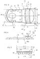
La figure 1 est une vue latérale d'un ski avec ses fixations avant et arrière de retenue de la chaussure ainsi que le dispositif de l'invention.Figure 1 is a side view of a ski with its front bindings and rear retaining shoe and the device of the invention.
La figure 2 est une vue de dessus de la figure 1 sans la chaussure.Figure 2 is a top view of Figure 1 without the shoe.
Les figures 3, 4, 5 et 6 représentent le mode d'exécution préféré du dispositif d'appui selon l'invention.Figures 3, 4, 5 and 6 show the preferred embodiment of the support device according to the invention.
La figure 3 est une vue de dessus.Figure 3 is a top view.
La figure 4 est une vue latérale.Figure 4 is a side view.
La figure 5 est une vue en coupe selon AA de la figure 4.FIG. 5 is a sectional view along AA of FIG. 4.
La figure 6 est une vue en bout avec le ski et la chaussure. Figure 6 is an end view with the ski and the boot.
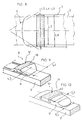
La figure 7 est une vue en perspective.Figure 7 is a perspective view.
La figure 8 est une vue schématique représentant la zone d'appui du dispositif d'appui selon l'invention avec le ski, la semelle de la chaussure et la mâchoire de la butée de retenue de la chaussure.Figure 8 is a schematic view showing the support area of the support device according to the invention with the ski, the sole of the shoe and the jaw of the shoe retaining stop.
Les figures 9 et 10 sont des vues similaires à la figure 6, représentant deux variantes d'exécution.Figures 9 and 10 are views similar to Figure 6, representing two variants of execution.
Les figures 11 et 12 sont des vues schématiques en coupe transversale de deux autres modes d'exécution possibles du supportFigures 11 and 12 are schematic sectional views transverse of two other possible modes of execution of the support
On notera que sur les dessins, la zone d'appui a été illustrée de façon grisée, avec un ensemble de petits points.Note that in the drawings, the support area has been illustrated by grayed out, with a set of small dots.
Comme nous l'avons dit précédemment et comme cela apparaít sur les figures 1 et 2, la chaussure (1) du skieur est retenue sur le ski (2) de façon déclenchable par son extrémité avant (3) grâce à une fixation de sécurité avant (4) appelée communément "butée" et par son extrémité arrière et notamment son talon (5) grâce à une fixation de sécurité arrière (6) appelée "talonnière".As we said before and as it appears in FIGS. 1 and 2, the boot (1) of the skier is retained on the ski (2) of triggered by its front end (3) thanks to a fixing of front safety (4) commonly called "stop" and by its end rear and in particular its heel (5) thanks to a rear safety fastening (6) called "heel piece".
Ajoutons que l'avant de la chaussure (3) est en appui par sa surface inférieure (7) sur le dispositif d'appui (8) de l'invention.Add that the front of the shoe (3) is supported by its lower surface (7) on the support device (8) of the invention.
Le dispositif d'appui (8) selon l'invention, sur lequel est destiné à s'appuyer l'avant de la semelle, est constitué par un support (9) fixé sur la surface supérieure du ski et sur lequel est fixée, par tous moyens, une plaquette antifriction (10).The support device (8) according to the invention, on which is intended to support the front of the sole, is constituted by a support (9) fixed on the upper surface of the ski and on which is fixed, by any means, a anti-friction plate (10).
La pièce support (9) comprend au moins une partie arrière (11) qui comprend la plaquette antifriction (10), et peut comprendre tel que cela est illustré plus particulièrement aux figures 3 et 4, une partie avant (12) engagée sous l'embase (13) de la fixation avant (3). Notons que la pièce support (9) est avantageusement réalisée en matière plastique comme, par exemple, en résine du type acétale, en polypropylène ou en polyamide ou en tout autre matériau et est, par exemple, fixée sur le ski par collage, par des vis ou par sa liaison avec la fixation avant (3) comme, par exemple, avec son embase telle qu'illustrée.The support part (9) comprises at least one rear part (11) which includes the anti-friction plate (10), and can include such that this is illustrated more particularly in FIGS. 3 and 4, a front part (12) engaged under the base (13) of the front fixing (3). Note that the support part (9) is advantageously made of plastic such as, for example, acetal type resin, polypropylene or polyamide or any other material and is, for example, fixed on the ski by gluing, by screws or by its connection with the front fixing (3) like, for example, with its base as illustrated.
Ajoutons que la plaquette antifriction (10) est une plaquette allongée réalisée en matériau de faible coefficient de frottement ou au moins d'un coefficient de frottement plus faible que celui du matériau dont est réalisé le support (9). Ainsi la plaquette antifriction (10) peut être, par exemple, en polytétrafluoréthylène (PTFE) ou en polyéthylène de haute densité, voire en un matériau tel que du polytétrafluoréthylène chargé de billes de bronze, ou tout autre matériau.Add that the anti-friction plate (10) is a plate elongated made of low friction material or less of a lower coefficient of friction than that of the material which the support (9) is made of. Thus the anti-friction plate (10) can be, for example, polytetrafluoroethylene (PTFE) or polyethylene high density, or even a material such as polytetrafluoroethylene loaded with bronze beads, or any other material.
La partie avant (12) du support (9) est constituée par une paroi inférieure (14) bordée latéralement par une paroi périphérique (15) destinée à former avec ladite paroi inférieure (14) une cuvette (16) destinée à recevoir l'embase (13) de la fixation avant (4).The front part (12) of the support (9) is constituted by a wall lower (14) bordered laterally by a peripheral wall (15) intended to form with said bottom wall (14) a bowl (16) intended to receive the base (13) of the front fixing (4).
La partie avant (12) est prolongée vers l'arrière par la partie arrière (11) destinée à recevoir la plaquette antifriction (10).The front part (12) is extended towards the rear by the part rear (11) intended to receive the anti-friction plate (10).
Selon une caractéristique de l'invention, la largeur (L1) de la partie avant (12) du support (9) est avantageusement inférieure ou égale à la largeur (L2) du ski (2), tandis que la largeur de la partie arrière (11) du support (9) est telle que la zone d'appui (17) de l'avant de la semelle de la chaussure a une largeur (L3) plus large que la largeur (L2) qu'a le ski (2) dans la zone correspondante, la mesure de la largeur étant prise transversalement, c'est-à-dire perpendiculairement à l'axe (P) de symétrie générale du ski. Ainsi, la largeur (L3) de la plaquette antifriction qui constitue la zone d'appui (17) est supérieure à la largeur (L2) du ski (2).According to a characteristic of the invention, the width (L1) of the front part (12) of the support (9) is advantageously less than or equal to the width (L2) of the ski (2), while the width of the rear part (11) of the support (9) is such that the support zone (17) of the front of the sole the boot has a width (L3) wider than the width (L2) than the ski (2) in the corresponding zone, the width measurement being taken transversely, i.e. perpendicular to the axis (P) of symmetry general skiing. Thus, the width (L3) of the anti-friction pad which constitutes the support zone (17) is greater than the width (L2) of the ski (2).
Selon le mode d'exécution illustré aux figures 1 à 7, la plaquette antifriction (10) est légèrement encastrée dans le support (9) pour ne dépasser vers le haut que très légèrement. On notera donc que la surface supérieure (18) de la partie arrière (11) du support (9), c'est-à-dire dans la zone d'encastrement, de la plaquette, a une largeur (L4) légèrement plus grande que la largueur (L3) de ladite plaquette antifriction (10). La largeur (L4) de la surface supérieure (18) de la partie arrière (11) où se trouve ladite plaquette est donc plus large que la largeur (L2) du ski.According to the embodiment illustrated in Figures 1 to 7, the plate antifriction (10) is slightly recessed in the support (9) to avoid protrude upward only very slightly. It will therefore be noted that the surface upper (18) of the rear part (11) of the support (9), that is to say in the installation area, of the plate, has a width (L4) slightly more greater than the width (L3) of said anti-friction plate (10). The width (L4) of the upper surface (18) of the rear part (11) where is located said plate is therefore wider than the width (L2) of the ski.
On notera aussi que la partie arrière (11) du support est telle que sa surface inférieure (15) est, au moins dans la zone où se trouve la zone d'appui, plus petite que la largeur (L3) de la plaquette antifriction (10) et que la largeur (L4) de la surface supérieure (18). Aussi, la largeur (L4) de la surface supérieure (18) du support ainsi que la largeur (L3) de la plaquette antifriction (10) sont supérieures à la largeur (L5) de la surface inférieure (15) dudit support. On notera que les bordures latérales (19, 20) du support dans la zone où se situe la zone d'appui (17) sont inclinées pour être convergentes vers le bas.It will also be noted that the rear part (11) of the support is such that its lower surface (15) is, at least in the area where the area is located support, smaller than the width (L3) of the anti-friction plate (10) and than the width (L4) of the upper surface (18). Also, the width (L4) of the upper surface (18) of the support as well as the width (L3) of the plate antifriction (10) are greater than the width (L5) of the lower surface (15) of said support. Note that the lateral borders (19, 20) of the support in the area where the support area (17) is located are inclined to be converging downwards.
Bien entendu, l'invention concerne aussi un dispositif d'appui du type de celui illustré à la figure 9 selon lequel le support (9) ne comprend pas d'éléments antifriction, la chaussure étant directement en appui sur la surface supérieure (18) de la partie arrière (11) du support qui a une largeur (L4), ladite surface supérieure étant alors la zone d'appui (17) pour la chaussure.Of course, the invention also relates to a support device for the type of that illustrated in FIG. 9 according to which the support (9) does not include no anti-friction elements, the shoe being directly supported on the upper surface (18) of the rear part (11) of the support which has a width (L4), said upper surface then being the support zone (17) for the shoe.
Bien entendu, l'invention concerne tout autre type de dispositif d'appui pour l'extrémité avant de la chaussure comme, par exemple, un dispositif d'appui du type de celui décrit dans le dépôt de brevet français n° 96 14339 et comprenant un élément mobile d'appui. Ce type de dispositif est illustré à la figure 10 et comprend un support fixe (9) sur lequel se déplace latéralement un élément mobile d'appui (21). Dans ce mode d'exécution et selon l'invention, la largeur (L7) de la zone d'appui est supérieure à la largeur (L2) du ski. Of course, the invention relates to any other type of device support for the front end of the shoe such as, for example, a support device of the type described in the French patent filing n ° 96 14339 and comprising a movable support element. This kind of device is illustrated in Figure 10 and includes a fixed support (9) on which moves laterally a movable support element (21). In this embodiment and according to the invention, the width (L7) of the support zone is greater than the width (L2) of the ski.
On a compris que la largeur (L3, L4, L7) de la zone d'appui (17) doit être la plus large possible et supérieure à la largeur (L5) de la surface inférieure (15) du support, du moins dans la zone où se situe la zone d'appui (17). Elle est avantageusement comprise entre la largeur (L2) du ski et la largeur (L6) de la semelle dans la zone de son extrémité avant en appui sur le dispositif d'appui. Bien entendu, la largeur (L3, L4, L7) de la zone d'appui (17) peut être supérieure à la largeur (L6) de la semelle, mais la largeur (L3, L4, L7) de la zone d'appui (17) est de préférence égale à la largeur (L6) de la semelle.It has been understood that the width (L3, L4, L7) of the support zone (17) must be as wide as possible and greater than the width (L5) of the surface lower (15) of the support, at least in the area where the area is located support (17). It is advantageously between the width (L2) of the ski and the width (L6) of the sole in the region of its front end in support on the support device. Of course, the width (L3, L4, L7) of the bearing area (17) may be greater than the width (L6) of the sole, but the width (L3, L4, L7) of the support zone (17) is preferably equal to the width (L6) of the sole.
Les figures 11 et 12 sont des vues illustrant d'autres modes d'exécution des bords latéraux (19, 20) de la pièces support. Selon la figure 11, les bords latéraux (19,20) sont concaves tandis que, selon la variante de la figure 12, ceux-ci sont réalisés par une succession de faces. Bien entendu, selon ces deux variantes, la largeur de la surface supérieure (18) du support est supérieure à la largeur (L5) de sa face inférieure (15).Figures 11 and 12 are views illustrating other modes of execution of the lateral edges (19, 20) of the support parts. According to Figure 11, the side edges (19,20) are concave while, according to the variant of Figure 12, these are made by a succession of faces. Of course, according to these two variants, the width of the upper surface (18) of the support is greater than the width (L5) of its lower face (15).
Bien entendu, l'invention n'est pas limitée aux modes de réalisation décrits et représentés à titre d'exemples, mais elle comprend aussi tous les équivalents techniques ainsi que leurs combinaisons.Of course, the invention is not limited to the modes of realization described and represented as examples, but it includes also all technical equivalents and their combinations.
Claims (8)
Applications Claiming Priority (2)
| Application Number | Priority Date | Filing Date | Title |
|---|---|---|---|
| FR0000226 | 2000-01-07 | ||
| FR0000226A FR2803533B1 (en) | 2000-01-07 | 2000-01-07 | SUPPORT DEVICE FOR THE FRONT OF A SKI SHOE ON A SKI |
Publications (2)
| Publication Number | Publication Date |
|---|---|
| EP1114656A1 true EP1114656A1 (en) | 2001-07-11 |
| EP1114656B1 EP1114656B1 (en) | 2002-10-16 |
Family
ID=8845732
Family Applications (1)
| Application Number | Title | Priority Date | Filing Date |
|---|---|---|---|
| EP00410144A Expired - Lifetime EP1114656B1 (en) | 2000-01-07 | 2000-11-27 | Device for supporting the front boot portion on a ski |
Country Status (5)
| Country | Link |
|---|---|
| US (1) | US6637767B2 (en) |
| EP (1) | EP1114656B1 (en) |
| AT (1) | ATE226103T1 (en) |
| DE (1) | DE60000602T2 (en) |
| FR (1) | FR2803533B1 (en) |
Families Citing this family (3)
| Publication number | Priority date | Publication date | Assignee | Title |
|---|---|---|---|---|
| FR2837716B1 (en) * | 2002-03-27 | 2004-05-14 | Rossignol Sa | SUPPORT DEVICE FOR A BINDING ELEMENT AND SNOW SLIDING BOARD THUS EQUIPPED |
| FR2903321B1 (en) * | 2006-07-07 | 2009-01-23 | Salomon Sa | ELEMENT AND RETAINING ASSEMBLY OF A SHOE ON A SLIDING OR ROLLING BOARD |
| FR2955750B1 (en) * | 2010-02-04 | 2012-04-20 | Salomon Sas | IMPROVED SHOE SHOE |
Citations (7)
| Publication number | Priority date | Publication date | Assignee | Title |
|---|---|---|---|---|
| FR2150314A1 (en) | 1971-08-25 | 1973-04-06 | Beyl Jean Joseph Alfred | |
| US4516792A (en) * | 1982-08-13 | 1985-05-14 | Geze Gmbh | Laterally releasable toe unit for a ski safety binding |
| FR2615748A1 (en) * | 1987-05-25 | 1988-12-02 | Plastic Omnium Cie | Bearing piece for a ski binding including a low-friction coating |
| FR2615747A1 (en) | 1987-05-25 | 1988-12-02 | Plastic Omnium Cie | Bearing piece for a ski binding including a low-friction coating |
| US4902031A (en) * | 1987-10-12 | 1990-02-20 | Geze Sport International Gmbh | Toe unit of a safety ski binding |
| FR2687326A1 (en) * | 1992-02-18 | 1993-08-20 | Salomon Sa | DEVICE FOR MODIFYING THE NATURAL DISTRIBUTION OF A SKI ON ITS SLIDING SURFACE, AND SKI EQUIPPED WITH SUCH A DEVICE. |
| FR2755868A1 (en) | 1996-11-18 | 1998-05-22 | Look Fixations Sa | DEVICE FOR SUPPORTING A SKI SHOE ON A SKI |
Family Cites Families (28)
| Publication number | Priority date | Publication date | Assignee | Title |
|---|---|---|---|---|
| CH506300A (en) * | 1969-02-20 | 1971-04-30 | Schmid Hans | ski |
| FR2165747A1 (en) | 1971-12-28 | 1973-08-10 | Rubinstein Inc H | |
| US3854738A (en) * | 1973-05-31 | 1974-12-17 | N Fish | Monoski |
| US3905906A (en) * | 1973-09-18 | 1975-09-16 | James M Edmund | Anti-friction device for safety ski binding |
| US4336956A (en) * | 1979-02-15 | 1982-06-29 | Vereinigte Baubeschlagfabriken Gretsch & Co. Gmbh | Safety toe unit for a ski binding |
| FR2449459A1 (en) * | 1979-02-21 | 1980-09-19 | Salomon & Fils F | SECURITY FIXING FOR SKI |
| FR2471795B1 (en) | 1979-12-21 | 1985-05-31 | Look Sa | SKI ATTACHMENT FRONT |
| FR2524812B1 (en) * | 1982-04-08 | 1986-05-23 | Salomon Sa | SAFETY FIXING DEVICE FOR CROSS-COUNTRY SKIING |
| SE436690B (en) * | 1983-05-20 | 1985-01-21 | Eriksson Karl G V | DEVICE FOR SKI WITH VARIABLE SPAN |
| US4592568A (en) * | 1984-07-23 | 1986-06-03 | Priskich Damir R | Ski boot mounting structure for facilitating monoskiing on snow |
| US4678200A (en) * | 1985-12-20 | 1987-07-07 | William Powell | Platform for attaching to a ski to provide a monoski |
| US4735435A (en) * | 1986-06-05 | 1988-04-05 | Marker Deutschland Gmbh | Front-piece for a safety ski-binding |
| FR2609900B1 (en) * | 1987-01-28 | 1989-05-05 | Salomon Sa | FREE ANTIFRICTION PLATE WITH AUTOMATIC RECENTRENT SLIDER FOR SECURITY FIXING |
| DE3720440A1 (en) * | 1987-06-19 | 1989-01-05 | Geze Sport | SIDE-RELEASABLE FRONT BAKING OF A SAFETY SKI BINDING |
| US5156413A (en) * | 1989-07-26 | 1992-10-20 | Juhasz Paul R | Ski device |
| WO1991008808A1 (en) * | 1989-12-18 | 1991-06-27 | Salomon S.A. | Safety binding for skis |
| DE4008677A1 (en) | 1990-03-17 | 1991-09-19 | Geze Sport | STORAGE DEVICE FOR VERTICAL STABILITY OF A SKI BOOT ON A SKI |
| FR2659865B1 (en) * | 1990-03-26 | 1992-07-24 | Salomon Sa | METHOD FOR ASSEMBLING AN ADD-ON PART AND A SNOW-SLIDING APPARATUS, AND APPARATUS AND ADD-ON SUITABLE FOR THE IMPLEMENTATION OF THIS PROCESS. |
| ATE127701T1 (en) * | 1991-06-17 | 1995-09-15 | Trimble & Co Inc | SKI BINDING CARRYING ELEMENT. |
| FR2678517B1 (en) * | 1991-07-04 | 1993-10-15 | Salomon Sa | IMPROVEMENT FOR SKI DAMPING DEVICE. |
| FR2694206B1 (en) * | 1992-07-31 | 1994-09-02 | Salomon Sa | Safety binding for ski. |
| DE4317675C2 (en) * | 1993-05-27 | 2001-10-25 | Marker Deutschland Gmbh | Support plate for holding a ski boot on a ski |
| FR2712202B1 (en) * | 1993-11-10 | 1995-12-29 | Salomon Sa | Alpine ski binding element. |
| AT404902B (en) * | 1994-01-28 | 1999-03-25 | Varpat Patentverwertung | SUPPORT DEVICE BETWEEN THE SOLE OF A SHOE AND A SPORTS EQUIPMENT |
| FR2718048B1 (en) * | 1994-03-30 | 1996-05-31 | Salomon Sa | Element and assembly for retaining a shoe on a gliding board. |
| FR2722421B1 (en) * | 1994-07-13 | 1996-09-27 | Salomon Sa Societe Anonyme | ALPINE SKI FIXING ELEMENT |
| FR2731161B1 (en) | 1995-03-03 | 1997-05-16 | Salomon Sa | SUPPORT PLATE FOR SKI FIXING ELEMENT |
| US5681054A (en) * | 1995-12-06 | 1997-10-28 | Marker Deutschland Gmbh | Clutch engageable damping and stiffening system |
-
2000
- 2000-01-07 FR FR0000226A patent/FR2803533B1/en not_active Expired - Fee Related
- 2000-11-27 DE DE60000602T patent/DE60000602T2/en not_active Expired - Lifetime
- 2000-11-27 AT AT00410144T patent/ATE226103T1/en not_active IP Right Cessation
- 2000-11-27 EP EP00410144A patent/EP1114656B1/en not_active Expired - Lifetime
-
2001
- 2001-01-05 US US09/755,335 patent/US6637767B2/en not_active Expired - Lifetime
Patent Citations (7)
| Publication number | Priority date | Publication date | Assignee | Title |
|---|---|---|---|---|
| FR2150314A1 (en) | 1971-08-25 | 1973-04-06 | Beyl Jean Joseph Alfred | |
| US4516792A (en) * | 1982-08-13 | 1985-05-14 | Geze Gmbh | Laterally releasable toe unit for a ski safety binding |
| FR2615748A1 (en) * | 1987-05-25 | 1988-12-02 | Plastic Omnium Cie | Bearing piece for a ski binding including a low-friction coating |
| FR2615747A1 (en) | 1987-05-25 | 1988-12-02 | Plastic Omnium Cie | Bearing piece for a ski binding including a low-friction coating |
| US4902031A (en) * | 1987-10-12 | 1990-02-20 | Geze Sport International Gmbh | Toe unit of a safety ski binding |
| FR2687326A1 (en) * | 1992-02-18 | 1993-08-20 | Salomon Sa | DEVICE FOR MODIFYING THE NATURAL DISTRIBUTION OF A SKI ON ITS SLIDING SURFACE, AND SKI EQUIPPED WITH SUCH A DEVICE. |
| FR2755868A1 (en) | 1996-11-18 | 1998-05-22 | Look Fixations Sa | DEVICE FOR SUPPORTING A SKI SHOE ON A SKI |
Also Published As
| Publication number | Publication date |
|---|---|
| DE60000602T2 (en) | 2003-06-26 |
| EP1114656B1 (en) | 2002-10-16 |
| US20010011808A1 (en) | 2001-08-09 |
| US6637767B2 (en) | 2003-10-28 |
| FR2803533A1 (en) | 2001-07-13 |
| ATE226103T1 (en) | 2002-11-15 |
| FR2803533B1 (en) | 2002-04-05 |
| DE60000602D1 (en) | 2002-11-21 |
Similar Documents
| Publication | Publication Date | Title |
|---|---|---|
| CA2146194A1 (en) | Device for binding a shoe to a sliding component | |
| CH619370A5 (en) | ||
| EP0650385A1 (en) | Device for holding a boot on a surfboard | |
| EP0546263B1 (en) | Intermediate tip for the sliding rail of a movable element, particularly for ski bindings | |
| EP0840640A1 (en) | Device for adjusting the position of a binding on a snowboard | |
| CA2332446A1 (en) | Interface device for piece of sports gear | |
| FR2547508A1 (en) | SECURITY FIXING FOR SKI | |
| EP0398794A1 (en) | Adjustable binding device for skiing and skating | |
| FR2807384A1 (en) | AUTOMATIC FIXING DEVICE AND CYCLIST PEDAL PROVIDED WITH SUCH A DEVICE | |
| EP0933100A1 (en) | Shoe retaining device on a snowboard | |
| EP1114656B1 (en) | Device for supporting the front boot portion on a ski | |
| EP1166834A1 (en) | Alpine ski | |
| EP1050325A1 (en) | Device for holding a boot on a snowboard | |
| EP0842678B1 (en) | Support device for a boot on a ski | |
| EP1155716B1 (en) | Device to raise at least a ski binding used on a sliding board | |
| CH673400A5 (en) | ||
| EP0506064A1 (en) | Intermediate plate for alpine security ski binding | |
| EP0778056B1 (en) | Device for retaining a boot on a snowboard, a ski or the like | |
| CH660976A5 (en) | SECURITY FIXING FOR SKIING. | |
| FR2655868A1 (en) | ALPINE SKI SAFETY ATTACHMENT. | |
| FR2502019A1 (en) | SECURITY FIXING FOR SKI | |
| EP2959949B1 (en) | Device for accommodating a shoe on a snow gliding device | |
| EP1025768A1 (en) | Ski boot | |
| FR3130117A1 (en) | ALPINE SKI BOOTS | |
| FR2511602A1 (en) | Ski safety binding with clamp articulated on body - has circular section axle held by extensions of body and centred by piston and spring assembly |
Legal Events
| Date | Code | Title | Description |
|---|---|---|---|
| PUAI | Public reference made under article 153(3) epc to a published international application that has entered the european phase |
Free format text: ORIGINAL CODE: 0009012 |
|
| AK | Designated contracting states |
Kind code of ref document: A1 Designated state(s): AT DE FR |
|
| AX | Request for extension of the european patent |
Free format text: AL;LT;LV;MK;RO;SI |
|
| 17P | Request for examination filed |
Effective date: 20011005 |
|
| GRAG | Despatch of communication of intention to grant |
Free format text: ORIGINAL CODE: EPIDOS AGRA |
|
| GRAG | Despatch of communication of intention to grant |
Free format text: ORIGINAL CODE: EPIDOS AGRA |
|
| GRAH | Despatch of communication of intention to grant a patent |
Free format text: ORIGINAL CODE: EPIDOS IGRA |
|
| 17Q | First examination report despatched |
Effective date: 20020125 |
|
| AKX | Designation fees paid |
Free format text: AT DE FR |
|
| GRAH | Despatch of communication of intention to grant a patent |
Free format text: ORIGINAL CODE: EPIDOS IGRA |
|
| GRAA | (expected) grant |
Free format text: ORIGINAL CODE: 0009210 |
|
| AK | Designated contracting states |
Kind code of ref document: B1 Designated state(s): AT DE FR |
|
| REF | Corresponds to: |
Ref document number: 226103 Country of ref document: AT Date of ref document: 20021115 Kind code of ref document: T |
|
| REF | Corresponds to: |
Ref document number: 60000602 Country of ref document: DE Date of ref document: 20021121 |
|
| PLBE | No opposition filed within time limit |
Free format text: ORIGINAL CODE: 0009261 |
|
| STAA | Information on the status of an ep patent application or granted ep patent |
Free format text: STATUS: NO OPPOSITION FILED WITHIN TIME LIMIT |
|
| 26N | No opposition filed |
Effective date: 20030717 |
|
| PGFP | Annual fee paid to national office [announced via postgrant information from national office to epo] |
Ref country code: AT Payment date: 20081124 Year of fee payment: 9 |
|
| PG25 | Lapsed in a contracting state [announced via postgrant information from national office to epo] |
Ref country code: AT Free format text: LAPSE BECAUSE OF NON-PAYMENT OF DUE FEES Effective date: 20091127 |
|
| PGFP | Annual fee paid to national office [announced via postgrant information from national office to epo] |
Ref country code: DE Payment date: 20131002 Year of fee payment: 14 |
|
| REG | Reference to a national code |
Ref country code: DE Ref legal event code: R119 Ref document number: 60000602 Country of ref document: DE |
|
| PG25 | Lapsed in a contracting state [announced via postgrant information from national office to epo] |
Ref country code: DE Free format text: LAPSE BECAUSE OF NON-PAYMENT OF DUE FEES Effective date: 20150602 |
|
| REG | Reference to a national code |
Ref country code: FR Ref legal event code: PLFP Year of fee payment: 16 |
|
| REG | Reference to a national code |
Ref country code: FR Ref legal event code: PLFP Year of fee payment: 17 |
|
| PGFP | Annual fee paid to national office [announced via postgrant information from national office to epo] |
Ref country code: FR Payment date: 20161129 Year of fee payment: 17 |
|
| REG | Reference to a national code |
Ref country code: FR Ref legal event code: ST Effective date: 20180731 |
|
| PG25 | Lapsed in a contracting state [announced via postgrant information from national office to epo] |
Ref country code: FR Free format text: LAPSE BECAUSE OF NON-PAYMENT OF DUE FEES Effective date: 20171130 |