EP1113847B1 - Procede pour la distillation d'un fluide a transfert horizontal de vapeur dans la zone de condensation et dispositif modulaire de mise en oeuvre du procede - Google Patents
Procede pour la distillation d'un fluide a transfert horizontal de vapeur dans la zone de condensation et dispositif modulaire de mise en oeuvre du procede Download PDFInfo
- Publication number
- EP1113847B1 EP1113847B1 EP99929453A EP99929453A EP1113847B1 EP 1113847 B1 EP1113847 B1 EP 1113847B1 EP 99929453 A EP99929453 A EP 99929453A EP 99929453 A EP99929453 A EP 99929453A EP 1113847 B1 EP1113847 B1 EP 1113847B1
- Authority
- EP
- European Patent Office
- Prior art keywords
- cell
- zone
- condensation
- cells
- evaporation
- Prior art date
- Legal status (The legal status is an assumption and is not a legal conclusion. Google has not performed a legal analysis and makes no representation as to the accuracy of the status listed.)
- Expired - Lifetime
Links
- 238000009833 condensation Methods 0.000 title claims abstract description 54
- 230000005494 condensation Effects 0.000 title claims abstract description 48
- 238000000034 method Methods 0.000 title claims abstract description 26
- 239000012530 fluid Substances 0.000 title claims abstract description 25
- 238000012546 transfer Methods 0.000 title description 4
- 238000001704 evaporation Methods 0.000 claims abstract description 45
- 230000008020 evaporation Effects 0.000 claims abstract description 44
- 239000007788 liquid Substances 0.000 claims abstract description 9
- 238000010438 heat treatment Methods 0.000 claims description 18
- 238000001816 cooling Methods 0.000 claims description 15
- 125000006850 spacer group Chemical group 0.000 claims description 13
- 239000010408 film Substances 0.000 claims description 10
- 239000012141 concentrate Substances 0.000 claims description 5
- 239000010409 thin film Substances 0.000 claims description 5
- 229910052751 metal Inorganic materials 0.000 claims description 4
- 239000002184 metal Substances 0.000 claims description 4
- 238000004891 communication Methods 0.000 claims description 3
- 238000010612 desalination reaction Methods 0.000 claims description 3
- 239000011810 insulating material Substances 0.000 claims description 3
- 239000003643 water by type Substances 0.000 claims description 2
- 230000001737 promoting effect Effects 0.000 claims 1
- 230000003019 stabilising effect Effects 0.000 claims 1
- 230000000694 effects Effects 0.000 abstract description 5
- 239000013535 sea water Substances 0.000 abstract description 5
- 150000003839 salts Chemical class 0.000 abstract description 2
- 238000004821 distillation Methods 0.000 description 14
- XLYOFNOQVPJJNP-UHFFFAOYSA-N water Chemical compound O XLYOFNOQVPJJNP-UHFFFAOYSA-N 0.000 description 12
- 230000008569 process Effects 0.000 description 11
- 239000012528 membrane Substances 0.000 description 9
- 239000002826 coolant Substances 0.000 description 5
- 238000004519 manufacturing process Methods 0.000 description 5
- -1 polypropylene Polymers 0.000 description 5
- 230000009471 action Effects 0.000 description 4
- 238000009434 installation Methods 0.000 description 4
- 239000003507 refrigerant Substances 0.000 description 4
- 238000000909 electrodialysis Methods 0.000 description 3
- 239000013529 heat transfer fluid Substances 0.000 description 3
- 150000002500 ions Chemical class 0.000 description 3
- 238000001223 reverse osmosis Methods 0.000 description 3
- CIWBSHSKHKDKBQ-JLAZNSOCSA-N Ascorbic acid Chemical compound OC[C@H](O)[C@H]1OC(=O)C(O)=C1O CIWBSHSKHKDKBQ-JLAZNSOCSA-N 0.000 description 2
- 239000004743 Polypropylene Substances 0.000 description 2
- RTAQQCXQSZGOHL-UHFFFAOYSA-N Titanium Chemical compound [Ti] RTAQQCXQSZGOHL-UHFFFAOYSA-N 0.000 description 2
- 230000015572 biosynthetic process Effects 0.000 description 2
- 238000010586 diagram Methods 0.000 description 2
- 239000012153 distilled water Substances 0.000 description 2
- 238000005516 engineering process Methods 0.000 description 2
- 150000004677 hydrates Chemical class 0.000 description 2
- 238000007689 inspection Methods 0.000 description 2
- 238000003754 machining Methods 0.000 description 2
- 238000012423 maintenance Methods 0.000 description 2
- 239000004033 plastic Substances 0.000 description 2
- 229920003023 plastic Polymers 0.000 description 2
- 229920001155 polypropylene Polymers 0.000 description 2
- 238000003825 pressing Methods 0.000 description 2
- GUVRBAGPIYLISA-UHFFFAOYSA-N tantalum atom Chemical compound [Ta] GUVRBAGPIYLISA-UHFFFAOYSA-N 0.000 description 2
- 238000003466 welding Methods 0.000 description 2
- 229910001209 Low-carbon steel Inorganic materials 0.000 description 1
- 239000004698 Polyethylene Substances 0.000 description 1
- 230000004888 barrier function Effects 0.000 description 1
- 239000012267 brine Substances 0.000 description 1
- 230000008859 change Effects 0.000 description 1
- 238000004140 cleaning Methods 0.000 description 1
- 230000002328 demineralizing effect Effects 0.000 description 1
- 238000006073 displacement reaction Methods 0.000 description 1
- 230000005684 electric field Effects 0.000 description 1
- 238000000605 extraction Methods 0.000 description 1
- 238000007710 freezing Methods 0.000 description 1
- 230000008014 freezing Effects 0.000 description 1
- 238000005342 ion exchange Methods 0.000 description 1
- 239000000463 material Substances 0.000 description 1
- 230000005012 migration Effects 0.000 description 1
- 238000013508 migration Methods 0.000 description 1
- 238000005457 optimization Methods 0.000 description 1
- 238000005192 partition Methods 0.000 description 1
- 230000000737 periodic effect Effects 0.000 description 1
- 229920000573 polyethylene Polymers 0.000 description 1
- 238000011084 recovery Methods 0.000 description 1
- 239000002990 reinforced plastic Substances 0.000 description 1
- 238000000926 separation method Methods 0.000 description 1
- HPALAKNZSZLMCH-UHFFFAOYSA-M sodium;chloride;hydrate Chemical compound O.[Na+].[Cl-] HPALAKNZSZLMCH-UHFFFAOYSA-M 0.000 description 1
- 239000007787 solid Substances 0.000 description 1
- 238000000638 solvent extraction Methods 0.000 description 1
- 239000003381 stabilizer Substances 0.000 description 1
- 230000000087 stabilizing effect Effects 0.000 description 1
- 239000000126 substance Substances 0.000 description 1
- 229910052715 tantalum Inorganic materials 0.000 description 1
- 239000010936 titanium Substances 0.000 description 1
- 229910052719 titanium Inorganic materials 0.000 description 1
Images

Classifications
-
- F—MECHANICAL ENGINEERING; LIGHTING; HEATING; WEAPONS; BLASTING
- F28—HEAT EXCHANGE IN GENERAL
- F28F—DETAILS OF HEAT-EXCHANGE AND HEAT-TRANSFER APPARATUS, OF GENERAL APPLICATION
- F28F13/00—Arrangements for modifying heat-transfer, e.g. increasing, decreasing
- F28F13/06—Arrangements for modifying heat-transfer, e.g. increasing, decreasing by affecting the pattern of flow of the heat-exchange media
- F28F13/12—Arrangements for modifying heat-transfer, e.g. increasing, decreasing by affecting the pattern of flow of the heat-exchange media by creating turbulence, e.g. by stirring, by increasing the force of circulation
-
- B—PERFORMING OPERATIONS; TRANSPORTING
- B01—PHYSICAL OR CHEMICAL PROCESSES OR APPARATUS IN GENERAL
- B01D—SEPARATION
- B01D1/00—Evaporating
- B01D1/22—Evaporating by bringing a thin layer of the liquid into contact with a heated surface
- B01D1/221—Composite plate evaporators
-
- B—PERFORMING OPERATIONS; TRANSPORTING
- B01—PHYSICAL OR CHEMICAL PROCESSES OR APPARATUS IN GENERAL
- B01D—SEPARATION
- B01D1/00—Evaporating
- B01D1/26—Multiple-effect evaporating
-
- B—PERFORMING OPERATIONS; TRANSPORTING
- B01—PHYSICAL OR CHEMICAL PROCESSES OR APPARATUS IN GENERAL
- B01D—SEPARATION
- B01D1/00—Evaporating
- B01D1/30—Accessories for evaporators ; Constructional details thereof
- B01D1/305—Demister (vapour-liquid separation)
-
- C—CHEMISTRY; METALLURGY
- C02—TREATMENT OF WATER, WASTE WATER, SEWAGE, OR SLUDGE
- C02F—TREATMENT OF WATER, WASTE WATER, SEWAGE, OR SLUDGE
- C02F1/00—Treatment of water, waste water, or sewage
- C02F1/02—Treatment of water, waste water, or sewage by heating
- C02F1/04—Treatment of water, waste water, or sewage by heating by distillation or evaporation
- C02F1/08—Thin film evaporation
-
- F—MECHANICAL ENGINEERING; LIGHTING; HEATING; WEAPONS; BLASTING
- F28—HEAT EXCHANGE IN GENERAL
- F28D—HEAT-EXCHANGE APPARATUS, NOT PROVIDED FOR IN ANOTHER SUBCLASS, IN WHICH THE HEAT-EXCHANGE MEDIA DO NOT COME INTO DIRECT CONTACT
- F28D3/00—Heat-exchange apparatus having stationary conduit assemblies for one heat-exchange medium only, the media being in contact with different sides of the conduit wall, in which the other heat-exchange medium flows in a continuous film, or trickles freely, over the conduits
-
- F—MECHANICAL ENGINEERING; LIGHTING; HEATING; WEAPONS; BLASTING
- F28—HEAT EXCHANGE IN GENERAL
- F28F—DETAILS OF HEAT-EXCHANGE AND HEAT-TRANSFER APPARATUS, OF GENERAL APPLICATION
- F28F3/00—Plate-like or laminated elements; Assemblies of plate-like or laminated elements
- F28F3/08—Elements constructed for building-up into stacks, e.g. capable of being taken apart for cleaning
- F28F3/083—Elements constructed for building-up into stacks, e.g. capable of being taken apart for cleaning capable of being taken apart
-
- F—MECHANICAL ENGINEERING; LIGHTING; HEATING; WEAPONS; BLASTING
- F28—HEAT EXCHANGE IN GENERAL
- F28D—HEAT-EXCHANGE APPARATUS, NOT PROVIDED FOR IN ANOTHER SUBCLASS, IN WHICH THE HEAT-EXCHANGE MEDIA DO NOT COME INTO DIRECT CONTACT
- F28D21/00—Heat-exchange apparatus not covered by any of the groups F28D1/00 - F28D20/00
- F28D2021/0019—Other heat exchangers for particular applications; Heat exchange systems not otherwise provided for
- F28D2021/0061—Other heat exchangers for particular applications; Heat exchange systems not otherwise provided for for phase-change applications
- F28D2021/0066—Other heat exchangers for particular applications; Heat exchange systems not otherwise provided for for phase-change applications with combined condensation and evaporation
-
- Y—GENERAL TAGGING OF NEW TECHNOLOGICAL DEVELOPMENTS; GENERAL TAGGING OF CROSS-SECTIONAL TECHNOLOGIES SPANNING OVER SEVERAL SECTIONS OF THE IPC; TECHNICAL SUBJECTS COVERED BY FORMER USPC CROSS-REFERENCE ART COLLECTIONS [XRACs] AND DIGESTS
- Y02—TECHNOLOGIES OR APPLICATIONS FOR MITIGATION OR ADAPTATION AGAINST CLIMATE CHANGE
- Y02A—TECHNOLOGIES FOR ADAPTATION TO CLIMATE CHANGE
- Y02A20/00—Water conservation; Efficient water supply; Efficient water use
- Y02A20/124—Water desalination
-
- Y—GENERAL TAGGING OF NEW TECHNOLOGICAL DEVELOPMENTS; GENERAL TAGGING OF CROSS-SECTIONAL TECHNOLOGIES SPANNING OVER SEVERAL SECTIONS OF THE IPC; TECHNICAL SUBJECTS COVERED BY FORMER USPC CROSS-REFERENCE ART COLLECTIONS [XRACs] AND DIGESTS
- Y10—TECHNICAL SUBJECTS COVERED BY FORMER USPC
- Y10S—TECHNICAL SUBJECTS COVERED BY FORMER USPC CROSS-REFERENCE ART COLLECTIONS [XRACs] AND DIGESTS
- Y10S159/00—Concentrating evaporators
- Y10S159/08—Multieffect or multistage
-
- Y—GENERAL TAGGING OF NEW TECHNOLOGICAL DEVELOPMENTS; GENERAL TAGGING OF CROSS-SECTIONAL TECHNOLOGIES SPANNING OVER SEVERAL SECTIONS OF THE IPC; TECHNICAL SUBJECTS COVERED BY FORMER USPC CROSS-REFERENCE ART COLLECTIONS [XRACs] AND DIGESTS
- Y10—TECHNICAL SUBJECTS COVERED BY FORMER USPC
- Y10S—TECHNICAL SUBJECTS COVERED BY FORMER USPC CROSS-REFERENCE ART COLLECTIONS [XRACs] AND DIGESTS
- Y10S159/00—Concentrating evaporators
- Y10S159/16—Vacuum
-
- Y—GENERAL TAGGING OF NEW TECHNOLOGICAL DEVELOPMENTS; GENERAL TAGGING OF CROSS-SECTIONAL TECHNOLOGIES SPANNING OVER SEVERAL SECTIONS OF THE IPC; TECHNICAL SUBJECTS COVERED BY FORMER USPC CROSS-REFERENCE ART COLLECTIONS [XRACs] AND DIGESTS
- Y10—TECHNICAL SUBJECTS COVERED BY FORMER USPC
- Y10S—TECHNICAL SUBJECTS COVERED BY FORMER USPC CROSS-REFERENCE ART COLLECTIONS [XRACs] AND DIGESTS
- Y10S159/00—Concentrating evaporators
- Y10S159/28—Porous member
-
- Y—GENERAL TAGGING OF NEW TECHNOLOGICAL DEVELOPMENTS; GENERAL TAGGING OF CROSS-SECTIONAL TECHNOLOGIES SPANNING OVER SEVERAL SECTIONS OF THE IPC; TECHNICAL SUBJECTS COVERED BY FORMER USPC CROSS-REFERENCE ART COLLECTIONS [XRACs] AND DIGESTS
- Y10—TECHNICAL SUBJECTS COVERED BY FORMER USPC
- Y10S—TECHNICAL SUBJECTS COVERED BY FORMER USPC CROSS-REFERENCE ART COLLECTIONS [XRACs] AND DIGESTS
- Y10S203/00—Distillation: processes, separatory
- Y10S203/08—Waste heat
-
- Y—GENERAL TAGGING OF NEW TECHNOLOGICAL DEVELOPMENTS; GENERAL TAGGING OF CROSS-SECTIONAL TECHNOLOGIES SPANNING OVER SEVERAL SECTIONS OF THE IPC; TECHNICAL SUBJECTS COVERED BY FORMER USPC CROSS-REFERENCE ART COLLECTIONS [XRACs] AND DIGESTS
- Y10—TECHNICAL SUBJECTS COVERED BY FORMER USPC
- Y10S—TECHNICAL SUBJECTS COVERED BY FORMER USPC CROSS-REFERENCE ART COLLECTIONS [XRACs] AND DIGESTS
- Y10S203/00—Distillation: processes, separatory
- Y10S203/18—Control
Definitions
- the present invention relates to a structure method and device modular for the distillation of a fluid, applicable in particular but not limited to the desalination of brackish and / or marine waters.
- the technique implemented by the invention enters into the latter category and is based on technologies of dripping film exchangers on multiple effect plates.
- a multi-purpose fast evaporator of this type is for example described in the French patent application FR 2 666 517.
- the cost of the investment is linked for more than 50% to the distiller itself.
- the document EP-A-0046528 describes a process in which the liquid to distilling results in the upper part of an evaporation zone and the vapors produced are transferred through an arranged passage in a partition wall.
- the Applicant has therefore set itself the objective of designing a still completely new structure in order to significantly reduce the cost of an installation.
- the applicant had the idea of designing a modular still which operates on a new process and which results from the assembly of a large number of elementary, simple, available parts commercially or easily mass produced at low cost, even in one country of low technology.
- Anti-crushing means being possibly provided inside the cell if it is kept under vacuum.
- the distributor is defined by an amount transverse drilled with many calibrated holes and fixed in the upper part of the cell between an upright of the spacer frame and the central upright.
- the distributor is formed of a tube drilled with numerous calibrated holes and arranged transversely at the top of the evaporation zone.
- the anti-crushing means is a corrugated mesh with very wide stitches.
- a porous mattress is applied inside the evaporation zone against the central upright and covers the surface with the communication holes.
- the elementary cell comprises a means turbulence promoter and stabilizing dripping film.
- a still film still on multiple effect plates conforming to the invention is characterized in that it consists of at least one cell elementary according to the above characteristics.
- a still according to the invention consists of a set of elementary cells assembled in series thermal, the condensation zone of a cell of order n heating the zone of evaporation of an order cell (n + 1) from the thermal series, the area of the first cell in the series being heated by a heating through an external heat transfer fluid, the condensation zone of the last cell in the series being cooled by a cooling cell crossed by a coolant.
- a distiller can be provided composed of a single cell, the evaporation zone of which is inserted between two heating cells and whose condensation zone is inserted between two cells cooling, the assembly being surrounded by a layer of heat-insulating material.
- all of the cells can be kept in tight contact by threaded tie rods between exterior plates assembly and possibly pressed by pressing means.
- Condensation areas can be kept under vacuum to favor the horizontal transfer of vapors from one zone to another.
- the elementary evaporation-condensation cell (1) as shown schematically by way of nonlimiting example in Figure 1 is a parallelepiped 2 cm thick, contained between two metal plates (2, 3) of two meters high and one meter wide. These plates are separated by a spacer frame (4) made of plastic (for example polypropylene).
- the spacer frame is shared into two identical separate zones, an evaporation zone (EVAP) and a condensation (COND), thanks to a longitudinal central upright (7).
- the evaporation zone (EVAP) of the cell (1) is supplied with the fluid to be distilled through a supply circuit (23) opening into a distributor (8) defined for example in the spacer frame by a transverse upright (9) pierced with numerous calibrated holes (10).
- the fluid to distill trickles in thin film on the two walls of the cell.
- the cell contains a porous lining, for example a corrugated mesh (11) with very large meshes (FIG. 6) intended on the one hand to prevent the crushing of the cells maintained under vacuum, and on the other hand to contribute to the turbulences which improve the heat transfer of the fluid in the process of evaporation.
- Means (6) can also be provided on the walls integrated or not integrated into said walls, ensuring the functions of turbulence promoter and dripping film stabilizer.
- the condensing area of the elementary cell has dimensions identical to the evaporation zone and these two zones communicate at the level of the central upright (7) of the spacer frame by a set of calibrated holes (12) for the passage of the evaporated fluid towards the condensation zone.
- a porous mattress (13) ( Figures 3 and 7) is possibly placed in front of these holes and constitutes a barrier anti-priming to avoid the passage of droplets of the fluid to be distilled in the condenser.
- the excess concentrate or brine is recovered at the bottom of the evaporator via a concentrate circuit (15) and the distilled fluid or distilled water is recovered in the lower part by a distillate circuit (16) ( Figure 2).
- the cells elementary evaporation-condensation are assembled in thermal series, that is to say that the condensation zone of the cells of order (n) heat the zones evaporation of cells of order (n + 1) from the same series of y cells. Only the first and last cells are respectively heated by a fluid external coolant (see coolant duct 14 in Figure 2) and cooled by a refrigerant, such as the fluid to be distilled for example (see conduit refrigerant 15 of Figure 2).
- the heat transfer fluid is for example water vapor and the fluid refrigerant is for example sea water.
- the elementary evaporation-condensation cells are also assembled in x cascades to be assembled in parallel, each cascade comprising y cells assembled in thermal series.
- FIG. 5 shows four waterfalls assembled in parallel.
- Each cascade is made up of five cells in series thermal and begins with a heating cell (18) and ends with a heating cell cooling (19).
- All the heating cells (18) are supplied in parallel by the heat transfer fluid circuit (14) and all the cooling cells (19) are supplied in parallel by the refrigerant circuit (15).
- the y cells in thermal series of a cascade are mounted alternately and according to two parallel assembly planes.
- the heating cell (18) cells C 2 and C 4 , and the cooling cell (19) are adjacent (by contact between the longitudinal uprights of their frames).
- the second assembly plane cells C 1 , C 3 , C 5 are adjacent, by contact between the longitudinal uprights of their frames.
- the condensation zone COND-1 or COND-2 or COND-3 ...
- COND-4) of a cell C n of one of the assembly planes is applied, on the whole of one of its facades against one of the facades of the evaporation zone (EVAP-2 or EVAP-3 or EVAP-4 or EVAP-5) of cell C n + 1 of an assembly plane of the same cascade or of the adjacent waterfall.
- Each condensation zone of a cell of order n (COND-n) thus serving to heat the zone of evaporation of two cells of order n + 1 (EVAP-n + 1) placed on either side.
- the heating (18) and cooling (19) cells have the same thickness than an elementary cell and are half as long, one of their facade is applied against a facade of the evaporation zone (EVAP-1) of a first cell and respectively against one of the facades of the condensation zone (COND-5) of a last cell.
- EVAP-1 evaporation zone
- COND-5 evaporation zone
Landscapes
- Engineering & Computer Science (AREA)
- Chemical & Material Sciences (AREA)
- Mechanical Engineering (AREA)
- Physics & Mathematics (AREA)
- General Engineering & Computer Science (AREA)
- Thermal Sciences (AREA)
- Chemical Kinetics & Catalysis (AREA)
- Life Sciences & Earth Sciences (AREA)
- Hydrology & Water Resources (AREA)
- Environmental & Geological Engineering (AREA)
- Water Supply & Treatment (AREA)
- Organic Chemistry (AREA)
- Vaporization, Distillation, Condensation, Sublimation, And Cold Traps (AREA)
- Polyesters Or Polycarbonates (AREA)
- Physical Or Chemical Processes And Apparatus (AREA)
Description
- les procédés faisant intervenir un changement de phase : la congélation et la distillation,
- les procédés utilisant des membranes : l'osmose inverse et l'électrodialyse,
- les procédés agissant sur les liaisons chimiques à savoir l'échange d'ions, l'extraction par solvants et la formation d'hydrates.
- l'osmose inverse est un procédé de séparation de l'eau et des sels dissous au moyen de membranes sous l'action de la pression. Ce procédé fonctionne à température ambiante.
- l'éléctrodialyse est un procédé qui consiste à déminéraliser les eaux saumâtres et ce, par migration des différents ions à travers des membranes sélectives qui sont soumises à l'action d'un champ électrique. Ce champ résulte de l'application d'une différence de potentiel continue entre deux électrodes délimitant les membranes sélectives précitées.
- le procédé de distillation à détentes étagées est basé sur la distillation, de l'eau de mer préalablement chauffée à une température variant entre 80 et 120° C. Cette distillation résulte des détentes successives de l'eau de mer au sein d'une série de cellules.
- le procédé de distillation à multiples effets est basé sur le principe de l'évaporation sous vide, d'une partie de l'eau de mer préchauffée à une température variant entre 70 et 80° C. Cette évaporalion qui a lieu sur une surface d'échange contrairement à celle dans le procédé précédent où elle est assurée par détentes au sein des cellules, résulte du transfert de chaleur cédée, soit par la condensation de la vapeur (chaleur latente) provenant d'une chaudière, soit par refroidissement d'eau chaude émanant d'un récupérateur de chaleur.
- son volume est délimité par deux plaques métalliques formant les parois de la cellule et maintenues verticalement et séparées par un cadre-espaceur, ledit cadre espaceur étant partagé par un montant central longitudinal en deux zones distinctes sensiblement identiques et communiquant entre-elles, appelées zone d'évaporation et zone de condensation,
- ladite zone d'évaporation étant alimentée en fluide à distiller grâce à un circuit d'alimentation débouchant dans la partie supérieure de la zone d'évaporation, le fluide à distiller ruisselant en film mince sur les deux parois de la cellule,
- le liquide non évaporé ou concentrat en excès étant récupéré en partie basse de la zone d'évaporation par un circuit concentrat,
- le fluide distillé étant récupéré en partie basse de la zone de condensation par un circuit distillat,
- les deux zones d'évaporation et de condensation communiquent entre-elles par un ensemble de trous calibrés prévus dans le montant central.
- il est constitué d'un ensemble de cascades assemblées en parallèle, chaque cascade étant constituée de cellules élémentaires assemblées en alternance en série thermique, selon des plans d'assemblage parallèles, chaque zone de condensation d'une cellule d'ordre n servant ainsi à chauffer la zone d'évaporation de deux cellules d'ordre n + 1 placées de part et d'autre, chaque cascade débutant par une cellule de chauffage et se terminant par une cellule de refroidissement,
- toutes les cellules de chauffage étant alimentées en parallèle par un circuit de fluide caloporteur et toutes les cellules de refroidissement étant alimentées en parallèle par un circuit de fluide frigoporteur.
- les zones d'évaporation et les zones de condensation sont disposées verticalement, et séparées par un montant central longitudinal
- le liquide à distiller débouche en partie haute de la zone d'évaporation, et ruisselle en film mince sur les parois d'une cellule
- les vapeurs produites dans la zone d'évaporation sont transférées horizontalement dans la zone de condensation à travers des trous calibrés du montant central
- le liquide condensé ruisselle verticalement le long des parois de la zone de condensation et s'évacue en partie basse de cette zone.
- la figure 1 est un schéma de principe d'une cellule élémentaire d'évaporation-condensation selon l'invention,
- la figure 2 est un schéma de principe d'un appareil de distillation à multiples effets selon l'invention formé d'une batterie de x cellules selon la figure 1 montées en parallèle et y cellules décalées selon la figure 1 montées en série thermique,
- la figure 3 est une section selon un plan longitudinal d'un premier mode de réalisation de l'invention,
- la figure 4 est une vue en coupe selon un plan AA de la figure 3,
- la figure 5 est une vue en coupe selon un plan BB de la figure 3 correspondant à un distillateur à cinq effets,
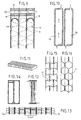
- la figure 6 montre en coupe ct en détail les extrémités supérieures de trois cellules,
- la figure 7 correspond à un distillateur selon l'invention comportant une seule cellule élémentaire,
- la figure 8 est une vue en coupe selon un plan CC de la figure 7,
- la figure 9 est une vue en coupe selon un plan DD de la figure 7,
- la figure 10 montre en coupe verticale les cellules de chauffage et de refroidissement associées à la cellule élémentaire de la figure 7,
- la figure 11 est une vue d'ensemble d'un distillateur modulaire composé de cellules selon l'invention,
- la figure 12 montre en partie une coupe du distillateur de la figure 11 réalisée selon un plan vertical,
- la figure 13 montre des parties d'une coupe du distillateur de la figure 11 réalisée selon un plan horizontal,
- la figure 14 montre en vue de face le type de cadre espaccur utilisé sur le distillateur des figures 12 et 13,
- les figures 15 et 16 montrent des variantes du garnissage poreux interne.
- Sa structure modulaire : elle résulte de l'assemblage d'un très grand nombre de pièces élémentaires, simples, disponibles commercialement ou faciles à fabriquer en grande série à faible coût. Les mêmes pièces élémentaires pourront être utilisées pour constituer des distillateurs ayant des capacités de production variant dans une très large gamme dans un rapport de 1 à 10 000.
- Ces pièces élémentaires sont principalement :
- des tôles planes, de dimensions classiques, sans aucune soudure ni usinage complexe. Elles pourront donc être éventuellement composées de matériaux rares : titane, tantale et même plastiques armées mouillables...
- des cadres-espaceurs de faible épaisseur (par exemple 2 cm), en métal ou en matière plastique (polyéthylène ou polypropylène...), leur forme est variable en fonction des critères d'optimisation ou des contraintes de fabrication,
- des plaques extérieures d'assemblage, avec des tirants filetés (qui pourront être en acier doux, avec usinage très grossier) ou de simples tiges de positionnement, maintenues si nécessaire par des moyens de pressage appropriés.
- des tuyauteries d'alimentation, d'évacuation et de connexions des cellules élémentaires, de dimensions normalisées, également fabriquées en grande série.
- Ces pièces élémentaires seront aisément transportables à faible coût afin d'être assemblées sur place sans aucune soudure, par la main d'oeuvre locale. L'ensemble sera facilement démontable pour inspection et nettoyages périodiques. Pour faciliter le démontage et la maintenance, on peut prévoir un système de déplacement par exemple des rails horizontaux sur lesquels on peut faire coulisser un ensemble de cellules pour intervenir en un plan donné du distillateur.
- Un distillateur, même de très grande capacité, se présentera comme un monobloc massif ne nécessitant aucune charpente coûteuse.
- La manutention, le transport et la mise en oeuvre (assemblage, connexions, etc...) de cellules élémentaires de quelques dizaines de kg n'ont rien de comparable avec ce qui est nécessaire dans les installations existantes pour des éléments de quelques dizaines de tonnes.
Claims (18)
- Procédé de distillation d'un fluide, applicable notamment mais non limitativement au dessalement des eaux saumâtres et/ou marines, du type à films ruisselants sur plaques à multiples effets et comportant une cellule avec une ou plusieurs zones d'évaporation et de zones de condensation, caractérisé en ce que :les zones d'évaporation (EVAP) et les zones de condensation (COND) sont disposées verticalement, et séparées par un montant central longitudinalle liquide à distiller débouche en partie haute de la zone d'évaporation (EVAP), et ruisselle en film mince sur les parois d'une celluleles vapeurs produites dans la zone d'évaporation (EVAP) sont transférées horizontalement dans la zone de condensation (COND) à travers des trous calibrés du montant centralle liquide condensé ruisselle verticalement le long des parois de la zone de condensation et s'évacue en partie basse de cette zone.
- Procédé selon la revendication 1, caractérisé en ce que les zones de condensation sont maintenues en dépression.
- Cellule élémentaire (1) pour la mise en oeuvre du procédé selon l'une des revendications 1 à 2, caractérisée en ce que :son volume est délimité par deux plaques métalliques (2,3) maintenues verticalement et séparées par un cadre-espaceur, ledit cadre espaceur étant partagé par un montant central longitudinal en deux zones distinctes sensiblement identiques et communiquant entre-elles, appelées zone d'évaporation (EVAP) et zone de condensation (COND),ladite zone d'évaporation (EVAP) étant alimentée en fluide à distiller grâce à un circuit d'alimentation (23) débouchant dans la partie supérieure de la zone d'évaporation (EVAP), le fluide à distiller ruisselant en film mince sur les deux parois de la cellule,le liquide non évaporé ou concentrât en excès étant récupéré en partie basse de la zone d'évaporation (EVAP) par un circuit concentrat (15),le fluide distillé étant récupéré en partie basse de la zone de condensation (COND) par un circuit distillat (16),les deux zones d'évaporation et de condensation communiquant entre-elles par un ensemble de trous calibrés (12) prévus dans le montant central (7).
- Cellule élémentaire (1) selon la revendication 3, caractérisée en ce que la cellule est maintenable en dépression.
- Cellule élémentaire (1) selon l'une quelconque des revendications 3 à 4, caractérisée en ce que le circuit d'alimentation débouche par un distributeur (8) défini par un montant transversal (9) percé de nombreux trous calibrés et fixé dans la partie supérieure de la cellule entre un montant du cadre espaceur et le montant central (7).
- Cellule élémentaire (1) selon l'une quelconque des revendications 3 à 4, caractérisée en ce que le circuit d'alimentation débouche par un distributeur (8) formé d'un tube percé de nombreux trous calibrés et disposé transversalement en partie supérieure de la zone d'évaporation.
- Cellule élémentaire (1) selon la revendication 4, caractérisée en ce qu'un moyen anti-écrasement est prévu à l'intérieur de la cellule.
- Cellule élémentaire (1) selon la revendication 7, caractérisée en ce que le moyen anti-écrasement est un grillage ondulé à très larges mailles.
- Cellule élémentaire (1) selon l'une quelconque des revendications 4 à 8, caractérisée en ce qu'elle comporte un matelas poreux (13) appliqué à l'intérieur de la zone d'évaporation contre le montant central et couvrant la surface comportant les trous de communication (12).
- Cellule élémentaire (1) selon l'une quelconque des revendications 2 à 9, caractérisée en ce qu'elle comporte en outre un moyen (6) promoteur de turbulence et stabilisateur de film ruisselant.
- Distillateur à films ruisselants sur plaques à multiples effets, caractérisé en ce qu'il est constitué d'au moins une cellule élémentaire selon l'une des revendications 3 à 10.
- Distillateur selon la revendication 11, caractérisé en ce qu'il est constitué d'un ensemble de y cellules élémentaires assemblées en série thermique, la zone de condensation d'une cellule d'ordre n chauffant la zone d'évaporation d'une cellule d'ordre (n + 1) de la série thermique, la zone d'évaporation de la première cellule de la série étant chauffée par une cellule de chauffage (18) traversée par un fluide caloporteur extérieur, la zone de condensation de la dernière cellule de la série étant refroidie par une cellule de refroidissement (19) traversée par un fluide frigoporteur.
- Distillateur selon la revendication 12, caractérisé en ce que les y cellules élémentaires d'une série thermique sont montées en alternance selon deux plans parallèles.
- Distillateur selon la revendication 11, caractérisé en ce que :il est constitué d'un ensemble de x cascades assemblées en parallèle, chaque cascade étant constituée de y cellules élémentaires assemblées en alternance en série thermique selon des plans d'assemblage parallèles, chaque zone de condensation (CONDn) d'une cellule d'ordre n servant ainsi à chauffer la zone d'évaporation (EVAPn+1) de deux cellules d'ordre n + 1 placées de part et d'autre et chaque cascade débutant par une cellule de chauffage (18) et se terminant par une cellule de refroidissement (19),toutes les cellules de chauffage (18) étant alimentées en parallèle par un circuit de fluide caloporteur (14) et toutes les cellules de refroidissement étant alimentées en parallèle par un circuit de fluide frigoporteur (15).
- Distillateur selon la revendication 11, caractérisé en ce qu'il est composé d'une seule cellule (1), dont la zone d'évaporation (EVAP) est insérée entre deux cellules de chauffage (18) et dont la zone de condensation (COND) est insérée entre deux cellules de refroidissement (19), l'ensemble étant entouré d'une couche de maténau calorifuge (5).
- Distillateur selon l'une des revendications 11 à 15, caractérisé en ce que l'ensemble des cellules est maintenu en contact étanche entre des plaques extérieures d'assemblage.
- Distillateur selon l'une des revendications 11 à 16, caractérisé en ce qu'il est modulaire, c'est-à-dire réalisé uniquement à partir d'un jeu de pièces élémentaires, les mêmes pièces élémentaires pouvant être utilisées pour constituer des distillateurs de capacités différentes prédéterminées.
- Distillateur selon l'une des revendications 11 à 17, caractérisé en ce qu'il comporte en outre un système de déplacement des cellules.
Applications Claiming Priority (3)
| Application Number | Priority Date | Filing Date | Title |
|---|---|---|---|
| FR9809668 | 1998-07-24 | ||
| FR9809668A FR2781387B1 (fr) | 1998-07-24 | 1998-07-24 | Procede pour la distillation d'un fluide a transfert horizontal de vapeur dans la zone de condensation et dispositif modulaire de mise en oeuvre du procede |
| PCT/FR1999/001674 WO2000004968A1 (fr) | 1998-07-24 | 1999-07-09 | Procede pour la distillation d'un fluide a transfert horizontal de vapeur dans la zone de condensation et dispositif modulaire de mise en oeuvre du procede |
Publications (2)
| Publication Number | Publication Date |
|---|---|
| EP1113847A1 EP1113847A1 (fr) | 2001-07-11 |
| EP1113847B1 true EP1113847B1 (fr) | 2002-12-04 |
Family
ID=9529130
Family Applications (1)
| Application Number | Title | Priority Date | Filing Date |
|---|---|---|---|
| EP99929453A Expired - Lifetime EP1113847B1 (fr) | 1998-07-24 | 1999-07-09 | Procede pour la distillation d'un fluide a transfert horizontal de vapeur dans la zone de condensation et dispositif modulaire de mise en oeuvre du procede |
Country Status (9)
| Country | Link |
|---|---|
| US (1) | US6635150B1 (fr) |
| EP (1) | EP1113847B1 (fr) |
| AT (1) | ATE228877T1 (fr) |
| AU (1) | AU4626599A (fr) |
| DE (1) | DE69904348T2 (fr) |
| ES (1) | ES2190224T3 (fr) |
| FR (1) | FR2781387B1 (fr) |
| PT (1) | PT1113847E (fr) |
| WO (1) | WO2000004968A1 (fr) |
Cited By (1)
| Publication number | Priority date | Publication date | Assignee | Title |
|---|---|---|---|---|
| DE102013016626A1 (de) * | 2013-10-08 | 2015-04-09 | Knut Denecke | Vorrichtung und Verfahren zur Aufbereitung von Flüssigkeiten |
Families Citing this family (26)
| Publication number | Priority date | Publication date | Assignee | Title |
|---|---|---|---|---|
| US6861215B1 (en) | 1998-05-21 | 2005-03-01 | Diadexus, Inc. | Method of diagnosing, monitoring, and staging prostate cancer |
| WO2006002636A1 (fr) * | 2004-07-06 | 2006-01-12 | Idekontoret Aps | Couche et module pour systeme de distillation a effet multiple |
| SE528143C2 (sv) * | 2005-01-07 | 2006-09-12 | Alfa Laval Corp Ab | Värmeväxlaranordning |
| RU2280011C1 (ru) * | 2005-05-04 | 2006-07-20 | ЗАО "Московские озонаторы" | Установка для опреснения соленой воды и способ опреснения соленой воды с использованием установки |
| CN100348504C (zh) * | 2005-10-13 | 2007-11-14 | 李保安 | 中空纤维直接接触膜蒸馏脱盐装置及方法 |
| US20070193870A1 (en) * | 2006-02-21 | 2007-08-23 | Prueitt Melvin L | Solar-powered desalination system |
| US20080099324A1 (en) * | 2006-10-26 | 2008-05-01 | Yun-Nan Chiu | Solar energy seawater desalination device |
| DE102008016793A1 (de) * | 2008-04-02 | 2009-10-15 | Institut für Luft- und Kältetechnik gemeinnützige Gesellschaft mbH | Plattenwärmeübertrager |
| US20090288811A1 (en) * | 2008-05-20 | 2009-11-26 | Bolla James D | Aluminum plate-fin heat exchanger utilizing titanium separator plates |
| SG157984A1 (en) * | 2008-06-23 | 2010-01-29 | Univ Singapore | Apparatus and method for improved desalination |
| CN102215927B (zh) * | 2008-09-17 | 2016-06-22 | 纯净源公司 | 大规模水净化和脱盐 |
| AT506691B1 (de) * | 2008-09-23 | 2009-11-15 | Gig Karasek Gmbh | Plattenfallfilm-kurzweg verdampfer |
| DE102009038836A1 (de) | 2009-08-25 | 2011-04-14 | Institut für Luft- und Kältetechnik gemeinnützige Gesellschaft mbH | Plattenwärmeübertrager |
| TWM392171U (en) * | 2010-06-30 | 2010-11-11 | Yeu Ming Tai Chemical Ind Co Ltd | Desalination device |
| US20120055776A1 (en) * | 2010-09-03 | 2012-03-08 | Peter Feher | Multi effect distiller with falling film evaporator and condenser cells |
| EP2680955B1 (fr) * | 2011-03-03 | 2019-10-23 | Victoria University | Système d'échange de chaleur |
| US20120228116A1 (en) * | 2011-03-08 | 2012-09-13 | Environmental Process Solutions Llc | Vacuum Evaporator / Distillation System |
| JP6216716B2 (ja) | 2011-09-09 | 2017-10-18 | シルバン ソース, インコーポレイテッド | 工業的浄水および脱塩 |
| FR2988713A1 (fr) * | 2012-04-03 | 2013-10-04 | Tmw | Distillateur d'eau a courants d'air sature et recuperation optimisee de chaleur latente |
| NL2011454C2 (nl) * | 2013-09-17 | 2015-03-18 | Level Holding Bv | Warmtewisselaar met verbeterde geometrie. |
| US20170144893A1 (en) | 2015-11-25 | 2017-05-25 | Adrian Vazquez Torres | Desalination method by heat and condensation |
| FR3058073A1 (fr) | 2016-11-02 | 2018-05-04 | Commissariat A L'energie Atomique Et Aux Energies Alternatives | Dispositif de precipitation et separation de particules solides dissoutes dans un liquide comprenant un moyen de creation et de maintien de vortex, application au dessalement de l'eau de mer ou de l'eau saumatre |
| US10702794B2 (en) * | 2017-10-30 | 2020-07-07 | The Board Of Regents Of The University Of Oklahoma | Multiple-effect vapor chamber distillation system and methods of use |
| CN116772624B (zh) | 2018-06-07 | 2026-03-03 | 阿法拉伐股份有限公司 | 板式热交换器、热交换板和处理诸如海水的供给物的方法 |
| EP3738657B1 (fr) | 2019-05-16 | 2026-01-28 | Alfa Laval Corporate AB | Échangeur de chaleur à plaques, plaque d'échange de chaleur et procédé de traitement d'un flux tel que de l'eau de mer |
| BE1029506B1 (fr) * | 2021-05-25 | 2023-01-23 | Ind Advanced Services Fze | Echangeur thermique avec extracteurs de vapeur |
Family Cites Families (11)
| Publication number | Priority date | Publication date | Assignee | Title |
|---|---|---|---|---|
| US3788954A (en) * | 1970-06-24 | 1974-01-29 | Petrek J | Interphase mass transfer process from lamina flowing films.005 in.thick |
| US3768539A (en) * | 1971-07-12 | 1973-10-30 | Westinghouse Electric Corp | Modular arrangement of falling film multiple effect evaporator |
| JPS52138743A (en) * | 1976-05-17 | 1977-11-19 | Hisaka Works Ltd | Plate evaporator |
| JPS6049001B2 (ja) * | 1979-05-31 | 1985-10-30 | 住友重機械工業株式会社 | プレ−ト型液膜流下式蒸発缶に於ける循環液飛散防止構造 |
| US4402793A (en) * | 1980-02-19 | 1983-09-06 | Petrek John P | Multiple effect thin film distillation system and process |
| HU179903B (en) * | 1980-08-22 | 1982-12-28 | Laszlo Nadasi | Logic toy |
| FR2609413B1 (fr) * | 1987-01-13 | 1991-01-11 | Inst Francais Du Petrole | Procede d'echange simultane de chaleur et de matiere a travers une paroi poreuse |
| BE1002903A6 (fr) * | 1989-03-13 | 1991-07-23 | Labrique Jean Pierre Adhemar | Installation pour distiller de l'eau avec un courant d'air entrainant la vapeur d'eau. |
| US5133837A (en) | 1990-09-10 | 1992-07-28 | Kamyr, Inc. | Dimpled plate multi-stage flash evaporator |
| US5968321A (en) * | 1996-02-13 | 1999-10-19 | Ridgewood Waterpure Corporation | Vapor compression distillation system and method |
| US5840159A (en) * | 1996-09-30 | 1998-11-24 | Rosenblad; Axel E. | Marine evaporator for fresh water production |
-
1998
- 1998-07-24 FR FR9809668A patent/FR2781387B1/fr not_active Expired - Fee Related
-
1999
- 1999-07-09 US US09/744,354 patent/US6635150B1/en not_active Expired - Fee Related
- 1999-07-09 PT PT99929453T patent/PT1113847E/pt unknown
- 1999-07-09 DE DE69904348T patent/DE69904348T2/de not_active Expired - Fee Related
- 1999-07-09 WO PCT/FR1999/001674 patent/WO2000004968A1/fr not_active Ceased
- 1999-07-09 AU AU46265/99A patent/AU4626599A/en not_active Abandoned
- 1999-07-09 EP EP99929453A patent/EP1113847B1/fr not_active Expired - Lifetime
- 1999-07-09 AT AT99929453T patent/ATE228877T1/de not_active IP Right Cessation
- 1999-07-09 ES ES99929453T patent/ES2190224T3/es not_active Expired - Lifetime
Cited By (2)
| Publication number | Priority date | Publication date | Assignee | Title |
|---|---|---|---|---|
| DE102013016626A1 (de) * | 2013-10-08 | 2015-04-09 | Knut Denecke | Vorrichtung und Verfahren zur Aufbereitung von Flüssigkeiten |
| DE102013016626B4 (de) * | 2013-10-08 | 2017-05-11 | Knut Denecke | Vorrichtung und Verfahren zur Aufbereitung von Flüssigkeiten |
Also Published As
| Publication number | Publication date |
|---|---|
| FR2781387A1 (fr) | 2000-01-28 |
| ATE228877T1 (de) | 2002-12-15 |
| WO2000004968A1 (fr) | 2000-02-03 |
| DE69904348D1 (de) | 2003-01-16 |
| DE69904348T2 (de) | 2003-08-21 |
| PT1113847E (pt) | 2003-04-30 |
| AU4626599A (en) | 2000-02-14 |
| EP1113847A1 (fr) | 2001-07-11 |
| FR2781387B1 (fr) | 2000-09-15 |
| ES2190224T3 (es) | 2003-07-16 |
| US6635150B1 (en) | 2003-10-21 |
Similar Documents
| Publication | Publication Date | Title |
|---|---|---|
| FR2781387A1 (fr) | Procede pour la distillation d'un fluide a transfert horizontal de vapeur dans la zone de condensation et dispositif modulaire de mise en oeuvre du procede | |
| Dang et al. | Ultra salt-resistant solar desalination system via large-scale easy assembly of microstructural units | |
| Andrés-Mañas et al. | Assessment of a pilot system for seawater desalination based on vacuum multi-effect membrane distillation with enhanced heat recovery | |
| Susanto | Towards practical implementations of membrane distillation | |
| US3340186A (en) | Recovery of demineralized water from saline waters | |
| Zaragoza et al. | Efficiency in the use of solar thermal energy of small membrane desalination systems for decentralized water production | |
| US8323491B2 (en) | Combination of a desalination plant and a salinity gradient power reverse electrodialysis plant and use thereof | |
| Hejazi et al. | Effect of intermittent operation on performance of a solar-powered membrane distillation system | |
| US20140299529A1 (en) | Systems, Apparatus, and Methods for Separating Salts from Water | |
| US20040026225A1 (en) | Distillation method and appliances for fresh water production | |
| Roy et al. | The effect of increased top brine temperature on the performance and design of OT-MSF using a case study | |
| WO2013151498A1 (fr) | Système de distillation membranaire à trous d'air sous vide pour la désalinisation | |
| Manzoor et al. | Heat extraction and brine management from salinity gradient solar pond and membrane distillation | |
| FR2855766A1 (fr) | Procedes et appareils de distillation notamment pour produire de l'eau douce | |
| FR2988713A1 (fr) | Distillateur d'eau a courants d'air sature et recuperation optimisee de chaleur latente | |
| FR2475029A1 (fr) | Dessalinisateur d'eau par systeme hydrostatique d'osmose inverse | |
| US8202402B2 (en) | System and method of passive liquid purification | |
| CN107407530A (zh) | 高效脱盐 | |
| Zhang et al. | Thermal distillation of hypersaline waters toward zero liquid discharge via spontaneously siphon-channeling crystallized salt | |
| Yarlagadda et al. | Membrane distillation for desalination and other separations | |
| US20120267231A1 (en) | System and method of passive liquid purification | |
| FR2944277A1 (fr) | Perfectionnements aux distilateurs reproduisant le cycle naturel de l'eau | |
| Tyagi et al. | Model-based zero liquid discharge desalination for land-locked arid/semi-arid regions in India | |
| US20220305442A1 (en) | Heated membrane/module for thermally-driven membrane distillation systems | |
| FR3146814A1 (fr) | Dispositif et procédé pour purifier un fluide en phase liquide |
Legal Events
| Date | Code | Title | Description |
|---|---|---|---|
| PUAI | Public reference made under article 153(3) epc to a published international application that has entered the european phase |
Free format text: ORIGINAL CODE: 0009012 |
|
| 17P | Request for examination filed |
Effective date: 20010112 |
|
| AK | Designated contracting states |
Kind code of ref document: A1 Designated state(s): AT BE CH CY DE DK ES FI FR GB GR IE IT LI LU MC NL PT SE |
|
| GRAG | Despatch of communication of intention to grant |
Free format text: ORIGINAL CODE: EPIDOS AGRA |
|
| GRAG | Despatch of communication of intention to grant |
Free format text: ORIGINAL CODE: EPIDOS AGRA |
|
| GRAH | Despatch of communication of intention to grant a patent |
Free format text: ORIGINAL CODE: EPIDOS IGRA |
|
| 17Q | First examination report despatched |
Effective date: 20020603 |
|
| GRAH | Despatch of communication of intention to grant a patent |
Free format text: ORIGINAL CODE: EPIDOS IGRA |
|
| GRAA | (expected) grant |
Free format text: ORIGINAL CODE: 0009210 |
|
| AK | Designated contracting states |
Kind code of ref document: B1 Designated state(s): AT BE CH CY DE DK ES FI FR GB GR IE IT LI LU MC NL PT SE |
|
| PG25 | Lapsed in a contracting state [announced via postgrant information from national office to epo] |
Ref country code: IE Free format text: LAPSE BECAUSE OF FAILURE TO SUBMIT A TRANSLATION OF THE DESCRIPTION OR TO PAY THE FEE WITHIN THE PRESCRIBED TIME-LIMIT Effective date: 20021204 Ref country code: FI Free format text: LAPSE BECAUSE OF FAILURE TO SUBMIT A TRANSLATION OF THE DESCRIPTION OR TO PAY THE FEE WITHIN THE PRESCRIBED TIME-LIMIT Effective date: 20021204 Ref country code: AT Free format text: LAPSE BECAUSE OF FAILURE TO SUBMIT A TRANSLATION OF THE DESCRIPTION OR TO PAY THE FEE WITHIN THE PRESCRIBED TIME-LIMIT Effective date: 20021204 |
|
| REF | Corresponds to: |
Ref document number: 228877 Country of ref document: AT Date of ref document: 20021215 Kind code of ref document: T |
|
| REG | Reference to a national code |
Ref country code: GB Ref legal event code: FG4D Free format text: NOT ENGLISH |
|
| REG | Reference to a national code |
Ref country code: CH Ref legal event code: EP |
|
| REG | Reference to a national code |
Ref country code: IE Ref legal event code: FG4D Free format text: FRENCH |
|
| REF | Corresponds to: |
Ref document number: 69904348 Country of ref document: DE Date of ref document: 20030116 |
|
| PG25 | Lapsed in a contracting state [announced via postgrant information from national office to epo] |
Ref country code: SE Free format text: LAPSE BECAUSE OF FAILURE TO SUBMIT A TRANSLATION OF THE DESCRIPTION OR TO PAY THE FEE WITHIN THE PRESCRIBED TIME-LIMIT Effective date: 20030304 Ref country code: DK Free format text: LAPSE BECAUSE OF FAILURE TO SUBMIT A TRANSLATION OF THE DESCRIPTION OR TO PAY THE FEE WITHIN THE PRESCRIBED TIME-LIMIT Effective date: 20030304 |
|
| REG | Reference to a national code |
Ref country code: GR Ref legal event code: EP Ref document number: 20030400699 Country of ref document: GR |
|
| GBT | Gb: translation of ep patent filed (gb section 77(6)(a)/1977) |
Effective date: 20030403 |
|
| REG | Reference to a national code |
Ref country code: PT Ref legal event code: SC4A Free format text: AVAILABILITY OF NATIONAL TRANSLATION Effective date: 20030225 |
|
| PG25 | Lapsed in a contracting state [announced via postgrant information from national office to epo] |
Ref country code: LU Free format text: LAPSE BECAUSE OF NON-PAYMENT OF DUE FEES Effective date: 20030709 Ref country code: CY Free format text: LAPSE BECAUSE OF FAILURE TO SUBMIT A TRANSLATION OF THE DESCRIPTION OR TO PAY THE FEE WITHIN THE PRESCRIBED TIME-LIMIT Effective date: 20030709 |
|
| REG | Reference to a national code |
Ref country code: ES Ref legal event code: FG2A Ref document number: 2190224 Country of ref document: ES Kind code of ref document: T3 |
|
| REG | Reference to a national code |
Ref country code: IE Ref legal event code: FD4D Ref document number: 1113847E Country of ref document: IE |
|
| PG25 | Lapsed in a contracting state [announced via postgrant information from national office to epo] |
Ref country code: MC Free format text: LAPSE BECAUSE OF NON-PAYMENT OF DUE FEES Effective date: 20030731 Ref country code: LI Free format text: LAPSE BECAUSE OF NON-PAYMENT OF DUE FEES Effective date: 20030731 Ref country code: CH Free format text: LAPSE BECAUSE OF NON-PAYMENT OF DUE FEES Effective date: 20030731 Ref country code: BE Free format text: LAPSE BECAUSE OF NON-PAYMENT OF DUE FEES Effective date: 20030731 |
|
| PLBE | No opposition filed within time limit |
Free format text: ORIGINAL CODE: 0009261 |
|
| STAA | Information on the status of an ep patent application or granted ep patent |
Free format text: STATUS: NO OPPOSITION FILED WITHIN TIME LIMIT |
|
| 26N | No opposition filed |
Effective date: 20030905 |
|
| BERE | Be: lapsed |
Owner name: CENTRE INTERNATIONAL DE L'EAU DE NANCY *NAN CIE. Effective date: 20030731 |
|
| REG | Reference to a national code |
Ref country code: CH Ref legal event code: PL |
|
| PGFP | Annual fee paid to national office [announced via postgrant information from national office to epo] |
Ref country code: FR Payment date: 20090722 Year of fee payment: 11 Ref country code: ES Payment date: 20090812 Year of fee payment: 11 |
|
| PGFP | Annual fee paid to national office [announced via postgrant information from national office to epo] |
Ref country code: PT Payment date: 20090701 Year of fee payment: 11 Ref country code: NL Payment date: 20090705 Year of fee payment: 11 Ref country code: GR Payment date: 20090619 Year of fee payment: 11 Ref country code: GB Payment date: 20090708 Year of fee payment: 11 Ref country code: DE Payment date: 20090702 Year of fee payment: 11 |
|
| PGFP | Annual fee paid to national office [announced via postgrant information from national office to epo] |
Ref country code: IT Payment date: 20090718 Year of fee payment: 11 |
|
| REG | Reference to a national code |
Ref country code: PT Ref legal event code: MM4A Free format text: LAPSE DUE TO NON-PAYMENT OF FEES Effective date: 20110110 |
|
| REG | Reference to a national code |
Ref country code: NL Ref legal event code: V1 Effective date: 20110201 |
|
| GBPC | Gb: european patent ceased through non-payment of renewal fee |
Effective date: 20100709 |
|
| REG | Reference to a national code |
Ref country code: FR Ref legal event code: ST Effective date: 20110331 |
|
| PG25 | Lapsed in a contracting state [announced via postgrant information from national office to epo] |
Ref country code: DE Free format text: LAPSE BECAUSE OF NON-PAYMENT OF DUE FEES Effective date: 20110201 |
|
| REG | Reference to a national code |
Ref country code: DE Ref legal event code: R119 Ref document number: 69904348 Country of ref document: DE Effective date: 20110201 |
|
| PG25 | Lapsed in a contracting state [announced via postgrant information from national office to epo] |
Ref country code: IT Free format text: LAPSE BECAUSE OF NON-PAYMENT OF DUE FEES Effective date: 20100709 Ref country code: FR Free format text: LAPSE BECAUSE OF NON-PAYMENT OF DUE FEES Effective date: 20100802 Ref country code: NL Free format text: LAPSE BECAUSE OF NON-PAYMENT OF DUE FEES Effective date: 20110201 Ref country code: PT Free format text: LAPSE BECAUSE OF NON-PAYMENT OF DUE FEES Effective date: 20110110 |
|
| PG25 | Lapsed in a contracting state [announced via postgrant information from national office to epo] |
Ref country code: GR Free format text: LAPSE BECAUSE OF NON-PAYMENT OF DUE FEES Effective date: 20110202 |
|
| PG25 | Lapsed in a contracting state [announced via postgrant information from national office to epo] |
Ref country code: GB Free format text: LAPSE BECAUSE OF NON-PAYMENT OF DUE FEES Effective date: 20100709 |
|
| REG | Reference to a national code |
Ref country code: ES Ref legal event code: FD2A Effective date: 20110818 |
|
| PG25 | Lapsed in a contracting state [announced via postgrant information from national office to epo] |
Ref country code: ES Free format text: LAPSE BECAUSE OF NON-PAYMENT OF DUE FEES Effective date: 20100710 |
|
| REG | Reference to a national code |
Ref country code: GR Ref legal event code: ML Ref document number: 20030400699 Country of ref document: GR Effective date: 20110202 |