EP1113571B1 - Modular current sensor and power source - Google Patents
Modular current sensor and power source Download PDFInfo
- Publication number
- EP1113571B1 EP1113571B1 EP00311654A EP00311654A EP1113571B1 EP 1113571 B1 EP1113571 B1 EP 1113571B1 EP 00311654 A EP00311654 A EP 00311654A EP 00311654 A EP00311654 A EP 00311654A EP 1113571 B1 EP1113571 B1 EP 1113571B1
- Authority
- EP
- European Patent Office
- Prior art keywords
- circuit
- current
- power
- current sensor
- output signal
- Prior art date
- Legal status (The legal status is an assumption and is not a legal conclusion. Google has not performed a legal analysis and makes no representation as to the accuracy of the status listed.)
- Expired - Lifetime
Links
Images

Classifications
-
- G—PHYSICS
- G01—MEASURING; TESTING
- G01R—MEASURING ELECTRIC VARIABLES; MEASURING MAGNETIC VARIABLES
- G01R19/00—Arrangements for measuring currents or voltages or for indicating presence or sign thereof
- G01R19/0092—Measuring current only
-
- H—ELECTRICITY
- H02—GENERATION; CONVERSION OR DISTRIBUTION OF ELECTRIC POWER
- H02M—APPARATUS FOR CONVERSION BETWEEN AC AND AC, BETWEEN AC AND DC, OR BETWEEN DC AND DC, AND FOR USE WITH MAINS OR SIMILAR POWER SUPPLY SYSTEMS; CONVERSION OF DC OR AC INPUT POWER INTO SURGE OUTPUT POWER; CONTROL OR REGULATION THEREOF
- H02M1/00—Details of apparatus for conversion
- H02M1/0003—Details of control, feedback or regulation circuits
- H02M1/0009—Devices or circuits for detecting current in a converter
Definitions
- This invention relates to current sensors for duplicating the function of a current transformer, and more particularly, to a modular current sensor and power source.
- Current transformers are used to perform various functions in electrical circuits.
- Current transformers may be disposed on a primary electrical circuit to provide variable electrical power to a secondary electrical circuit.
- Current transformers may also be used as a sensor to sense electrical current in a primary electrical circuit and provide a signal indicative of the magnitude of the current to a secondary electrical circuit. In some applications, a single current transformer is used to perform both of these functions.
- iron core current transformers designed for wide dynamic range require large, heavy and costly iron cores and copper conductors.
- the accuracy and linearity of iron core current transformers is inherently limited by saturation and magnetic losses. As a result, conventional iron core current transformers tend to be expensive, with somewhat limited accuracy.
- a current sensor and power source circuit having a power source, a power supply circuit and a current sensor circuit has become known from US 5 726 846.
- One application where a single current transformer may be used to provide both operating power and a current signal to a secondary circuit is in an electrical circuit breaker having an electronic trip unit.
- Electronic trip units are employed in industrial-rated circuit breakers for a wide variety of protection and other accessory functions.
- One such electronic trip unit is described in U.S. Patent No. 4,672,501 entitled Circuit Breaker and Protective Relay Unit.
- An advantage of using a single current transformer to perform both power and sensing functions is the simplicity of a two-wire connection between the current transformers and the sensing circuitry (e.g. the trip unit).
- the sensing circuitry receives the sensing signal and power from two wires.
- One example of an efficient current transformer used for both sensing and power functions is described in U.S. Patent No. 4,591,942 entitled Current Sensing Transformer Assembly.
- sensing devices such as an air core current transformer, Hall effect device and the like are employed for the current sensing function
- four wires have been required, two for providing power from the power transformer to the power supply circuitry and two for providing signals from the sensing device to the sensing circuitry.
- the added wires can increase the cost to manufacture new devices.
- the need for additional wires precludes using such current sensors with existing applications having a two conductor input.
- a modular current sensor and power source unit are combined in a configuration duplicating the function of a current transformer.
- the invention consists of a sensing circuit, a power source, a power supply, and a current source combined and connected to an electrical distribution circuit and electrical device.
- a current transformer is used as the power source.
- a power supply circuit connects with the current transformer for regulating the operational current input.
- a current sensor circuit is arranged for connection with the electrical distribution circuit for providing a signal indicative of current flow through the electrical distribution circuit.
- a current source circuit connects with the current sensor circuit for receiving the current signal and with the power supply circuit for receiving the operational current from the power supply circuit.
- the current source circuit connects with an electrical device for providing the operational current and the current signal to the electrical device.
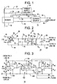
- Modular current sensor and power source unit 10 is disposed on an electrical conductor, such as a phase 11 of an electrical circuit to provide variable electrical power to a load circuit (electrical device) via lines 34 and 36.
- Modular current sensor and power source unit 10 also senses electrical current in phase 11 and provides a signal indicative of the magnitude of the current in phase 11 to the load circuit via lines 34 and 36.
- Modular current sensor and power source unit 10 thus can be used to replace a conventional current transformer (not shown) to provide both operating power and a current signal to the load circuit via two lines 34 and 36.
- Modular current sensor and power source unit 10 includes a current transformer 12, a power supply circuit 14, a current sensor 16, and current source circuit 18.
- current transformer 12 is disposed about one phase 11 of an electrical distribution circuit.
- Current transformer 12 is electrically connected to power supply circuit 14 via lines 22, 24, and power supply circuit 14 is electrically connected to current sensor 16 and current source circuit 18 via lines 26-29.
- Current sensor 16 is disposed about phase 11.
- Current sensor 16 is electrically connected to current source circuit 18 via lines 30, 32.
- Current source circuit 18 is electrically connected to the load circuit via lines 34, 36.
- Current sensor 16 may include, for example, an air core transformer, Hall effect device or a giant magnetoresistive (GMR) device.
- GMR giant magnetoresistive
- current transformer 12 provides operating power to power supply circuit 14 via lines 22 and 24.
- Power supply circuit 14 regulates this operating power and provides the regulated operating power to sensor 16 and current source 18 via lines 26-29.
- Sensor 16 senses current in phase 11 and provides a current sensor output signal indicative of the current in phase 11 to current source 18 via lines 30 and 32.
- Current source 18 receives the current sensor output signal and drives a current source circuit output signal, which is an output current indicative of the current sensor output signal, to the load circuit via lines 34 and 36.
- the source circuit output signal has the attributes of the low power sensor and the ability to provide power to the load circuit.
- sensor 16 is not required to provide operating power to current source 18 or to the load circuit, sensor 16 can comprise any of a number of higher performance current sensing devices such as, for example, an air core transformer, Hall effect device or GMR device.
- transformer 12 is not required to provide a sensed signal to the load circuit, transformer 12 can be optimised for providing power.
- FIG. 2 is a circuit diagram of power supply circuit 14.
- Power supply circuit 14 is a voltage regulated, full wave bridge rectifier with a simple capacitor filter.
- Current from the current transformer 12 provides the input to a full wave bridge rectifier 50 including bridge diodes 52 comprising diodes D1, D2, D3, and D4.
- the full wave bridge rectifier 50 creates a power supply negative power rail on a line 54 and an unfiltered and unregulated positive output voltage on a line 56.
- Diode D5 connected in series between the unfiltered output voltage on line 56 and the regulated output voltage on line 60 prevents current flow from capacitor C1 58 back to the regulator transistor 72.
- a filter section 58 for reducing the ripple of the unfiltered output voltage on line 56 is represented by the capacitor C1 connected between positive power rail 60 and negative power rail 54, creating a filtered output voltage on positive power rail 60.
- a regulator section 62 assures the filtered output voltage provides a constant voltage level to sensor 16 and current source 18 on positive power rail line 60.
- Resistor R2 and zener diode D6 are connected in series between the positive and negative voltage rails 60 and 54, respectively. These provide a reference voltage on a line 66 that is connected to a negative input terminal of a comparator 68.
- a voltage divider comprising resistors R3 and R4 connected in series is connected between the positive and negative voltage rails 60 and 54, respectively.
- the voltage divider provides a sample output voltage on a line 64 that fluctuates with the voltage level on the positive output rail 60.
- the sample output voltage on line 64 is connected to a positive input terminal of comparator 68.
- Comparator 68 generates a logic signal 70 which indicates whether the positive output rail 60 is above or below the desired regulated voltage.
- a source and drain of a field effect transistor (FET) 72 are connected to unfiltered voltage on line 56 and negative voltage rail 54 respectively.
- the logic signal 70 drives the gate of FET 72 thereby shunting current through the FET 72 when the positive output rail is above the desired voltage and thus regulating the output voltage on line 60.
- FET field effect transistor
- Current source circuit 18 includes a voltage amplifier stage 100 and bridge type current source formed from operational amplifiers 102 and 104.
- the voltage amplifier 100 is comprised of an input from the current sensor 16 on line 30 connected to a resistor R7 that is thence connected to the inverting input of an operational amplifier 100.
- Feedback resistor R8 connects an output of op-amp 100 on a line 106 and to the inverting input of op-amp 100.
- a voltage divider 110 formed from series connected resistors R5 and R6 arranged between the positive and negative rails 60, 54 of voltage supply circuit 14, provides a DC voltage at the connection of R5 to R6 on a line 74, which is applied to the non-inverting input of op-amp 100.
- the output of op-amp 100 on line 106 is provided to operational amplifier 102, via a resistor R9 connected to the inverting input of an op-amp 102 configured as a current source.
- Feedback resistor R10 connects an output of op-amp 102 on a line 114 to the inverting input of op-amp 102.
- the output of op-amp 102 on line 114 is connected to a resistor R13, which is connected to line 36.
- a resistor R12 is connected to line 36 and to the non-inverting input of op-amp 102.
- a second resistor R11 connects the non inverting terminal of operational amplifier 102 to the negative power supply rail 108.
- a third operational amplifier, 104 is connected as a unity gain inverter and provides a signal of opposite polarity to that provided by the second operational amplifier, 102.
- Resistors R14 connected between the inverting input and output of the third operational amplifier 104 and R15 connected between the output of the second operational amplifier 102 and the inverting input of the third operational amplifier 104 set the gain of inverting operational amplifier 104.
- Resistors R16 and R17 connected between the positive terminal of the power supply 60, and the negative terminal of the power supply, 54 and the non inverting input of operational amplifier 104 set the bias point of operational amplifier 104.
- Lines 34 and 36 provide a current output to the load circuit, the current output having the attributes of the sensor 16 input on lines 30, 32 and with sufficient power to drive the load circuit.
- FIG 4 is a diagrammatic representation of a circuit breaker trip unit 150 employing a plurality of modular current sensor and power source units 10 of the present invention.
- Circuit breaker trip unit 150 is similar to that described in the aforementioned U.S. Patent No. 4,672,501, which is incorporated by reference.
- each modular current sensor and power source unit 10 is disposed about a phase 152, 154, 156 of a multiphase power distribution circuit.
- Each modular current sensor and power source unit 10 is independently connected to the circuit breaker trip unit 150 via two conductors 34 and 36.
- Each modular current sensor and power source unit 10 provides operating power to circuit breaker trip unit 150 via lines 34 and 36.
- each modular current sensor and power source are effectively combined internally in the circuit breaker trip unit 150 such that each can power the circuit breaker independently.
- Each modular current sensor and power source unit 10 also provides a current signal indicative of the current in its associated phase 152, 154, or 156 via lines 34 and 36.
- the current signals from each modular current sensor and power source are maintained separately for each phase internally in the circuit breaker trip unit 150.
- trip unit 150 detects overcurrent conditions in phases 152, 154, and 156 in a manner described in aforementioned U.S. Patent No. 4,672,501. Because each modular current sensor and power source unit 10 requires only two lines 34 and 36 for connection with electronic trip unit 150, modular current sensor and power source units 10 can be used to replace current transformers used in conjunction with such trip units.
- Modular sensing and power source unit 10 provides the attributes of a highly accurate current sensor while providing operating power to a load circuit without requiring additional wires to be added between the unit and the load source. Thus, modular sensing and power source unit 10 can be used as a replacement for existing current transformers, without having to modify the associated load circuit.
Landscapes
- Physics & Mathematics (AREA)
- General Physics & Mathematics (AREA)
- Measurement Of Current Or Voltage (AREA)
- Measuring Instrument Details And Bridges, And Automatic Balancing Devices (AREA)
- Emergency Protection Circuit Devices (AREA)
- Control Of Voltage And Current In General (AREA)
- Electronic Switches (AREA)
Applications Claiming Priority (2)
| Application Number | Priority Date | Filing Date | Title |
|---|---|---|---|
| US475617 | 1999-12-30 | ||
| US09/475,617 US6433981B1 (en) | 1999-12-30 | 1999-12-30 | Modular current sensor and power source |
Publications (3)
| Publication Number | Publication Date |
|---|---|
| EP1113571A2 EP1113571A2 (en) | 2001-07-04 |
| EP1113571A3 EP1113571A3 (en) | 2002-01-09 |
| EP1113571B1 true EP1113571B1 (en) | 2004-03-17 |
Family
ID=23888382
Family Applications (1)
| Application Number | Title | Priority Date | Filing Date |
|---|---|---|---|
| EP00311654A Expired - Lifetime EP1113571B1 (en) | 1999-12-30 | 2000-12-22 | Modular current sensor and power source |
Country Status (6)
| Country | Link |
|---|---|
| US (1) | US6433981B1 (https=) |
| EP (1) | EP1113571B1 (https=) |
| JP (1) | JP2001359234A (https=) |
| DE (1) | DE60009025T2 (https=) |
| MX (1) | MXPA00012698A (https=) |
| SG (1) | SG102607A1 (https=) |
Families Citing this family (49)
| Publication number | Priority date | Publication date | Assignee | Title |
|---|---|---|---|---|
| US7259545B2 (en) * | 2003-02-11 | 2007-08-21 | Allegro Microsystems, Inc. | Integrated sensor |
| US7174261B2 (en) * | 2003-03-19 | 2007-02-06 | Power Measurement Ltd. | Power line sensors and systems incorporating same |
| US7262943B2 (en) * | 2003-09-15 | 2007-08-28 | General Electric Company | Configuration unit and methods for configuring centrally controlled power distribution systems |
| US7304586B2 (en) | 2004-10-20 | 2007-12-04 | Electro Industries / Gauge Tech | On-line web accessed energy meter |
| US9080894B2 (en) | 2004-10-20 | 2015-07-14 | Electro Industries/Gauge Tech | Intelligent electronic device for receiving and sending data at high speeds over a network |
| US7747733B2 (en) | 2004-10-25 | 2010-06-29 | Electro Industries/Gauge Tech | Power meter having multiple ethernet ports |
| US7557563B2 (en) * | 2005-01-19 | 2009-07-07 | Power Measurement Ltd. | Current sensor assembly |
| US8930153B2 (en) | 2005-01-27 | 2015-01-06 | Electro Industries/Gauge Tech | Metering device with control functionality and method thereof |
| US8190381B2 (en) | 2005-01-27 | 2012-05-29 | Electro Industries/Gauge Tech | Intelligent electronic device with enhanced power quality monitoring and communications capabilities |
| US8160824B2 (en) | 2005-01-27 | 2012-04-17 | Electro Industries/Gauge Tech | Intelligent electronic device with enhanced power quality monitoring and communication capabilities |
| US8620608B2 (en) | 2005-01-27 | 2013-12-31 | Electro Industries/Gauge Tech | Intelligent electronic device and method thereof |
| EP1851780A1 (en) * | 2005-02-18 | 2007-11-07 | Airpax Corporation, LLC | Apparatus comprising circuit breaker with adjunct sensor unit |
| US7768083B2 (en) * | 2006-01-20 | 2010-08-03 | Allegro Microsystems, Inc. | Arrangements for an integrated sensor |
| JP4577781B2 (ja) * | 2006-03-03 | 2010-11-10 | 株式会社リコー | 電源装置および画像形成装置 |
| US7920976B2 (en) | 2007-03-27 | 2011-04-05 | Electro Industries / Gauge Tech. | Averaging in an intelligent electronic device |
| US9989618B2 (en) | 2007-04-03 | 2018-06-05 | Electro Industries/Gaugetech | Intelligent electronic device with constant calibration capabilities for high accuracy measurements |
| US11307227B2 (en) | 2007-04-03 | 2022-04-19 | Electro Industries/Gauge Tech | High speed digital transient waveform detection system and method for use in an intelligent electronic device |
| US10845399B2 (en) | 2007-04-03 | 2020-11-24 | Electro Industries/Gaugetech | System and method for performing data transfers in an intelligent electronic device |
| US20130275066A1 (en) | 2007-04-03 | 2013-10-17 | Electro Industries/Gaugetech | Digital power metering system |
| US8269482B2 (en) * | 2007-09-19 | 2012-09-18 | Electro Industries/Gauge Tech | Intelligent electronic device having circuitry for reducing the burden on current transformers |
| US8269491B2 (en) | 2008-02-27 | 2012-09-18 | Allegro Microsystems, Inc. | DC offset removal for a magnetic field sensor |
| US12061218B2 (en) | 2008-03-13 | 2024-08-13 | Ei Electronics Llc | System and method for multi-rate concurrent waveform capture and storage for power quality metering |
| US8797202B2 (en) | 2008-03-13 | 2014-08-05 | Electro Industries/Gauge Tech | Intelligent electronic device having circuitry for highly accurate voltage sensing |
| US7816905B2 (en) * | 2008-06-02 | 2010-10-19 | Allegro Microsystems, Inc. | Arrangements for a current sensing circuit and integrated current sensor |
| WO2010012301A1 (en) * | 2008-07-30 | 2010-02-04 | Abb Research Ltd | Generator circuit breaker with fiber-optic current sensor |
| KR20110050437A (ko) * | 2008-07-30 | 2011-05-13 | 에이비비 리써치 리미티드 | 광섬유 전류 센서를 갖는 고전압 ac/dc 또는 dc/ac 변환기 스테이션 |
| US7973527B2 (en) | 2008-07-31 | 2011-07-05 | Allegro Microsystems, Inc. | Electronic circuit configured to reset a magnetoresistance element |
| US8063634B2 (en) * | 2008-07-31 | 2011-11-22 | Allegro Microsystems, Inc. | Electronic circuit and method for resetting a magnetoresistance element |
| US9678114B2 (en) | 2009-04-16 | 2017-06-13 | Panoramic Power Ltd. | Apparatus and methods thereof for error correction in split core current transformers |
| US9134348B2 (en) | 2009-04-16 | 2015-09-15 | Panoramic Power Ltd. | Distributed electricity metering system |
| CN102460188B (zh) | 2009-04-16 | 2015-09-16 | 全景电力有限公司 | 用于在断路器点的功率消耗测量的设备和方法 |
| US20120029718A1 (en) * | 2010-05-21 | 2012-02-02 | Davis Edward L | Systems and methods for generating and utilizing electrical signatures for electrical and electronic equipment |
| CN103748477B (zh) * | 2011-08-18 | 2016-03-16 | 西门子公司 | 用于设备组成部分的状态监控的装置和方法 |
| US20130294014A1 (en) * | 2012-05-02 | 2013-11-07 | Server Technology, Inc. | Relay with integrated power sensor |
| CN105074480A (zh) * | 2013-02-21 | 2015-11-18 | 泰拉能源系统解决方案有限公司 | 在线路上以并联的方式分设有检测用电流互感器和发电用电流互感器的电流变换系统及通过无线通信网对其进行管理的集成系统 |
| DE102013103350A1 (de) * | 2013-04-04 | 2014-10-09 | Weidmüller Interface GmbH & Co. KG | Stromwandler und Verfahren zum Wandeln eines in einem elektrischen Leiter fließenden Leiterstroms in ein Ausgangssignal |
| DE102013107088A1 (de) * | 2013-07-05 | 2015-01-08 | Endress + Hauser Gmbh + Co. Kg | Schaltungsanordnung zum Schutz von mindestens einem Bauteil eines Zweidrahtstromkreises |
| US9354284B2 (en) | 2014-05-07 | 2016-05-31 | Allegro Microsystems, Llc | Magnetic field sensor configured to measure a magnetic field in a closed loop manner |
| US9322887B1 (en) | 2014-12-01 | 2016-04-26 | Allegro Microsystems, Llc | Magnetic field sensor with magnetoresistance elements and conductive-trace magnetic source |
| US9891252B2 (en) | 2015-07-28 | 2018-02-13 | Panoramic Power Ltd. | Thermal management of self-powered power sensors |
| US10024885B2 (en) | 2015-07-28 | 2018-07-17 | Panoramic Power Ltd. | Thermal management of self-powered power sensors |
| MX2020000895A (es) | 2017-07-26 | 2020-07-22 | Panoramic Power Ltd | Sincronización temporal de sensores de potencia autoalimentados y un controlador central que recoge muestras de los mismos. |
| WO2019022796A1 (en) | 2017-07-26 | 2019-01-31 | Panoramic Power Ltd. | SYSTEM AND METHOD FOR TIME SYNCHRONIZATION OF SELF-POWERED POWER SENSOR |
| US10436825B2 (en) | 2017-07-26 | 2019-10-08 | Panoramic Power Ltd. | System and method for transmission of time stamps of current samples sampled by a self-powered power sensor |
| US10763055B2 (en) * | 2017-09-01 | 2020-09-01 | Te Connectivity Corporation | Pin configurable smart current sensor |
| US10935612B2 (en) | 2018-08-20 | 2021-03-02 | Allegro Microsystems, Llc | Current sensor having multiple sensitivity ranges |
| US10958062B2 (en) * | 2018-11-13 | 2021-03-23 | Rockwell Automation Technologies, Inc. | Systems and methods for dynamically switching a load of a current transformer circuit |
| US11567108B2 (en) | 2021-03-31 | 2023-01-31 | Allegro Microsystems, Llc | Multi-gain channels for multi-range sensor |
| US11994541B2 (en) | 2022-04-15 | 2024-05-28 | Allegro Microsystems, Llc | Current sensor assemblies for low currents |
Family Cites Families (13)
| Publication number | Priority date | Publication date | Assignee | Title |
|---|---|---|---|---|
| US4672501A (en) | 1984-06-29 | 1987-06-09 | General Electric Company | Circuit breaker and protective relay unit |
| DE3441403A1 (de) | 1984-11-13 | 1986-05-22 | Rheinmetall GmbH, 4000 Düsseldorf | Schaltungsanordnung zum schalten ohmscher und induktiver elektrischer verbraucher in gleich- und wechselstromkreisen |
| US4591942A (en) | 1984-12-07 | 1986-05-27 | General Electric Company | Current sensing transformer assembly |
| FR2626724B1 (fr) * | 1988-01-28 | 1993-02-12 | Merlin Gerin | Declencheur statique comportant un circuit de declenchement instantane independant de la tension d'alimentation |
| US4992723A (en) * | 1989-03-31 | 1991-02-12 | Square D Company | Fault-powered power supply |
| EP0416422B1 (de) | 1989-09-07 | 1994-05-25 | Siemens Aktiengesellschaft | Differenzstromschutzschalter |
| ES2133336T3 (es) | 1993-03-04 | 1999-09-16 | Cit Alcatel | Regulador de derivacion de fuente de alimentacion. |
| FR2725320B1 (fr) | 1994-09-29 | 1996-10-31 | Schneider Electric Sa | Dispositif de declenchement comportant au moins un transformateur de courant |
| US5583732A (en) | 1994-12-19 | 1996-12-10 | General Electric Company | Modular current transformer for electronic circuit interrupters |
| US5615075A (en) | 1995-05-30 | 1997-03-25 | General Electric Company | AC/DC current sensor for a circuit breaker |
| US5892420A (en) * | 1996-08-28 | 1999-04-06 | General Electric Company | Electronic circuit breaker having modular current transformer sensors |
| US6141197A (en) * | 1998-03-10 | 2000-10-31 | General Electric Company | Smart residential circuit breaker |
| US5959819A (en) * | 1998-03-16 | 1999-09-28 | Eaton Corporation | Reliable fault tolerant power supply for a protective relay |
-
1999
- 1999-12-30 US US09/475,617 patent/US6433981B1/en not_active Expired - Fee Related
-
2000
- 2000-12-18 MX MXPA00012698A patent/MXPA00012698A/es active IP Right Grant
- 2000-12-20 SG SG200007534A patent/SG102607A1/en unknown
- 2000-12-22 DE DE2000609025 patent/DE60009025T2/de not_active Expired - Lifetime
- 2000-12-22 EP EP00311654A patent/EP1113571B1/en not_active Expired - Lifetime
- 2000-12-28 JP JP2000399779A patent/JP2001359234A/ja not_active Ceased
Also Published As
| Publication number | Publication date |
|---|---|
| MXPA00012698A (es) | 2003-06-04 |
| US6433981B1 (en) | 2002-08-13 |
| JP2001359234A (ja) | 2001-12-26 |
| EP1113571A2 (en) | 2001-07-04 |
| DE60009025T2 (de) | 2004-11-18 |
| DE60009025D1 (de) | 2004-04-22 |
| SG102607A1 (en) | 2004-03-26 |
| EP1113571A3 (en) | 2002-01-09 |
Similar Documents
| Publication | Publication Date | Title |
|---|---|---|
| EP1113571B1 (en) | Modular current sensor and power source | |
| JP4149915B2 (ja) | 絶縁切替え調整器におけるインダクタ電流感知および関連する方法 | |
| US7190215B2 (en) | Method and apparatus for sensing current and voltage in circuits with voltage across an LED | |
| US5534768A (en) | Regulated power supply having wide input AC/DC voltage range | |
| CA1218409A (en) | Pulse width modulated inverter for unbalanced and variable power factor loads | |
| US4502106A (en) | Current source sine wave inverter | |
| US5982136A (en) | Circuit for sensing current in power trains for motor control | |
| US4218647A (en) | Voltage regulator with current limiting circuitry | |
| WO1994005067A9 (en) | Active filter for reducing non-fundamental currents and voltages | |
| EP0609434A1 (en) | Active filter for reducing non-fundamental currents and voltages | |
| US5363323A (en) | Power supply with plural outputs supplying dynamic and steady loads | |
| US5610532A (en) | Isolated DC fault current sensor | |
| US8466668B2 (en) | Transient differential switching regulator | |
| US5243489A (en) | Protection circuit for multiple phase power system | |
| JPH0630579A (ja) | 電流検出回路 | |
| RU2100837C1 (ru) | Стабилизатор переменного напряжения | |
| US20030184940A1 (en) | Trip unit input method and device using a multiple conductor current transformer | |
| CA2067535C (en) | Current limited subscriber interface circuit | |
| CN1064476C (zh) | 用于减小由具有过电流保护的机电开关所引起的暂态过程的电路布置 | |
| KR100315462B1 (ko) | 전자식모터보호계전기 | |
| KR0177988B1 (ko) | 변류기를 이용한 직류전류감지회로 | |
| KR100737061B1 (ko) | 이중 정격 전류 변압기 회로 | |
| US4949235A (en) | Magnetic amplifier shutdown circuit | |
| JPS59226621A (ja) | 回路しや断器 | |
| CN1175654C (zh) | 功率转移装置 |
Legal Events
| Date | Code | Title | Description |
|---|---|---|---|
| PUAI | Public reference made under article 153(3) epc to a published international application that has entered the european phase |
Free format text: ORIGINAL CODE: 0009012 |
|
| AK | Designated contracting states |
Kind code of ref document: A2 Designated state(s): DE FR GB Kind code of ref document: A2 Designated state(s): AT BE CH CY DE DK ES FI FR GB GR IE IT LI LU MC NL PT SE TR |
|
| AX | Request for extension of the european patent |
Free format text: AL;LT;LV;MK;RO;SI |
|
| PUAL | Search report despatched |
Free format text: ORIGINAL CODE: 0009013 |
|
| AK | Designated contracting states |
Kind code of ref document: A3 Designated state(s): AT BE CH CY DE DK ES FI FR GB GR IE IT LI LU MC NL PT SE TR |
|
| AX | Request for extension of the european patent |
Free format text: AL;LT;LV;MK;RO;SI |
|
| RIC1 | Information provided on ipc code assigned before grant |
Free format text: 7H 02M 7/00 A, 7H 02H 3/08 B |
|
| 17P | Request for examination filed |
Effective date: 20020709 |
|
| AKX | Designation fees paid |
Free format text: DE FR GB |
|
| 17Q | First examination report despatched |
Effective date: 20020829 |
|
| GRAP | Despatch of communication of intention to grant a patent |
Free format text: ORIGINAL CODE: EPIDOSNIGR1 |
|
| GRAS | Grant fee paid |
Free format text: ORIGINAL CODE: EPIDOSNIGR3 |
|
| GRAA | (expected) grant |
Free format text: ORIGINAL CODE: 0009210 |
|
| AK | Designated contracting states |
Kind code of ref document: B1 Designated state(s): DE FR GB |
|
| REG | Reference to a national code |
Ref country code: GB Ref legal event code: FG4D |
|
| REG | Reference to a national code |
Ref country code: IE Ref legal event code: FG4D |
|
| REF | Corresponds to: |
Ref document number: 60009025 Country of ref document: DE Date of ref document: 20040422 Kind code of ref document: P |
|
| ET | Fr: translation filed | ||
| PLBE | No opposition filed within time limit |
Free format text: ORIGINAL CODE: 0009261 |
|
| STAA | Information on the status of an ep patent application or granted ep patent |
Free format text: STATUS: NO OPPOSITION FILED WITHIN TIME LIMIT |
|
| 26N | No opposition filed |
Effective date: 20041220 |
|
| PGFP | Annual fee paid to national office [announced via postgrant information from national office to epo] |
Ref country code: GB Payment date: 20121227 Year of fee payment: 13 |
|
| PGFP | Annual fee paid to national office [announced via postgrant information from national office to epo] |
Ref country code: FR Payment date: 20130110 Year of fee payment: 13 |
|
| PGFP | Annual fee paid to national office [announced via postgrant information from national office to epo] |
Ref country code: DE Payment date: 20121231 Year of fee payment: 13 |
|
| REG | Reference to a national code |
Ref country code: DE Ref legal event code: R119 Ref document number: 60009025 Country of ref document: DE |
|
| GBPC | Gb: european patent ceased through non-payment of renewal fee |
Effective date: 20131222 |
|
| REG | Reference to a national code |
Ref country code: DE Ref legal event code: R119 Ref document number: 60009025 Country of ref document: DE Effective date: 20140701 |
|
| REG | Reference to a national code |
Ref country code: FR Ref legal event code: ST Effective date: 20140829 |
|
| PG25 | Lapsed in a contracting state [announced via postgrant information from national office to epo] |
Ref country code: DE Free format text: LAPSE BECAUSE OF NON-PAYMENT OF DUE FEES Effective date: 20140701 |
|
| PG25 | Lapsed in a contracting state [announced via postgrant information from national office to epo] |
Ref country code: GB Free format text: LAPSE BECAUSE OF NON-PAYMENT OF DUE FEES Effective date: 20131222 Ref country code: FR Free format text: LAPSE BECAUSE OF NON-PAYMENT OF DUE FEES Effective date: 20131231 |