EP1113560A2 - Power converter system and method of controlling power converter - Google Patents
Power converter system and method of controlling power converter Download PDFInfo
- Publication number
- EP1113560A2 EP1113560A2 EP00128616A EP00128616A EP1113560A2 EP 1113560 A2 EP1113560 A2 EP 1113560A2 EP 00128616 A EP00128616 A EP 00128616A EP 00128616 A EP00128616 A EP 00128616A EP 1113560 A2 EP1113560 A2 EP 1113560A2
- Authority
- EP
- European Patent Office
- Prior art keywords
- voltage
- power converter
- power
- converter
- phase
- Prior art date
- Legal status (The legal status is an assumption and is not a legal conclusion. Google has not performed a legal analysis and makes no representation as to the accuracy of the status listed.)
- Withdrawn
Links
Images







Classifications
-
- H—ELECTRICITY
- H02—GENERATION; CONVERSION OR DISTRIBUTION OF ELECTRIC POWER
- H02M—APPARATUS FOR CONVERSION BETWEEN AC AND AC, BETWEEN AC AND DC, OR BETWEEN DC AND DC, AND FOR USE WITH MAINS OR SIMILAR POWER SUPPLY SYSTEMS; CONVERSION OF DC OR AC INPUT POWER INTO SURGE OUTPUT POWER; CONTROL OR REGULATION THEREOF
- H02M7/00—Conversion of AC power input into DC power output; Conversion of DC power input into AC power output
- H02M7/42—Conversion of DC power input into AC power output without possibility of reversal
- H02M7/44—Conversion of DC power input into AC power output without possibility of reversal by static converters
- H02M7/48—Conversion of DC power input into AC power output without possibility of reversal by static converters using discharge tubes with control electrode or semiconductor devices with control electrode
-
- H—ELECTRICITY
- H02—GENERATION; CONVERSION OR DISTRIBUTION OF ELECTRIC POWER
- H02J—ELECTRIC POWER NETWORKS; CIRCUIT ARRANGEMENTS OR SYSTEMS FOR SUPPLYING OR DISTRIBUTING ELECTRIC POWER; SYSTEMS FOR STORING ELECTRIC ENERGY
- H02J3/00—Circuit arrangements for AC mains or AC distribution networks
- H02J3/28—Arrangements for balancing of the load in networks by storage of energy
- H02J3/32—Arrangements for balancing of the load in networks by storage of energy using batteries or super capacitors with converting means
-
- G—PHYSICS
- G05—CONTROLLING; REGULATING
- G05F—SYSTEMS FOR REGULATING ELECTRIC OR MAGNETIC VARIABLES
- G05F1/00—Automatic systems in which deviations of an electric quantity from one or more predetermined values are detected at the output of the system and fed back to a device within the system to restore the detected quantity to its predetermined value or values, i.e. retroactive systems
- G05F1/66—Regulating electric power
- G05F1/67—Regulating electric power to the maximum power available from a generator, e.g. from solar cell
Definitions
- a power converter which absorbs or releases electric power in interconnected relation to a power system is described in JP-A-8-66048.
- a controller for the converter described in JP-A-8-66048 self commutated operation is performed with respect to a load by switching the control of the converter at the time of the self commutated operation of the converter from current control using a first phase-locked loop (PLL) to voltage control using a second PLL.
- PLL phase-locked loop
- JP-A-8-9648 In a converter described in Japanese Patent Application Laid-open Hei 8-9648 (JP-A-8-9648), an arrangement is provided such that when returning from self commutated operation to grid connected operation, voltage phases and amplitudes of a system voltage and a converter output are determined, and the moment when they coincide with each other, a coincidence signal is imparted to close a circuit breaker, whereupon the converter is temporarily stopped and the operation is resumed, thereby switching over control to grid connected operation.
- JP-A-8-66048 With the conventional technique described in the aforementioned Japanese Patent Application Laid-open Hei 8-66048 (JP-A-8-66048), at the time of the switching between the self commutated operation and the grid connected operation, cases occur in which controlled variables do not utterly converge, and the controlled variables fluctuate in steps. In addition, there are cases where a converter system stops due to an overcurrent at the time of returning from the self commutated operation to the grid connected operation. For this reason, the converter must be stopped to restore the control when a changeover to the grid connected operation is effected. In addition, with the conventional technique described in the aforementioned JP-A-8-66048, there are cases where an overcurrent occurs at the time of operation of the circuit breaker.
- the converter is controlled such that the phase of an output voltage of the converter matches the phase of the system voltage, and the circuit breaker is closed so as to avoid the occurrence of an overcurrent.
- a common control system is adopted for grid connected operation and self commutated operation so as to avoid sudden fluctuations of the controlled variables.
- the power converter system in accordance with the present invention has a controller for adjusting an output phase of the converter so as to eliminate a phase difference between an ac voltage on a power system side of the switching on/off means and an ac voltage on a load side thereof.
- the converter in accordance with the present invention has a controller for outputting a signal for opening or closing the switching on/off means in response to the phase difference between the aforementioned ac voltages.
- the controller has a current control system for switching over a current command between grid connected operation and self commutated operation.
- one terminal of a circuit breaker 3a is connected to a power system, while the other terminal thereof is connected to loads at houses of consumers, factories, a wind power generator system 4a, and the like, as well as a power converter system.
- the power converter system is comprised of a transformer 6a for interconnection, a power converter 30, a secondary battery 5a, and a system controller 50 for controlling the power converter 30.
- the power converter 30 supplies electric power to the loads 20, and stores electric energy generated by the wind power generator system 4a in the secondary battery 5a.
- a voltage Vc at a tie point of the power converter 30 is detected by a voltage detector 1b, and is inputted to a phase detector 41. Meanwhile, a current Ic at the tie point of the power converter 30 is detected by a current detector 2a, and is inputted to a converter controller 40 and a self commutating/abnormality determining unit 42. An output current Iacr of the power converter 30 is detected by a current detector 2b, and is inputted to the converter controller 40. Further, a voltage Vs on the system side of the circuit breaker 3a is detected by a voltage detector la, and is inputted to the phase detector 41, the converter controller 40, and the self commutating/abnormality determining unit 42.
- the converter controller 40 outputs a gate pulse Gp for controlling the converter on the basis of voltage phases ⁇ c and ⁇ c' outputted from the phase detector 41, the tie-point voltage Vc, the tie-point current Ic, and the converter current Iacr of the converter.
- the voltage Vs of the system, the voltage Vc at the tie point of the power converter 30, and a self commutating allowance signal MD which is an output of the self commutating/abnormality determining unit 42 are inputted to the phase detector 41, and the phase detector 41 outputs a phase difference ⁇ ⁇ between the system voltage Vs and the tie-point voltage Vc to the phase determining unit 43.
- the phase determining unit 43 determines the phase difference ⁇ ⁇ , and outputs a system interconnection allowance signal Ra to the self commutating/abnormality determining unit 42.
- the self commutating/abnormality determining unit 42 detects the state of self commutated operation of the power converter system as well as events affecting the load such as an accident of the system on the basis of the system voltage Vs, the tie-point current Ic, and the interconnection allowance signal Ra inputted thereto.
- the self commutating/abnormality determining unit 42 outputs a signal So for opening or closing the circuit breaker to the circuit breaker 3a and outputs the self commutating allowance signal MD to the phase detector 41 and the converter controller 40.
- the circuit breaker 3a operates upon receiving the closing or opening signal So outputted from the self commutating/abnormality determining unit 42.
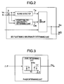
- Fig. 2 shows the details of the self commutating/abnormality determining unit 42.
- the system voltage Vs and the tie-point current Ic are respectively inputted to a self commutated-operation detector and a power failure/overvoltage detector.
- the island detector detects the state of island operation from the tie-point current Ic and the system voltage Vs, and upon detecting the state of self commutated operation the island detector sets the value of a signal Ta to a "1," and outputs it to an OR circuit.
- the power failure/overvoltage detector detects the degree of a drop or rise in voltage, and when an abnormality is detected, the power failure/overvoltage detector sets the value of a signal Oa to a "1,” and outputs it to the OR circuit.
- the interconnection allowance signal Ra ("0" when interconnection is allowed, and "1" when it is not allowed), which is the output of the phase determining unit, is also inputted to the OR circuit.
- the OR circuit outputs the opening signal So to the circuit breaker 3a to open the circuit breaker 3a or continue the open state of the circuit breaker 3a.
- the OR circuit outputs the self commutating allowance signal MD to the phase detector 41 and the converter controller 40.
- Fig. 3 shows the details of the phase determining unit.
- the phase difference signal ⁇ ⁇ outputted from the phase detector is inputted to a level determining unit, and when ⁇ ⁇ is a value in the neighborhood of zero which does not affect the converter and the load at the time of closing the circuit breaker, the system interconnection allowance signal Ra is set to a "0," and is outputted to the self commutating/abnormality determining unit.
- the level for determining the phase difference if, for example, the phase difference between the system voltage Vs and the converter voltage Vc is A, and the reactance from the power system to the converter is X, power P which is determined from the following formula (1) is absorbed or released between the converter and the system when the circuit breaker is closed.
- a phase difference A that this power Po becomes sufficiently small with respect to the converter capacity is selected to minimize the effect on the converter.
- Po Vs•Vc•sinA/X[W]
- the aforementioned determining level may be provided with hysteresis to prevent the interconnection allowance signal Ra of the output from repeating the values of "1" and "0" step by step in a case where the value of ⁇ ⁇ is close to the value of a phase difference A in the aforementioned determining level.
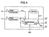
- Fig. 4 shows the details of the phase detector.
- the phase signal ⁇ c detected from the output voltage Vc of the converter by a phase calculator the difference between the same and the phase signal ⁇ s detected from the system voltage Vs by a phase calculator is calculated by a subtractor 7a, and the calculated phase difference ⁇ ⁇ is outputted to the phase determining unit. Further, the phase signal ⁇ c is outputted to the converter controller, and is inputted to a phase holding unit as well.
- the self commutating allowance signal MD is inputted to the phase holding unit, and when the self commutating allowance signal MD indicates the self commutated operation, the mode shifts to a self-oscillation mode at a system frequency at the phase persisting at that point of time, and the phase holding unit outputs a phase signal ⁇ ch to an adder 8a.
- the phase difference ⁇ ⁇ is inputted to the limiter, which in turn limits a correction amount ⁇ ⁇ with a phase difference corresponding to a frequency variation allowed for the system, and outputs a limited value ⁇ ⁇ ' to the adder 8a.
- the adder 8a adds the phase signals ⁇ ch and ⁇ ⁇ ', and outputs the added result ⁇ c' to the converter controller.
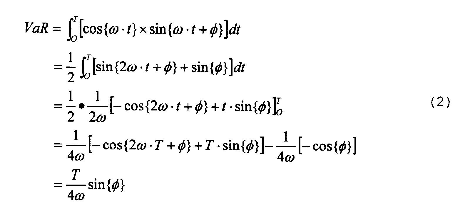
- phase calculator A description will be given of the phase calculator.
- cos( ⁇ t + ⁇ ) is calculated in accordance with expressions of Fourier transformation shown in formulae (4) and (5) so as to obtain VbR and VbI.
- cos ( ⁇ t) and sin ( ⁇ t) are internal oscillation signals
- t is the time
- ⁇ is the phase difference with an internal oscillator.
- the calculated results VR and VI are transformed into ac signals Vcos and Vsin by using the phases cos( ⁇ t) and sin( ⁇ t) of the internal oscillators through coordinate transformation using formula (8).
- phase angle ⁇ c is calculated in accordance with an arithmetic expression shown in formula (9).
- ⁇ c Atan(Vsin/Vcos)
- phase signal ⁇ s of the system voltage Vs is also determined in the same way as described above.
- Fig. 5 shows the configuration of the converter controller in accordance with this embodiment.
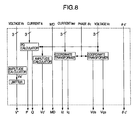
- Fig. 6 shows the details of the detector of the converter controller
- Fig. 7 shows the details of the controller of the converter controller.
- the converter controller calculates active power P and reactive power Q being outputted to the system by a PQ calculator on the basis of the current detection value Ic and the voltage detection value Vc.
- the active power P and the reactive power Q thus obtained are respectively inputted to an active power regulator APR and a reactive power regulator AQR shown in Fig. 7, and the active power regulator APR and the reactive power regulator AQR calculate current command values Idl* and Iql* to allow the active power P and the reactive power Q to agree with command values P* and Q*, outputs them to switchers 10a and 10b, respectively.
- a voltage amplitude detection value Vs' at the tie point of the converter is calculated by being inputted to an amplitude calculator shown in Fig.
- An amplitude value Vc' of the output voltage Vc of the converter is also calculated by another amplitude calculator shown in Fig. 6, and is inputted to a subtractor 7f as a feedback signal for an automatic voltage regulator AVR shown in Fig. 7.
- the voltage amplitude detection value Vs' is inputted to the limiter shown in Fig. 6, and the limiter limits the voltage amplitude detection value Vs' within a rated range of the system voltage and outputs it to a filter (not shown).
- a voltage amplitude V* without a highfrequency component removed by the filter is outputted to the subtractor 7f so as to be used as a command value for the voltage regulator AVR.
- the subtractor 7f outputs the result of calculation to the voltage regulator AVR, and an output Id2* of the voltage regulator AVR is inputted to a switcher 10a.
- a q-axis component Iq of the current feedback is inputted to a switcher 10b, and the switcher 10b outputs either Iq or Iql*.
- an integral value which is held in the active power regulator APR and an integral value which is held in the voltage regulator AVR use a common memory Za, and a setting is provided such that the integral value not being used for control agrees with the integral value being used for control.
- the phase signal ⁇ c is inputted to a coordinate transformer at the current Iacr and a coordinate transformer at the voltage Vc shown in Fig. 6.
- Each coordinate transformer transforms the three-phase ac signal into two-axis dc quantities from the phase signal ⁇ c, and transforms the current Iacr into Id and Iq and the voltage Vc into Vds and Vqs.
- the d-axis component Vds and the q-axis component Vqs of the voltage are respectively inputted to switchers 10c and 10d.
- Inputted to the switchers 10c and 10d are fixed values of the magnitude (1.0 pu) of the d-axis component and the magnitude (0.0 pu) of the q-axis component of the voltage detection value to be normally detected in the grid connected operation. If it is assumed that output signals of the respective switchers 10c and 10d are Vds' and Vqs', either Vds and Vqs or 1.0 pu and 0.0 pu are outputted as outputs.
- Outputs Id* and Iq* of the switcher 10a and the switcher 10b shown in Fig. 7 are respectively inputted to subtractors 7b and 7c, differences between the same and the feedback values Id and Iq of the current Iacr are calculated by the subtractors 7b and 7c, and the results are respectively outputted to a d-axis current regulator ACRd and a q-axis current regulator ACRq.
- the outputs Id* and Iq* of the switchers 10a and 10b are respectively outputted to noninterfering-component calculators wL.
- the outputs from the current regulator ACRd and the current regulator ACRq are respectively inputted to an adder-subtractor 9a and an adder-subtractor 9b.
- the noninterfering-component calculator wL calculates a noninterfering component from the q-axis current command value Iq*, and outputs it to the adder-subtractor 9a.
- the noninterfering-component calculator wL calculates a noninterfering component from the d-axis current command value Id*, and outputs it to the adder-subtractor 9b.
- the adder-subtractors 9a and 9b respectively add the d-axis component Vds' and the q-axis component Vqs' of the voltage detection value, and output the results of the arithmetic operation, Vd* and Vq*, to a two-phase/three-phase coordinate transformer.
- the two-phase/three-phase coordinate transformer transforms the signals Vd* and Vq* inputted by using the phase signal ⁇ c' into a three-phase alternating current, and outputs it to a PWM computing unit.
- the PWM computing unit subjects the output from the two-phase/three-phase coordinate transformer to a PWM operation, and outputs a gate pulse Gp.
- the two-phase/three-phase coordinate transformer effects transformation into a three-phase alternating current by using ⁇ c' which is the sum of ⁇ ch and ⁇ ⁇ c', i.e., ⁇ ⁇ whose value has been limited by the limiter, it is possible to adjust the output phase of the converter so as to eliminate ⁇ ⁇ .
- the self commutating allowance signal MD is inputted to the switchers 10a and 10b shown in Fig. 7 and the switchers 10c and 10d shown in Fig. 6.
- the switcher 10a selects Id2* as Id*
- the switcher 10b selects Iq as Iq*
- the switcher 10c uses the fixed value of 1.0 pu for Vds' to fix a feedforward component of the voltage
- the switcher 10d uses the fixed value of 0.0 pu for Vqs'.
- the output phase of the converter system can be adjusted in such a manner as to coincide with the phase of the system when the system voltage has returned during self commutated operation. Accordingly, in this embodiment, an overcurrent of the converter and an effect on the load are small when the system voltage has returned during self commutated operation.
- the circuit breaker 3a can be closed by directly operating the converter system when the phases have coincided with each other, equipment such as an interconnection protector is not required.
- the phase detection signal since part of the output of the phase detector is merely held during transfer to self commutated operation, and the coordinate transformation in current detection uses the signal from the phase detector as it is, the phase detection signal does not change abruptly during a shift to self commutated operation or a return to system interconnection, so that the converter can be controlled stably.
- the current control system is used in common for the grid connected operation and the self commutated operation, so that it is possible to suppress sudden fluctuations in the controlled variables.
- current control is used at the time of self commutated operation, in a case such as where the load has fluctuates and exceeds the capacity of the converter, it is possible to prevent an overcurrent by the operation of the limiter in current control.
- the amount of correction of the phase difference ⁇ ⁇ is provided with a limit, and the phase is adjusted with an amount of phase correction falling within an amount corresponding to the portion of frequency variation allowed for the system, a return is possible from self commutated operation to grid connected operation while suppressing the frequency variation of the load to a minimum.
- the system-side voltage Vs of the circuit breaker is used as the voltage command value V* of the voltage regulator AVR, and a limiter within the allowable range of the voltage which is determined by the system is provided to use its output as a command value, when the system voltage has dropped during self commutated operation, a lower limit of the limit serves as a voltage command value, while when the system voltage has returned, the voltage of the self commutated system can be made to agree with the voltage of the system.
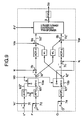
- Figs. 8 and 9 respectively illustrate a detector and a controller of the converter controller 40 in accordance with a second embodiment of the invention.
- feedforward detection values Vds and Vqs of the voltage of the converter controller are also used during self commutated operation as during grid connected operation.
- feedforward detection values of the voltage are constantly used, it is possible to follow at high speed a voltage fluctuation when an accident or the like has occurred in a transmission line during self commutated operation, and it is possible to prevent an overcurrent in the converter.
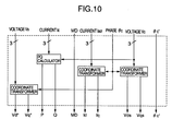
- Figs. 10 and 11 respectively illustrate a detector and a controller of the converter controller 40 in accordance with a third embodiment of the invention.
- the configuration of the converter controller of the first embodiment during self commutated operation is different.
- a d-axis voltage regulator AVRd is used instead of the active power regulator APR, and a q-axis voltage regulator AVRq is used instead of the reactive power regulator AQR.
- Figs. 12 and 13 respectively illustrate a detector and a fourth of the converter controller 40 in accordance with a third embodiment of the invention.
- the configuration of the converter controller of the third embodiment during self commutated operation is different, and the fixed phase ⁇ c' is used in the coordinate transformation of the current as well.
- the d-axis component and the q-axis component can be controlled by the current regulator, there is an advantage in suppressing an overcurrent.
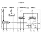
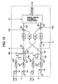
- Figs. 14 and 15 respectively illustrate a detector and a controller of the converter controller 40 in accordance with a fifth embodiment of the invention.
- the configuration of the converter controller of the third embodiment during self commutated operation is different, and the phase detection signal ⁇ c is used as the reference phase for two-phase/three-phase transformation.
- the phase detection signal ⁇ c is used as the reference phase for two-phase/three-phase transformation.
- Figs. 16 and 17 respectively illustrate a detector and a controller of the converter controller 40 in accordance with a sixth embodiment of the invention.
- the configuration of the converter controller of the third embodiment during self commutated operation is changed, and the fixed signal ⁇ c' is used as the reference phase signal for coordinate conversion for calculating a feedforward component of the voltage.
- the fixed signal ⁇ c' is used as the reference phase signal for coordinate conversion for calculating a feedforward component of the voltage.
- both the d-axis component and the q-axis component can be controlled by the current regulator, there is an advantage in suppressing an overcurrent.
- a superconductive energy storage system is provided instead of the secondary battery 5a of the first embodiment, as shown in Fig. 18.
- a superconductive coil 100 is installed in a dc portion of the power converter 30, and the superconductive energy storage system transmits and receives electric power to and from the system in response to commands from the system controller 50.
- self commutated operation of the superconductive energy storage system is made possible.
- a photovoltaic power generator is provided instead of the secondary battery 5a of the first embodiment, as shown in Fig. 19.
- a solar cell panel 101 is installed in a dc portion of the converter 30 of the photovoltaic power generator, and releases electric power to the system in response to a command from the system controller 50.
- a wind power generation system 4b having an inverter and a converter is provided, as shown in Fig. 20. Dc portion of the inverter and the converter are used in common, and the secondary battery 5a for storing electric energy is installed. Electric power is absorbed from or released to the system in response to a command from the system controller 50.
- a plurality of wind power generation systems 4b may be provided.
- a dc power transmission system 102 is provided, as shown in Fig. 21.
- the output of the dc power transmission system supplies electric power to the system from the converter.
Landscapes
- Engineering & Computer Science (AREA)
- Power Engineering (AREA)
- Electromagnetism (AREA)
- Sustainable Development (AREA)
- Sustainable Energy (AREA)
- Physics & Mathematics (AREA)
- Life Sciences & Earth Sciences (AREA)
- General Physics & Mathematics (AREA)
- Radar, Positioning & Navigation (AREA)
- Automation & Control Theory (AREA)
- Inverter Devices (AREA)
- Supply And Distribution Of Alternating Current (AREA)
- Control Of Electrical Variables (AREA)
- Ac-Ac Conversion (AREA)
Abstract
Description



Claims (8)
- A power converter system comprising:switching on/off means (3a) having one terminal connected to a power system and another terminal connected to a load (20);a transformer (6a) for interconnection;a power converter; anda controller (50) for controlling said power converter,wherein said power converter supplies electric power to a load (20) and is connected to said load and to a power system through said switching on/off means, and said controller outputs a control signal for adjusting an output phase of said power converter on the basis of an ac voltage on a power system side of said switching on/off means and an ac voltage on a load side thereof so as to eliminate a phase difference between the power system-side ac voltage and the load-side ac voltage.
- The power converter system according to claim 1, wherein said controller (50) outputs a signal for opening or closing said switching on/off means in accordance with the phase difference.
- The power converter system according to claim 2, wherein said controller has a current controlling system for switching over a current command between system interconnection operation and self commutated operation.
- A power converter system comprising:switching on/off means (3a) having one terminal connected to a power system and another terminal connected to a load (20);a transformer (6a) for interconnection;a power converter (30); anda controller (50) for controlling said power converter,wherein said power converter supplies electric power to a load and is connected to said load and to a power system through said switching on/off means, and said controller outputs a signal for opening or closing said switching on/off means on the basis of an ac voltage on a power system side of said switching on/off means and an ac voltage on a load side thereof in response to a phase difference between the power system-side ac voltage and the load-side ac voltage.
- The power converter system according to claim 4, wherein said controller (50) outputs the signal for closing said switching on/off means when the phase difference is close to zero.
- The power converter system according to claim 1, wherein said power converter is further connected to a wind power generator system, and said power converter has energy storage means.
- The power converter system according to claim 4, wherein said power converter is further connected to a wind power generator system, and said power converter has energy storage means.
- A method of controlling a power converter (30) which supplies electric power to a load (20) and is connected to the load and to a power system through switching on/off means (3a), comprising the steps of:adjusting an output phase of said power converter on the basis of an ac voltage on a power system side of said switching on/off means and an ac voltage on a load side thereof so as to eliminate a phase difference between the power system-side ac voltage and the load-side ac voltage during self commutated operation of said converter; andclosing and switching on/off means when said phase difference is close to zero.
Applications Claiming Priority (2)
| Application Number | Priority Date | Filing Date | Title |
|---|---|---|---|
| JP37267899 | 1999-12-28 | ||
| JP37267899A JP3547355B2 (en) | 1999-12-28 | 1999-12-28 | Power conversion system |
Publications (2)
| Publication Number | Publication Date |
|---|---|
| EP1113560A2 true EP1113560A2 (en) | 2001-07-04 |
| EP1113560A3 EP1113560A3 (en) | 2003-05-14 |
Family
ID=18500869
Family Applications (1)
| Application Number | Title | Priority Date | Filing Date |
|---|---|---|---|
| EP20000128616 Withdrawn EP1113560A3 (en) | 1999-12-28 | 2000-12-28 | Power converter system and method of controlling power converter |
Country Status (6)
| Country | Link |
|---|---|
| US (1) | US6304468B2 (en) |
| EP (1) | EP1113560A3 (en) |
| JP (1) | JP3547355B2 (en) |
| KR (1) | KR20010062746A (en) |
| CN (1) | CN1309451A (en) |
| TW (1) | TW493311B (en) |
Cited By (4)
| Publication number | Priority date | Publication date | Assignee | Title |
|---|---|---|---|---|
| DE202011005048U1 (en) * | 2011-04-08 | 2011-10-11 | Rudolf Baier | Electrical power distribution device for a building |
| US8041466B2 (en) | 2006-10-02 | 2011-10-18 | Vestas Wind Systems A/S | Method for operating a wind turbine connected to a utility grid during a utility disturbance, wind turbine and wind park |
| EP2409374A4 (en) * | 2009-04-30 | 2013-05-01 | Byd Co Ltd | ELECTRICAL POWER PLANT ON BATTERY |
| EP4184779A1 (en) * | 2019-04-25 | 2023-05-24 | Mitsubishi Electric Corporation | Control device and power conversion device |
Families Citing this family (90)
| Publication number | Priority date | Publication date | Assignee | Title |
|---|---|---|---|---|
| JP2002112553A (en) * | 2000-09-29 | 2002-04-12 | Canon Inc | Power conversion device, control method therefor, and power generation device |
| DE10136974A1 (en) * | 2001-04-24 | 2002-11-21 | Aloys Wobben | Method for operating a wind turbine |
| JP4497758B2 (en) * | 2001-06-19 | 2010-07-07 | 株式会社キューヘン | Grid interconnection converter |
| JP3982232B2 (en) * | 2001-10-25 | 2007-09-26 | 株式会社日立製作所 | Sensorless control device and control method for synchronous generator |
| JP3724793B2 (en) * | 2002-01-15 | 2005-12-07 | 東洋電機製造株式会社 | Single operation detection device for grid interconnection inverter and control method thereof |
| US6980911B2 (en) * | 2003-02-28 | 2005-12-27 | Kohler Co. | Automatic transfer switch system with synchronization control |
| US7042110B2 (en) * | 2003-05-07 | 2006-05-09 | Clipper Windpower Technology, Inc. | Variable speed distributed drive train wind turbine system |
| US7225087B1 (en) | 2003-07-09 | 2007-05-29 | Asco Power Technologies, L.P. | Method and apparatus for detecting unintentional islanding of utility grid |
| JP4459602B2 (en) * | 2003-12-05 | 2010-04-28 | 財団法人鉄道総合技術研究所 | Converter output / phase control method |
| US7183667B2 (en) * | 2003-12-19 | 2007-02-27 | Square D Company | Method and apparatus for power inverter synchronization |
| US7203078B2 (en) | 2004-06-23 | 2007-04-10 | General Electric Company | Dual mode rectifier, system and method |
| US7362600B2 (en) * | 2004-10-01 | 2008-04-22 | Continental Automotive Systems Us, Inc. | Method and apparatus for cycle error correction for a power converter device, such as an electronic power inverter |
| US11881814B2 (en) | 2005-12-05 | 2024-01-23 | Solaredge Technologies Ltd. | Testing of a photovoltaic panel |
| US10693415B2 (en) | 2007-12-05 | 2020-06-23 | Solaredge Technologies Ltd. | Testing of a photovoltaic panel |
| US8816535B2 (en) | 2007-10-10 | 2014-08-26 | Solaredge Technologies, Ltd. | System and method for protection during inverter shutdown in distributed power installations |
| US11296650B2 (en) | 2006-12-06 | 2022-04-05 | Solaredge Technologies Ltd. | System and method for protection during inverter shutdown in distributed power installations |
| US8947194B2 (en) | 2009-05-26 | 2015-02-03 | Solaredge Technologies Ltd. | Theft detection and prevention in a power generation system |
| US11569659B2 (en) | 2006-12-06 | 2023-01-31 | Solaredge Technologies Ltd. | Distributed power harvesting systems using DC power sources |
| US9112379B2 (en) | 2006-12-06 | 2015-08-18 | Solaredge Technologies Ltd. | Pairing of components in a direct current distributed power generation system |
| US11855231B2 (en) | 2006-12-06 | 2023-12-26 | Solaredge Technologies Ltd. | Distributed power harvesting systems using DC power sources |
| US11888387B2 (en) | 2006-12-06 | 2024-01-30 | Solaredge Technologies Ltd. | Safety mechanisms, wake up and shutdown methods in distributed power installations |
| US8473250B2 (en) | 2006-12-06 | 2013-06-25 | Solaredge, Ltd. | Monitoring of distributed power harvesting systems using DC power sources |
| US8618692B2 (en) | 2007-12-04 | 2013-12-31 | Solaredge Technologies Ltd. | Distributed power system using direct current power sources |
| US9130401B2 (en) | 2006-12-06 | 2015-09-08 | Solaredge Technologies Ltd. | Distributed power harvesting systems using DC power sources |
| US8013472B2 (en) | 2006-12-06 | 2011-09-06 | Solaredge, Ltd. | Method for distributed power harvesting using DC power sources |
| US8319471B2 (en) | 2006-12-06 | 2012-11-27 | Solaredge, Ltd. | Battery power delivery module |
| US8963369B2 (en) | 2007-12-04 | 2015-02-24 | Solaredge Technologies Ltd. | Distributed power harvesting systems using DC power sources |
| US11309832B2 (en) | 2006-12-06 | 2022-04-19 | Solaredge Technologies Ltd. | Distributed power harvesting systems using DC power sources |
| US12316274B2 (en) | 2006-12-06 | 2025-05-27 | Solaredge Technologies Ltd. | Pairing of components in a direct current distributed power generation system |
| US11687112B2 (en) | 2006-12-06 | 2023-06-27 | Solaredge Technologies Ltd. | Distributed power harvesting systems using DC power sources |
| US11735910B2 (en) | 2006-12-06 | 2023-08-22 | Solaredge Technologies Ltd. | Distributed power system using direct current power sources |
| US9088178B2 (en) | 2006-12-06 | 2015-07-21 | Solaredge Technologies Ltd | Distributed power harvesting systems using DC power sources |
| US8384243B2 (en) | 2007-12-04 | 2013-02-26 | Solaredge Technologies Ltd. | Distributed power harvesting systems using DC power sources |
| US8319483B2 (en) | 2007-08-06 | 2012-11-27 | Solaredge Technologies Ltd. | Digital average input current control in power converter |
| JP2008278700A (en) * | 2007-05-02 | 2008-11-13 | Ntt Facilities Inc | Distributed power generator and power quality maintenance control method |
| EP3561881A1 (en) | 2007-12-05 | 2019-10-30 | Solaredge Technologies Ltd. | Testing of a photovoltaic panel |
| US8049523B2 (en) | 2007-12-05 | 2011-11-01 | Solaredge Technologies Ltd. | Current sensing on a MOSFET |
| WO2009072075A2 (en) | 2007-12-05 | 2009-06-11 | Solaredge Technologies Ltd. | Photovoltaic system power tracking method |
| EP2232690B1 (en) | 2007-12-05 | 2016-08-31 | Solaredge Technologies Ltd. | Parallel connected inverters |
| EP3496258B1 (en) | 2007-12-05 | 2025-02-05 | Solaredge Technologies Ltd. | Safety mechanisms in distributed power installations |
| US11264947B2 (en) | 2007-12-05 | 2022-03-01 | Solaredge Technologies Ltd. | Testing of a photovoltaic panel |
| EP4145691A1 (en) | 2008-03-24 | 2023-03-08 | Solaredge Technologies Ltd. | Switch mode converter including auxiliary commutation circuit for achieving zero current switching |
| EP3121922B1 (en) | 2008-05-05 | 2020-03-04 | Solaredge Technologies Ltd. | Direct current power combiner |
| US8068352B2 (en) * | 2008-12-19 | 2011-11-29 | Caterpillar Inc. | Power inverter control for grid-tie transition |
| KR101061589B1 (en) * | 2008-12-29 | 2011-09-02 | 포스코파워 주식회사 | Output phase angle determination device of power converter for fuel cell power generation system |
| TWI393320B (en) * | 2009-06-16 | 2013-04-11 | Mitsubishi Heavy Ind Ltd | System stabilization devices, methods, and wind power generation systems |
| JP5358356B2 (en) * | 2009-08-31 | 2013-12-04 | 株式会社日立製作所 | Semiconductor power converter |
| US12418177B2 (en) | 2009-10-24 | 2025-09-16 | Solaredge Technologies Ltd. | Distributed power system using direct current power sources |
| US8710699B2 (en) | 2009-12-01 | 2014-04-29 | Solaredge Technologies Ltd. | Dual use photovoltaic system |
| US7915868B1 (en) * | 2009-12-23 | 2011-03-29 | General Electric Company | Method of synchronizing a turbomachine generator to an electric grid |
| US8766696B2 (en) | 2010-01-27 | 2014-07-01 | Solaredge Technologies Ltd. | Fast voltage level shifter circuit |
| GB2485527B (en) | 2010-11-09 | 2012-12-19 | Solaredge Technologies Ltd | Arc detection and prevention in a power generation system |
| US10673229B2 (en) | 2010-11-09 | 2020-06-02 | Solaredge Technologies Ltd. | Arc detection and prevention in a power generation system |
| US10230310B2 (en) | 2016-04-05 | 2019-03-12 | Solaredge Technologies Ltd | Safety switch for photovoltaic systems |
| US10673222B2 (en) | 2010-11-09 | 2020-06-02 | Solaredge Technologies Ltd. | Arc detection and prevention in a power generation system |
| GB2486408A (en) | 2010-12-09 | 2012-06-20 | Solaredge Technologies Ltd | Disconnection of a string carrying direct current |
| GB2483317B (en) | 2011-01-12 | 2012-08-22 | Solaredge Technologies Ltd | Serially connected inverters |
| TWI497858B (en) * | 2011-01-21 | 2015-08-21 | Ibm | Method and system for detecting conflicts between outage requests and power supply guarantee requests in power grid |
| JP5877648B2 (en) * | 2011-03-23 | 2016-03-08 | 北陸電力株式会社 | Distributed power system |
| US8570005B2 (en) | 2011-09-12 | 2013-10-29 | Solaredge Technologies Ltd. | Direct current link circuit |
| JP5760930B2 (en) * | 2011-10-07 | 2015-08-12 | 日新電機株式会社 | Control device for power conversion device for grid connection, and power conversion device for grid connection |
| GB2498365A (en) | 2012-01-11 | 2013-07-17 | Solaredge Technologies Ltd | Photovoltaic module |
| GB2498790A (en) | 2012-01-30 | 2013-07-31 | Solaredge Technologies Ltd | Maximising power in a photovoltaic distributed power system |
| US9853565B2 (en) | 2012-01-30 | 2017-12-26 | Solaredge Technologies Ltd. | Maximized power in a photovoltaic distributed power system |
| GB2498791A (en) | 2012-01-30 | 2013-07-31 | Solaredge Technologies Ltd | Photovoltaic panel circuitry |
| GB2499991A (en) | 2012-03-05 | 2013-09-11 | Solaredge Technologies Ltd | DC link circuit for photovoltaic array |
| EP3499695B1 (en) | 2012-05-25 | 2024-09-18 | Solaredge Technologies Ltd. | Circuit for interconnected direct current power sources |
| US10115841B2 (en) | 2012-06-04 | 2018-10-30 | Solaredge Technologies Ltd. | Integrated photovoltaic panel circuitry |
| US9941813B2 (en) | 2013-03-14 | 2018-04-10 | Solaredge Technologies Ltd. | High frequency multi-level inverter |
| US9548619B2 (en) | 2013-03-14 | 2017-01-17 | Solaredge Technologies Ltd. | Method and apparatus for storing and depleting energy |
| EP2779251B1 (en) | 2013-03-15 | 2019-02-27 | Solaredge Technologies Ltd. | Bypass mechanism |
| JP6043223B2 (en) * | 2013-03-21 | 2016-12-14 | 株式会社デンソー | Cooperation system of photovoltaic power generation and storage battery |
| CN103311907A (en) * | 2013-03-23 | 2013-09-18 | 南京科明自动化设备有限公司 | Synchronizing checking relay and angle locking method of synchronizing checking relay |
| JP6273874B2 (en) * | 2014-02-04 | 2018-02-07 | 日新電機株式会社 | Control device for power conversion device for grid connection, and power conversion device for grid connection |
| US9318974B2 (en) | 2014-03-26 | 2016-04-19 | Solaredge Technologies Ltd. | Multi-level inverter with flying capacitor topology |
| JP6351331B2 (en) * | 2014-03-28 | 2018-07-04 | 株式会社東芝 | Power converter |
| US9350281B2 (en) | 2014-05-09 | 2016-05-24 | Alonso Rodiguez | Circuit and method for frequency synthesis for signal detection in automatic voltage regulation for synchronous generators |
| JP6631311B2 (en) * | 2016-02-25 | 2020-01-15 | 株式会社明電舎 | Power generation system |
| CN107153212B (en) | 2016-03-03 | 2023-07-28 | 太阳能安吉科技有限公司 | Method for mapping power generation facilities |
| US11081608B2 (en) | 2016-03-03 | 2021-08-03 | Solaredge Technologies Ltd. | Apparatus and method for determining an order of power devices in power generation systems |
| US10599113B2 (en) | 2016-03-03 | 2020-03-24 | Solaredge Technologies Ltd. | Apparatus and method for determining an order of power devices in power generation systems |
| US10181728B2 (en) * | 2016-03-22 | 2019-01-15 | General Electric Company | Smart grid synchronization scheme |
| US11018623B2 (en) | 2016-04-05 | 2021-05-25 | Solaredge Technologies Ltd. | Safety switch for photovoltaic systems |
| US11177663B2 (en) | 2016-04-05 | 2021-11-16 | Solaredge Technologies Ltd. | Chain of power devices |
| US12057807B2 (en) | 2016-04-05 | 2024-08-06 | Solaredge Technologies Ltd. | Chain of power devices |
| EP3316438A1 (en) * | 2016-10-26 | 2018-05-02 | MHI Vestas Offshore Wind A/S | Controlling power exchange from self-commutated converters |
| JP7000689B2 (en) * | 2017-03-10 | 2022-01-19 | 株式会社明電舎 | Independent / interconnected operation automatic switching device in hydroelectric power generation system |
| CN108347063B (en) * | 2018-01-17 | 2021-08-24 | 武汉理工大学 | A ship photovoltaic grid-connected power generation system based on supercapacitor energy storage |
| US12074535B2 (en) | 2019-04-25 | 2024-08-27 | Mitsubishi Electric Corporation | Control device and power conversion device |
| CN115102149B (en) * | 2022-08-10 | 2025-10-28 | 华北电力大学 | A grid-type converter overcurrent suppression system and method |
Family Cites Families (16)
| Publication number | Priority date | Publication date | Assignee | Title |
|---|---|---|---|---|
| US4218625A (en) * | 1978-01-25 | 1980-08-19 | Beckwith Robert W | Synchronizing check relay |
| JPS5846957B2 (en) * | 1979-02-21 | 1983-10-19 | 株式会社東芝 | Commutation angle control device |
| DE3236071A1 (en) * | 1982-07-09 | 1984-01-12 | Siemens AG, 1000 Berlin und 8000 München | Device for parallel supply into an AC or three-phase network |
| JPH0773426B2 (en) * | 1984-11-09 | 1995-08-02 | 株式会社東芝 | Power converter control device |
| JP2507387B2 (en) * | 1987-02-13 | 1996-06-12 | 株式会社東芝 | Power converter |
| US4797570A (en) * | 1987-07-31 | 1989-01-10 | Westinghouse Electric Corp. | Automatic paralleling of AC power sources |
| JPH03256533A (en) * | 1990-03-02 | 1991-11-15 | Shikoku Sogo Kenkyusho:Kk | System linkage system |
| JP2861313B2 (en) * | 1990-07-20 | 1999-02-24 | 富士電機株式会社 | Inverter control circuit for independent and interconnected operation |
| GB2264403B (en) * | 1992-02-18 | 1996-09-04 | Hitachi Ltd | An apparatus for controlling parallel running of inverters |
| DK171689B1 (en) * | 1993-09-01 | 1997-03-10 | Dancontrol Eng As | Method of regulating an electrical coupling for interconnecting an AC network with an asynchronous generator and coupling |
| US5625539A (en) * | 1994-05-30 | 1997-04-29 | Sharp Kabushiki Kaisha | Method and apparatus for controlling a DC to AC inverter system by a plurality of pulse-width modulated pulse trains |
| JP3255797B2 (en) * | 1994-06-17 | 2002-02-12 | 関西電力株式会社 | Operation control method of distributed power supply |
| JP2904023B2 (en) * | 1994-08-24 | 1999-06-14 | 日新電機株式会社 | Inverter for distributed power supply |
| AT408590B (en) * | 1998-03-02 | 2002-01-25 | Va Tech Elin Gmbh | METHOD FOR PARALLEL SWITCHING SYNCHRONOUS GENERATORS AND DEVICE FOR IMPLEMENTING THE METHOD |
| US6128204A (en) * | 1998-08-26 | 2000-10-03 | Northrop Grumman Corporation | Line power unit for micropower generation |
| US6140803A (en) * | 1999-04-13 | 2000-10-31 | Siemens Westinghouse Power Corporation | Apparatus and method for synchronizing a synchronous condenser with a power generation system |
-
1999
- 1999-12-28 JP JP37267899A patent/JP3547355B2/en not_active Expired - Fee Related
-
2000
- 2000-12-27 US US09/748,268 patent/US6304468B2/en not_active Expired - Lifetime
- 2000-12-27 KR KR1020000082643A patent/KR20010062746A/en not_active Withdrawn
- 2000-12-27 TW TW89128047A patent/TW493311B/en not_active IP Right Cessation
- 2000-12-28 EP EP20000128616 patent/EP1113560A3/en not_active Withdrawn
- 2000-12-28 CN CN00137562A patent/CN1309451A/en active Pending
Cited By (5)
| Publication number | Priority date | Publication date | Assignee | Title |
|---|---|---|---|---|
| US8041466B2 (en) | 2006-10-02 | 2011-10-18 | Vestas Wind Systems A/S | Method for operating a wind turbine connected to a utility grid during a utility disturbance, wind turbine and wind park |
| EP2409374A4 (en) * | 2009-04-30 | 2013-05-01 | Byd Co Ltd | ELECTRICAL POWER PLANT ON BATTERY |
| DE202011005048U1 (en) * | 2011-04-08 | 2011-10-11 | Rudolf Baier | Electrical power distribution device for a building |
| EP4184779A1 (en) * | 2019-04-25 | 2023-05-24 | Mitsubishi Electric Corporation | Control device and power conversion device |
| US12068610B2 (en) | 2019-04-25 | 2024-08-20 | Mitsubishi Electric Corporation | Control device |
Also Published As
| Publication number | Publication date |
|---|---|
| CN1309451A (en) | 2001-08-22 |
| JP2001190077A (en) | 2001-07-10 |
| US6304468B2 (en) | 2001-10-16 |
| JP3547355B2 (en) | 2004-07-28 |
| TW493311B (en) | 2002-07-01 |
| KR20010062746A (en) | 2001-07-07 |
| EP1113560A3 (en) | 2003-05-14 |
| US20010005321A1 (en) | 2001-06-28 |
Similar Documents
| Publication | Publication Date | Title |
|---|---|---|
| US6304468B2 (en) | Phase synchronization system for connecting a power converter to a power distribution system | |
| US7495936B2 (en) | Three-phase voltage-fed AC/DC converter | |
| US20210249862A1 (en) | Double synchronous unified virtual oscillator control for grid-forming and grid-following power electronic converters | |
| Amenedo et al. | Grid-forming converters control based on the reactive power synchronization method for renewable power plants | |
| EP0793869B1 (en) | Series compensator inserting real and reactive impedance into electric power system for damping power oscillations | |
| US20150092462A1 (en) | Control circuit and control method for inverter circuit, and control circuit and control method for power conversion circuit | |
| Saeedian et al. | A control technique based on distributed virtual inertia for high penetration of renewable energies under weak grid conditions | |
| JP4056852B2 (en) | Power converter | |
| EP4362306B1 (en) | Control device and power conversion device | |
| US20110019443A1 (en) | Series voltage compensator and method for series voltage compensation in electrical generators | |
| Modi et al. | Improved cascaded SOGI control for islanding-synchronization in photovoltaic system | |
| Gao et al. | Seamless transitions between grid-following and grid-forming control: A novel switching method | |
| WO2023053173A1 (en) | Power conversion device and power conversion system | |
| US7345379B2 (en) | Power converter with voltage and current fault setting | |
| Gurugubelli et al. | A new hybrid islanding detection technique for microgrid using virtual synchronous machine | |
| Sadeque et al. | On control schemes for grid-forming inverters | |
| Narula et al. | Tuning and evaluation of grid-forming converters for grid-support | |
| EP0607011B1 (en) | Control device for system interconnection inverter | |
| EP3869682B1 (en) | A method and a control device for controlling a power converter | |
| Chakraborty et al. | A control for preventing false tripping of grid-tied renewable systems with increased solar penetration and fluctuating load demand | |
| JP3598871B2 (en) | Power conversion system for grid connection with islanding detection function | |
| JP2008172971A (en) | Three-phase voltage type AC / DC converter | |
| CN118117610A (en) | Control method of wind power generation system and wind power generation system | |
| Ali et al. | Mixed AC/DC system stability under uncertainty | |
| Park et al. | Nonlinear optimization-based power-voltage control of grid-connected converter in weak grid |
Legal Events
| Date | Code | Title | Description |
|---|---|---|---|
| PUAI | Public reference made under article 153(3) epc to a published international application that has entered the european phase |
Free format text: ORIGINAL CODE: 0009012 |
|
| AK | Designated contracting states |
Kind code of ref document: A2 Designated state(s): AT BE CH CY DE DK ES FI FR GB GR IE IT LI LU MC NL PT SE TR |
|
| AX | Request for extension of the european patent |
Free format text: AL;LT;LV;MK;RO;SI |
|
| PUAL | Search report despatched |
Free format text: ORIGINAL CODE: 0009013 |
|
| AK | Designated contracting states |
Designated state(s): AT BE CH CY DE DK ES FI FR GB GR IE IT LI LU MC NL PT SE TR |
|
| AX | Request for extension of the european patent |
Extension state: AL LT LV MK RO SI |
|
| RIC1 | Information provided on ipc code assigned before grant |
Ipc: 7H 02J 3/38 B Ipc: 7H 02M 7/48 A |
|
| 17P | Request for examination filed |
Effective date: 20030915 |
|
| 17Q | First examination report despatched |
Effective date: 20031028 |
|
| AKX | Designation fees paid |
Designated state(s): AT BE CH CY DE DK ES FI FR GB GR IE IT LI LU MC NL PT SE TR |
|
| STAA | Information on the status of an ep patent application or granted ep patent |
Free format text: STATUS: THE APPLICATION IS DEEMED TO BE WITHDRAWN |
|
| 18D | Application deemed to be withdrawn |
Effective date: 20040508 |