EP1113445A2 - Verfahren und Vorrichtung zum Einkoppeln von Signalen in ein Multimedia-System - Google Patents
Verfahren und Vorrichtung zum Einkoppeln von Signalen in ein Multimedia-System Download PDFInfo
- Publication number
- EP1113445A2 EP1113445A2 EP00127622A EP00127622A EP1113445A2 EP 1113445 A2 EP1113445 A2 EP 1113445A2 EP 00127622 A EP00127622 A EP 00127622A EP 00127622 A EP00127622 A EP 00127622A EP 1113445 A2 EP1113445 A2 EP 1113445A2
- Authority
- EP
- European Patent Office
- Prior art keywords
- radio
- audio
- line
- signals
- inputs
- Prior art date
- Legal status (The legal status is an assumption and is not a legal conclusion. Google has not performed a legal analysis and makes no representation as to the accuracy of the status listed.)
- Granted
Links
Images
Classifications
-
- G—PHYSICS
- G11—INFORMATION STORAGE
- G11B—INFORMATION STORAGE BASED ON RELATIVE MOVEMENT BETWEEN RECORD CARRIER AND TRANSDUCER
- G11B31/00—Arrangements for the associated working of recording or reproducing apparatus with related apparatus
Definitions
- the invention relates to a method and a device for coupling Signals in a multimedia system according to the preamble of claim 1 and the preamble of claim 5.
- a car radio is known from German utility model 900750101, which has a removable front. When removed the Front will be additional controls or the introduction for the Sound-image carrier of a media player, for example a cassette drive, a CD drive or a DVD drive can be released. This means that the additional controls can be folded down actuated or the image sound carrier can be inserted into the media player.
- a car radio is known from German utility model 880262001, in whose cassette slot opening a plastic part is inserted or this can be removed.
- the removable plastic part protrudes partially into the cassette slot, while another part from the Cassette slot protrudes.
- a car radio is included in German patent DE-C-19899154 foldable front with a media player whose sound image carrier through a Opening in the housing of the car radio is fully insertable, the Opening is arranged so that when the front is folded down to introduce the Sound-image carrier is accessible, known. If the front is not folded down, that is Access locked.
- a component that can be removed from the car radio Recording of device-specific data, such as warranty card, code name, Device number or similar is provided, the removable component having the shape of a sound-image carrier.
- adapter cassettes are e.g. of CD players, in particular of CD Walkman known to record sound signals in a cassette car radio.
- a car radio which is a rectangular Car radio housing, on the front of a removable Control panel is attached, which control panel with the car radio housing over at least one contact bar is connected, via which contact bar at attached control panel entered using the buttons on the control panel
- Operating commands on a microcomputer provided in the car radio housing become transferable.
- the control panel has an infrared transmitter and There is an infrared receiver on the front of the car radio housing provided so that the control panel in the removed state as Remote control.
- From DE-A-197 37 325 is a communication system for a motor vehicle with a plurality of components, which are located in different places of the Motor vehicle are known.
- the individual components of the Communication systems are connected to each other via an optical bus.
- a microcomputer is provided for bus management.
- Each of the components The communication system is equipped with a memory for one Communication system individually characterizing system code signal provided, and the microcomputer is programmed so that it before the Activation of one of the components checks whether this is in memory Component the system code signal is stored or not.
- the Microcomputer only enables the operation of the component if in the Component memory the system code signal is stored.
- the object of the invention is to couple in new media enable stored signals in existing multimedia systems, avoiding the above problems.
- a multimedia system consists of an audio unit, one Video unit and a playback unit.
- the audio unit mostly has Audio inputs in the form of line-in inputs for stereo signals.
- a radio module is connected to line-in inputs.
- a receiver module At this radio module is a receiver module.
- a external player for new media available This player shows Line out outputs on.
- These line-out outputs are also used Radio module connected.
- This radio module is a Transmitter module.
- the audio unit is switched to a special operating mode in which the signals applied via the line-in inputs into the Audio unit taken over, amplified and in the multimedia system to the corresponding playback units can be distributed.
- the external The playback device is put into operation.
- the Radio module transmits the signals to the second radio module, which is connected to the Audio unit and its line-in inputs connected.
- This radio module receives the signals transmitted via radio and couples them via the line-in inputs into the audio system.
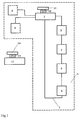
- Figure 1 shows the schematic structure of a multimedia system in one Motor vehicle and the structure of the playback device.
- the multimedia system 1 consists of an audio unit 2, one Microcomputer 3, a GPS unit 4, a GSM unit 5, and others connected units 6, and the audio playback units 8.9.
- the Units 2, 3, 4, 5, 6 are connected via a bus 7, in particular an optical bus, especially a bus built according to the MOST concept, connected. Such a bus is a ring structure.
- On the audio unit 2 are the audio playback units 8,9 which loudspeakers in particular are coupled.
- the audio unit 2 is for one a radio signal receiver and an amplifier unit for Audio signals arranged. These units are operated via the control units, which are assigned to the audio unit 2, controlled.
- the audio unit 2 has line-in inputs 10. These line-in inputs 10 are an input for stereo signals that come from an external device provided, i.e. Stereo signals sorted by left and right channels can be coupled. On these line-in inputs 10 is a Radio receiver module 11 placed and contacted them. In this Radio receiving module 11 are two radio receivers, each Receive signals for an audio channel.
- This Playback unit 12 has line-out outputs 13. Via these line-out outputs are stereo audio signals, ordered by left and right Audio channel provided.
- the playback unit 12 in which new media can be inserted and are playable, these media are played. Via the line-out outputs 13 these signals are sent to the radio transmitter module 14. in the Radio transmitter module 14 has one transmitter unit for each channel. The radio transmitter module 14 now transmits those via the line-out outputs 13 provided audio signals.
- the audio unit 2 is now switched to a special operating mode.
- This special operating mode are those via the line-in inputs 10 signals applied to the device and via the Playback units 8.9 played.
- the radio reception module 11 receives the signals sent by the radio transmitter module 14.
- the Radio reception module 11 receives these signals and couples them via the Line-in inputs 10 into the audio unit 2.
- this is Radio transmitter module as well as the radio receiver module with transmitters and Equipped with receivers that work according to the blue tooth concept.
- the radio receiver module with transmitters and Equipped with receivers that work according to the blue tooth concept.
- the Blue-Tooth concept is a radio interface, which for short Transmission paths is suitable and audio data is particularly suitable to transmit because the bandwidth of the transmitters is limited.
Landscapes
- Engineering & Computer Science (AREA)
- Multimedia (AREA)
- Fittings On The Vehicle Exterior For Carrying Loads, And Devices For Holding Or Mounting Articles (AREA)
- Input Circuits Of Receivers And Coupling Of Receivers And Audio Equipment (AREA)
- Details Of Television Systems (AREA)
- Communication Control (AREA)
Abstract
Description
- 1
- Multimedia-System
- 2
- Audio-Einheit
- 3
- Mikrocomputer
- 4
- GPS-Einheit
- 5
- GSM-Einheit
- 6
- weitere Einheiten
- 7
- Bus, insbesonderer MOST-Bus
- 8,9
- Audiowiedergabeeinheit
- 10
- Line-In-Eingänge
- 11
- Funkempfangsmodul
- 12
- Wiedergabegerät
- 13
- Line-Out-Ausgänge
- 14
- Funksendemodul
Claims (10)
- Verfahren zum Einkoppeln von Signalen in ein Multimedia-System (1) bestehend aus mindestens einer Audio-Einheit (2) mit angeschlossenen Audiowiedergabeeinheiten (8,9), wobei die Audio-Einheit (2) Line-In-Eingänge (10) für Audiosignale aufweist,
dadurch gekennzeichnet, dass
von einem Wiedergabegerät (12) mit Line-Out-Ausgänge (13) Audiosignale über eine Funkstrecke mittels einem Funksendemodul (14), welches die über die Line-Out-Ausgänge (13) bereitgestellten Audiosignale in Funksignale wandelt und einem Funkempfangsmodul (11), welches die empfangenen Funksignale in Audiosignale wandelt und über die Line-In-Eingänge (10) der Audio-Einheit (2) bereitstellt, übertragen werden, wobei diese Audiosignale in die Audio-Einheit (2) über die Line-In-Eingänge (10) einkoppelt werden. - Verfahren nach Anspruch 1,
dadurch gekennzeichnet, dass
die Funkübertragung nach dem Blue-Tooth-Konzept erfolgt. - Verfahren nach Anspruch 1 oder 2,
dadurch gekennzeichnet, dass
die Audio-Einheit (2) vor der Einkopplung der Ausiosignale über die Line-In-Eingänge (10) in einen Sonderbetriebsmodus geschaltet wird. - Verfahren nach einem oder mehreren der vorangehenden Ansprüche,
dadurch gekennzeichnet, dass
die Audio-Einheit (2) nach Beendigung der Einkopplung der Audiosignale über die Line-In-Eingänge (10) aus dem Sonderbetriebsmodus wieder in den Normalbetriebsmodus geschaltet wird. - Vorrichtung zur Einkopplung von Audiosignalen in ein Multimedia-System (1) bestehend aus mindestens einer Audio-Einheit (2) welche Line-In-Eingänge (10) für Streotonsignale aufweist, wobei die Audio-Einheit (2) an Audiowiedergabeeinheiten (8, 9) angeschlossen ist, über welche die Audiosignale der Audio-Einheit (2) wiedergegeben werden,
dadurch gekennzeichnet, dasseine Wiedergabeeinheit (12) für Audiosignale mit Line-Out-Ausgängen (13) vorgesehen ist,an die Line-Out-Ausgänge (13) eine Funksendemodul (14) angeschlossen ist, welches die an diesen Ausgängen anliegenden Audiosignale in Funksignale wandelt und per Funk überträgt,an die Line-In-Eingänge (10) ein Funkempfangsmodul (11) angeschlossen ist, welches die vom Funksendemodul (14) übertragenen Funksignale empfängt und in Audiosignale wandelt und über die Line-In-Eingänge (10) der Audio-Einheit(2), an welche das Funkempfangsmodul (14) angeschlossen ist, einkoppelt. - Vorrichtung nach Anspruch 5,
dadurch gekennzeichnet, dass
die Audio-Einheit (2) vor der Einkopplung der Audiosignale über die Line-In-Eingänge (10) in einen Sonderbetriebsmodus schaltet. - Vorrichtung nach Anspruch 5 oder 6,
dadurch gekennzeichnet, dass
die Wiedergabeeinheit (12) ein CD-Player, ein MP3-Player oder ein DVD-Player ist. - Vorrichtung nach einem oder mehreren der vorangehenden Ansprüche,
dadurch gekennzeichnet, dass
das Funksendemodul (14) zwei Funksender und das Funkempfangsmodul (11) zwei Funkempfänger aufweist, wobei jeweils ein Funksender des Funksendemoduls (14) mit einem Funkempfänger des Funkempfangsmoduls (11) in der Sendefrequenz übereinstimmt. - Vorrichtung nach einem oder mehreren der vorangehenden Ansprüche,
dadurch gekennzeichnet, dass
die Funktionseinheiten (2, 3, 4, 5, 6) des Multimedia-System (1) über einen Bus (7) miteinander kommunizieren, die Kommunikation über den Bus (7) von dem Mikrocomputer (3) gesteuert wird und der Bus (7) ein optischer Bus, insbesondere ein MOST-Bus, ist. - Vorrichtung nach einem oder mehreren der vorangehenden Ansprüche,
dadurch gekennzeichnet, daß
das die Funksender des Funksendemoduls (14) und die Funkempfänger des Funkempfangsmoduls (11) Blue-Tooth-Sender bzw. Blue-Tooth-Empfänger sind.
Applications Claiming Priority (2)
| Application Number | Priority Date | Filing Date | Title |
|---|---|---|---|
| DE19964063A DE19964063A1 (de) | 1999-12-30 | 1999-12-30 | Verfahren und Vorrichtung zum Einkoppeln von Signalen in ein Multimedia-System |
| DE19964063 | 1999-12-30 |
Publications (3)
| Publication Number | Publication Date |
|---|---|
| EP1113445A2 true EP1113445A2 (de) | 2001-07-04 |
| EP1113445A3 EP1113445A3 (de) | 2004-01-02 |
| EP1113445B1 EP1113445B1 (de) | 2007-09-12 |
Family
ID=7935187
Family Applications (1)
| Application Number | Title | Priority Date | Filing Date |
|---|---|---|---|
| EP00127622A Expired - Lifetime EP1113445B1 (de) | 1999-12-30 | 2000-12-16 | Verfahren und Vorrichtung zum Einkoppeln von Signalen in ein Multimedia-System |
Country Status (3)
| Country | Link |
|---|---|
| EP (1) | EP1113445B1 (de) |
| AT (1) | ATE373306T1 (de) |
| DE (2) | DE19964063A1 (de) |
Cited By (2)
| Publication number | Priority date | Publication date | Assignee | Title |
|---|---|---|---|---|
| DE102008037464A1 (de) | 2008-10-17 | 2010-04-22 | Lear Corporation Gmbh | Signalverarbeitungseinheit |
| WO2013081495A1 (en) * | 2011-12-01 | 2013-06-06 | Mikhail Leonidovich Lyubachev | Sound reproducing system |
Family Cites Families (4)
| Publication number | Priority date | Publication date | Assignee | Title |
|---|---|---|---|---|
| US4829570A (en) * | 1987-05-22 | 1989-05-09 | Recoton Corporation | Wireless remote speaker system |
| US4916532A (en) * | 1987-09-15 | 1990-04-10 | Jerry R. Iggulden | Television local wireless transmission and control |
| US5673323A (en) * | 1995-04-12 | 1997-09-30 | L. S. Research, Inc. | Analog spread spectrum wireless speaker system |
| DE19737325A1 (de) * | 1997-08-28 | 1999-03-11 | Grundig Ag | Kommunikationsanlage für ein Kraftfahrzeug |
-
1999
- 1999-12-30 DE DE19964063A patent/DE19964063A1/de not_active Ceased
-
2000
- 2000-12-16 AT AT00127622T patent/ATE373306T1/de not_active IP Right Cessation
- 2000-12-16 EP EP00127622A patent/EP1113445B1/de not_active Expired - Lifetime
- 2000-12-16 DE DE50014651T patent/DE50014651D1/de not_active Expired - Lifetime
Cited By (2)
| Publication number | Priority date | Publication date | Assignee | Title |
|---|---|---|---|---|
| DE102008037464A1 (de) | 2008-10-17 | 2010-04-22 | Lear Corporation Gmbh | Signalverarbeitungseinheit |
| WO2013081495A1 (en) * | 2011-12-01 | 2013-06-06 | Mikhail Leonidovich Lyubachev | Sound reproducing system |
Also Published As
| Publication number | Publication date |
|---|---|
| ATE373306T1 (de) | 2007-09-15 |
| EP1113445B1 (de) | 2007-09-12 |
| DE19964063A1 (de) | 2001-07-05 |
| EP1113445A3 (de) | 2004-01-02 |
| DE50014651D1 (de) | 2007-10-25 |
Similar Documents
| Publication | Publication Date | Title |
|---|---|---|
| DE69635921T2 (de) | Fernsteuergerät eines Audiosystems | |
| EP0676104B1 (de) | Musikabspielsystem mit dezentralen einheiten | |
| DE69837653T2 (de) | Automatische konfigurationseinrichtung für universale fernsteuerung | |
| DE10008440C2 (de) | Verfahren zum Betreiben eines Wiedergabegerätes zur Wiedergabe von auf einem Datenträger gespeicherten Daten in einem Fahrzeug und Verfahren zum Abrufen von Daten von einem Datenserver | |
| EP1025664A1 (de) | Rundfunkempfänger mit einem festplattenlaufwerk, einem schreib-/lesespeicher und einer anzeigevorrichtung | |
| DE4419189A1 (de) | Vorrichtung zur Diagnose von Kraftfahrzeugen | |
| EP0899161A1 (de) | Kommunikationsanlage für ein Kraftfahrzeug | |
| DE19939433A1 (de) | Autoradio mit abnehmbarer Bedieneinheit | |
| DE102020105624A1 (de) | Wiedergabevorrichtung, System und Datenserver | |
| DE102005008721A1 (de) | Diebstahlsicheres Auto-Audiosystem zum Anbringen und Abtrennen eines tragbaren MP3-Spielers und Kontrollverfahren dafür | |
| EP1113445B1 (de) | Verfahren und Vorrichtung zum Einkoppeln von Signalen in ein Multimedia-System | |
| DE4011597C2 (de) | ||
| DE3927384C2 (de) | ||
| DE10057261C2 (de) | Audiosystem für ein Kraftfahrzeug | |
| DE19646127C1 (de) | Gerät zur Archivierung von Speicherdaten | |
| DE3924896C1 (de) | ||
| EP1435096B1 (de) | Abspielgerät für speichermedien | |
| DE102004037735A1 (de) | Fahrerinformationssystem | |
| DE10101702A1 (de) | Kraftfahrzeug-Audiogerät | |
| DE19963083A1 (de) | Digitaler Rundfunkempfänger mit Aufzeichnungsmöglichkeit | |
| EP0881115A2 (de) | Sitzeinstellvorrichtung | |
| EP3772855A1 (de) | Wiedergabevorrichtung, system und datenserver | |
| DE19964062B4 (de) | Medium für einen Media-Player | |
| EP1430483A1 (de) | Vorrichtung zur wiedergabe von mp3-dateien | |
| DE3245073A1 (de) | Vorrichtung zur uebermittlung geschriebener informationen |
Legal Events
| Date | Code | Title | Description |
|---|---|---|---|
| PUAI | Public reference made under article 153(3) epc to a published international application that has entered the european phase |
Free format text: ORIGINAL CODE: 0009012 |
|
| AK | Designated contracting states |
Kind code of ref document: A2 Designated state(s): AT BE CH CY DE DK ES FI FR GB GR IE IT LI LU MC NL PT SE TR |
|
| AX | Request for extension of the european patent |
Free format text: AL;LT;LV;MK;RO;SI |
|
| PUAL | Search report despatched |
Free format text: ORIGINAL CODE: 0009013 |
|
| RIC1 | Information provided on ipc code assigned before grant |
Ipc: 7H 04H 5/00 B Ipc: 7G 11B 31/00 A Ipc: 7H 04B 1/20 B |
|
| AK | Designated contracting states |
Kind code of ref document: A3 Designated state(s): AT BE CH CY DE DK ES FI FR GB GR IE IT LI LU MC NL PT SE TR |
|
| AX | Request for extension of the european patent |
Extension state: AL LT LV MK RO SI |
|
| 17P | Request for examination filed |
Effective date: 20040702 |
|
| AKX | Designation fees paid |
Designated state(s): AT BE CH CY DE DK ES FI FR GB GR IE IT LI LU MC NL PT SE TR |
|
| 17Q | First examination report despatched |
Effective date: 20041004 |
|
| RAP1 | Party data changed (applicant data changed or rights of an application transferred) |
Owner name: VOLKSWAGEN AG |
|
| GRAP | Despatch of communication of intention to grant a patent |
Free format text: ORIGINAL CODE: EPIDOSNIGR1 |
|
| GRAS | Grant fee paid |
Free format text: ORIGINAL CODE: EPIDOSNIGR3 |
|
| GRAA | (expected) grant |
Free format text: ORIGINAL CODE: 0009210 |
|
| AK | Designated contracting states |
Kind code of ref document: B1 Designated state(s): AT BE CH CY DE DK ES FI FR GB GR IE IT LI LU MC NL PT SE TR |
|
| REG | Reference to a national code |
Ref country code: GB Ref legal event code: FG4D Free format text: NOT ENGLISH |
|
| REG | Reference to a national code |
Ref country code: CH Ref legal event code: EP |
|
| REF | Corresponds to: |
Ref document number: 50014651 Country of ref document: DE Date of ref document: 20071025 Kind code of ref document: P |
|
| REG | Reference to a national code |
Ref country code: IE Ref legal event code: FG4D Free format text: LANGUAGE OF EP DOCUMENT: GERMAN |
|
| GBT | Gb: translation of ep patent filed (gb section 77(6)(a)/1977) |
Effective date: 20071023 |
|
| PG25 | Lapsed in a contracting state [announced via postgrant information from national office to epo] |
Ref country code: FI Free format text: LAPSE BECAUSE OF FAILURE TO SUBMIT A TRANSLATION OF THE DESCRIPTION OR TO PAY THE FEE WITHIN THE PRESCRIBED TIME-LIMIT Effective date: 20070912 |
|
| ET | Fr: translation filed | ||
| NLV1 | Nl: lapsed or annulled due to failure to fulfill the requirements of art. 29p and 29m of the patents act | ||
| PG25 | Lapsed in a contracting state [announced via postgrant information from national office to epo] |
Ref country code: NL Free format text: LAPSE BECAUSE OF FAILURE TO SUBMIT A TRANSLATION OF THE DESCRIPTION OR TO PAY THE FEE WITHIN THE PRESCRIBED TIME-LIMIT Effective date: 20070912 Ref country code: ES Free format text: LAPSE BECAUSE OF FAILURE TO SUBMIT A TRANSLATION OF THE DESCRIPTION OR TO PAY THE FEE WITHIN THE PRESCRIBED TIME-LIMIT Effective date: 20071223 Ref country code: GR Free format text: LAPSE BECAUSE OF FAILURE TO SUBMIT A TRANSLATION OF THE DESCRIPTION OR TO PAY THE FEE WITHIN THE PRESCRIBED TIME-LIMIT Effective date: 20071213 |
|
| REG | Reference to a national code |
Ref country code: IE Ref legal event code: FD4D |
|
| PG25 | Lapsed in a contracting state [announced via postgrant information from national office to epo] |
Ref country code: PT Free format text: LAPSE BECAUSE OF FAILURE TO SUBMIT A TRANSLATION OF THE DESCRIPTION OR TO PAY THE FEE WITHIN THE PRESCRIBED TIME-LIMIT Effective date: 20080212 |
|
| BERE | Be: lapsed |
Owner name: VOLKSWAGEN AG Effective date: 20071231 |
|
| PG25 | Lapsed in a contracting state [announced via postgrant information from national office to epo] |
Ref country code: SE Free format text: LAPSE BECAUSE OF FAILURE TO SUBMIT A TRANSLATION OF THE DESCRIPTION OR TO PAY THE FEE WITHIN THE PRESCRIBED TIME-LIMIT Effective date: 20071212 |
|
| PLBE | No opposition filed within time limit |
Free format text: ORIGINAL CODE: 0009261 |
|
| STAA | Information on the status of an ep patent application or granted ep patent |
Free format text: STATUS: NO OPPOSITION FILED WITHIN TIME LIMIT |
|
| PG25 | Lapsed in a contracting state [announced via postgrant information from national office to epo] |
Ref country code: DK Free format text: LAPSE BECAUSE OF FAILURE TO SUBMIT A TRANSLATION OF THE DESCRIPTION OR TO PAY THE FEE WITHIN THE PRESCRIBED TIME-LIMIT Effective date: 20070912 Ref country code: MC Free format text: LAPSE BECAUSE OF NON-PAYMENT OF DUE FEES Effective date: 20071231 |
|
| REG | Reference to a national code |
Ref country code: CH Ref legal event code: PL |
|
| 26N | No opposition filed |
Effective date: 20080613 |
|
| PG25 | Lapsed in a contracting state [announced via postgrant information from national office to epo] |
Ref country code: BE Free format text: LAPSE BECAUSE OF NON-PAYMENT OF DUE FEES Effective date: 20071231 |
|
| PG25 | Lapsed in a contracting state [announced via postgrant information from national office to epo] |
Ref country code: IE Free format text: LAPSE BECAUSE OF FAILURE TO SUBMIT A TRANSLATION OF THE DESCRIPTION OR TO PAY THE FEE WITHIN THE PRESCRIBED TIME-LIMIT Effective date: 20070912 Ref country code: LI Free format text: LAPSE BECAUSE OF NON-PAYMENT OF DUE FEES Effective date: 20071231 Ref country code: CH Free format text: LAPSE BECAUSE OF NON-PAYMENT OF DUE FEES Effective date: 20071231 |
|
| PG25 | Lapsed in a contracting state [announced via postgrant information from national office to epo] |
Ref country code: AT Free format text: LAPSE BECAUSE OF NON-PAYMENT OF DUE FEES Effective date: 20071216 |
|
| PG25 | Lapsed in a contracting state [announced via postgrant information from national office to epo] |
Ref country code: CY Free format text: LAPSE BECAUSE OF FAILURE TO SUBMIT A TRANSLATION OF THE DESCRIPTION OR TO PAY THE FEE WITHIN THE PRESCRIBED TIME-LIMIT Effective date: 20070912 |
|
| PG25 | Lapsed in a contracting state [announced via postgrant information from national office to epo] |
Ref country code: LU Free format text: LAPSE BECAUSE OF NON-PAYMENT OF DUE FEES Effective date: 20071216 |
|
| PG25 | Lapsed in a contracting state [announced via postgrant information from national office to epo] |
Ref country code: TR Free format text: LAPSE BECAUSE OF FAILURE TO SUBMIT A TRANSLATION OF THE DESCRIPTION OR TO PAY THE FEE WITHIN THE PRESCRIBED TIME-LIMIT Effective date: 20070912 |
|
| PGFP | Annual fee paid to national office [announced via postgrant information from national office to epo] |
Ref country code: IT Payment date: 20121220 Year of fee payment: 13 |
|
| PGFP | Annual fee paid to national office [announced via postgrant information from national office to epo] |
Ref country code: FR Payment date: 20130121 Year of fee payment: 13 Ref country code: DE Payment date: 20121231 Year of fee payment: 13 Ref country code: GB Payment date: 20130102 Year of fee payment: 13 |
|
| REG | Reference to a national code |
Ref country code: DE Ref legal event code: R119 Ref document number: 50014651 Country of ref document: DE |
|
| GBPC | Gb: european patent ceased through non-payment of renewal fee |
Effective date: 20131216 |
|
| REG | Reference to a national code |
Ref country code: FR Ref legal event code: ST Effective date: 20140829 |
|
| REG | Reference to a national code |
Ref country code: DE Ref legal event code: R119 Ref document number: 50014651 Country of ref document: DE Effective date: 20140701 |
|
| PG25 | Lapsed in a contracting state [announced via postgrant information from national office to epo] |
Ref country code: DE Free format text: LAPSE BECAUSE OF NON-PAYMENT OF DUE FEES Effective date: 20140701 |
|
| PG25 | Lapsed in a contracting state [announced via postgrant information from national office to epo] |
Ref country code: FR Free format text: LAPSE BECAUSE OF NON-PAYMENT OF DUE FEES Effective date: 20131231 Ref country code: GB Free format text: LAPSE BECAUSE OF NON-PAYMENT OF DUE FEES Effective date: 20131216 |
|
| PG25 | Lapsed in a contracting state [announced via postgrant information from national office to epo] |
Ref country code: IT Free format text: LAPSE BECAUSE OF NON-PAYMENT OF DUE FEES Effective date: 20131231 |
|
| PG25 | Lapsed in a contracting state [announced via postgrant information from national office to epo] |
Ref country code: IT Free format text: LAPSE BECAUSE OF NON-PAYMENT OF DUE FEES Effective date: 20131216 |