EP1113288B1 - Respiratory displacement and velocity measurement using navigator MRI echo signals - Google Patents
Respiratory displacement and velocity measurement using navigator MRI echo signals Download PDFInfo
- Publication number
- EP1113288B1 EP1113288B1 EP00311149A EP00311149A EP1113288B1 EP 1113288 B1 EP1113288 B1 EP 1113288B1 EP 00311149 A EP00311149 A EP 00311149A EP 00311149 A EP00311149 A EP 00311149A EP 1113288 B1 EP1113288 B1 EP 1113288B1
- Authority
- EP
- European Patent Office
- Prior art keywords
- navigator
- nmr
- signals
- velocity
- subject
- Prior art date
- Legal status (The legal status is an assumption and is not a legal conclusion. Google has not performed a legal analysis and makes no representation as to the accuracy of the status listed.)
- Expired - Lifetime
Links
- 230000000241 respiratory effect Effects 0.000 title description 17
- 238000006073 displacement reaction Methods 0.000 title description 16
- 238000005259 measurement Methods 0.000 title description 9
- 238000001208 nuclear magnetic resonance pulse sequence Methods 0.000 claims description 52
- 238000000034 method Methods 0.000 claims description 43
- 230000033001 locomotion Effects 0.000 claims description 36
- 238000003384 imaging method Methods 0.000 claims description 18
- 238000012937 correction Methods 0.000 claims description 11
- 230000005284 excitation Effects 0.000 claims description 9
- 230000005415 magnetization Effects 0.000 claims description 7
- 230000010363 phase shift Effects 0.000 claims description 6
- 230000001131 transforming effect Effects 0.000 claims description 4
- 230000008859 change Effects 0.000 claims description 3
- 238000004519 manufacturing process Methods 0.000 claims description 3
- 238000005481 NMR spectroscopy Methods 0.000 description 64
- 238000002595 magnetic resonance imaging Methods 0.000 description 11
- 230000000747 cardiac effect Effects 0.000 description 8
- 238000002592 echocardiography Methods 0.000 description 5
- 230000004075 alteration Effects 0.000 description 2
- 210000004351 coronary vessel Anatomy 0.000 description 2
- 229940079593 drug Drugs 0.000 description 2
- 239000003814 drug Substances 0.000 description 2
- 239000000126 substance Substances 0.000 description 2
- 206010006322 Breath holding Diseases 0.000 description 1
- 210000001015 abdomen Anatomy 0.000 description 1
- 230000001133 acceleration Effects 0.000 description 1
- 230000003044 adaptive effect Effects 0.000 description 1
- 238000003491 array Methods 0.000 description 1
- 230000017531 blood circulation Effects 0.000 description 1
- 238000002586 coronary angiography Methods 0.000 description 1
- 238000001514 detection method Methods 0.000 description 1
- 238000010586 diagram Methods 0.000 description 1
- 230000000694 effects Effects 0.000 description 1
- 230000006870 function Effects 0.000 description 1
- 210000004185 liver Anatomy 0.000 description 1
- 230000004807 localization Effects 0.000 description 1
- 238000013421 nuclear magnetic resonance imaging Methods 0.000 description 1
- 230000008855 peristalsis Effects 0.000 description 1
- 238000000718 qrs complex Methods 0.000 description 1
- 230000009467 reduction Effects 0.000 description 1
- 230000029058 respiratory gaseous exchange Effects 0.000 description 1
- 230000004044 response Effects 0.000 description 1
Images
Classifications
-
- G—PHYSICS
- G01—MEASURING; TESTING
- G01R—MEASURING ELECTRIC VARIABLES; MEASURING MAGNETIC VARIABLES
- G01R33/00—Arrangements or instruments for measuring magnetic variables
- G01R33/20—Arrangements or instruments for measuring magnetic variables involving magnetic resonance
- G01R33/44—Arrangements or instruments for measuring magnetic variables involving magnetic resonance using nuclear magnetic resonance [NMR]
- G01R33/48—NMR imaging systems
- G01R33/54—Signal processing systems, e.g. using pulse sequences ; Generation or control of pulse sequences; Operator console
- G01R33/56—Image enhancement or correction, e.g. subtraction or averaging techniques, e.g. improvement of signal-to-noise ratio and resolution
- G01R33/567—Image enhancement or correction, e.g. subtraction or averaging techniques, e.g. improvement of signal-to-noise ratio and resolution gated by physiological signals, i.e. synchronization of acquired MR data with periodical motion of an object of interest, e.g. monitoring or triggering system for cardiac or respiratory gating
- G01R33/5676—Gating or triggering based on an MR signal, e.g. involving one or more navigator echoes for motion monitoring and correction
Definitions
- the field of the invention is nuclear magnetic resonance imaging methods and systems. More particularly, the invention relates to the correction of MRI data acquired during patient motion.
- polarizing field B 0 When a substance such as human tissue is subjected to a uniform magnetic field (polarizing field B 0 ), the individual magnetic moments of the spins in the tissue attempt to align with this polarizing field, but precess about it in random order at their characteristic Larmor frequency. If the substance, or tissue, is subjected to a time varying magnetic field (excitation field B 1 ) which is in the x-y plane and which is near the Larmor frequency, the net aligned moment, M z' may be rotated, or "tipped", into the x-y plane to produce a net transverse magnetic moment M t . A signal is emitted by the excited spins which may be received and processed to form an image.
- excitation field B 1 time varying magnetic field
- magnetic field gradients (G x , G y and G z ) are employed.
- the region to be imaged is scanned by a sequence of measurement cycles in which these gradients vary according to the particular localization method being used.
- the resulting set of received NMR signals are digitized and processed to reconstruct the image using one of many well known reconstruction techniques.
- spin-warp a variant of the well known Fourier transform (FT) imaging technique, which is frequently referred to as "spin-warp".
- FT Fourier transform
- spin-warp technique is discussed in an article entitled “Spin-Warp NMR Imaging and Applications to Human Whole-Body Imaging” by W.A. Edelstein et al., Physics in Medicine and Biology , Vol. 25, pp. 751-756 (1980). It employs a variable amplitude phase encoding magnetic field gradient pulse prior to the acquisition of NMR signals to phase encode spatial information in the direction of this gradient.
- spatial information is encoded in one direction by applying a phase encoding gradient (G y ) along that direction, and then a signal is acquired in the presence of a readout magnetic field gradient (G x ) in a direction orthogonal to the phase encoding direction.
- the readout gradient present during the acquisition encodes spatial information in the orthogonal direction.
- the magnitude of the phase encoding gradient pulse G y is incremented ( ⁇ G ⁇ ) in the sequence of "views" that are acquired during the scan to produce a set of NMR data from which an entire image can be reconstructed.
- NMR scans currently used to produce high resolution 3D medical images can require a few minutes to acquire the necessary data.
- patient movement during the scan may be significant and can corrupt the reconstructed image with motion artifacts.
- patient motion such as respiratory motion, cardiac motion, blood flow, and peristalsis.
- methods for reducing the motion e.g. breath holding
- methods for reducing the effects of motion e.g. U.S. Pat. No. 4,663,591
- methods for correcting the acquired data for known motion e.g. U.S. Pat. No. 5,200,700.
- respiratory motion one of the best known methods for reducing motion artifacts is to gate the acquisition of data such that the views are acquired only during a preset portion, or "acquisition window" of the respiratory cycle.
- Prior respiratory gating methods employ a means for sensing patient respiration (e.g. U.S. Pat. No. 4,994,473) and producing a gating signal for the MRI system during a preset portion of the respiratory cycle. As long as the gating signal is produced, the MR[system acquires NMR data in the prescribed view order. During other parts of the respiratory cycle the gating signal is turned off and no data is acquired. As a result, when respiratory gating is used the scan time is increased significantly because data can only be acquired over a relatively short portion of each respiratory cycle
- a navigator pulse sequence which is interleaved with the acquisition of NMR image data and which is designed to measure subject position.
- a navigator pulse sequence is disclosed in U.S. Patent No. 5,363,844 for measuring the position of a patient's diaphragm throughout image data acquisition. This position information may be used as described by T.S. Sachs, et al., "Real-Time Motion Detection in Spiral MRI Using Navigators", Magn. Reson.
- the position information from a navigator echo signal may also be used prospectively as described by M.V. McConnell, "Prospectively Adaptive Navigator Correction for Breath-hold MR Coronary Angiography", Magn Reson. in Med., 37:148-152 (1997) to adjust the reference phase of the MRI system receiver to correct the subsequently acquired NMR image data.
- the navigator signal position information may be used to retroactively correct the phase of acquired k-space image data as described by M.E.
- the measurement of spin velocity using an NMR pulse sequence is well known in the art.
- the performance of such measurements and the reconstruction of velocity images from acquired NMR data is disclosed in U.S. Patent Re 32,701, issued on June 21, 1988 and entitled "NMR Scanner With Motionmaschinematography.
- the measurement of velocity includes the addition of a bi-polar velocity encoding magnetic field gradient to the NMR pulse sequence, and a recognition that the velocity information is contained in the phase of the acquired NMR signals.
- a method for producing an MR image of a subject with an MRI system comprising: a) performing a series of imaging pulse sequences with the MRI system to acquire a corresponding series of NMR signals; b) performing a series of navigator pulse sequences with the MRI system which are interleaved with the imaging pulse sequences and which produce NMR navigator signals indicative of subject position and subject velocity; c) altering the series of NMR signals using the subject position and subject velocity information in the navigator signals such that image artifacts caused by subject motion during the performance of step a) are reduced; and d) reconstructing an MR image from the altered series of NMR signals.
- the navigator pulse sequence may be performed by the MRI system and may include: i) producing an rf excitation pulse which produces transverse magnetization in spins located in the subject; ii) producing a velocity encoding magnetic field gradient which imparts a phase shift in the transverse magnetization of moving spins; iii) producing a readout magnetic field gradient; and iv) acquiring the navigator signal as the readout magnetic field gradient is produced.
- the velocity encoding magnetic field gradient may be a bi-polar gradient having a first moment M and the navigator pulse sequences are performed in pairs, with one the velocity encoding magnetic field gradient in one of each pair of navigator pulse sequences having a positive first moment +M and the velocity encoding magnetic field gradient in the other of each pair of navigator pulse sequences having a negative first moment -M.
- the method may include: producing a net NMR navigator signal from the NMR navigator signals produced by each of said pairs of navigator pulse sequences.
- the method may include: Fourier transforming the NMR navigator signals; and calculating the phase difference between two transformed NMR navigator signals to provide the indication of subject velocity.
- the method may include: calculating the magnitude of the transformed NMR navigator signals; and detecting the location of a selected structure in the calculated magnitude NMR navigator signals to provide the indication of subject position.
- the subject may be a human and the selected structure is a diaphragm or a heart in the human subject.
- the NMR signals acquired in step a) may be from a heart in the human subject and the MR image reconstructed in step d) may depict the heart.
- the alteration of the series of NMR signals in step c) may reduce image artifacts caused by respiratory motion.
- the navigator pulse sequences may be performed in pairs and the time interval between the navigator pulse sequences in each pair may be set at a preselected value ⁇ t.
- the subject velocity may be indicated by the change in subject position in each pair of navigator pulse sequences divided by the preselected value ⁇ t.
- the method may include :Fourier transforming each NMR navigator signal; calculating the magnitude of each transformed NMR navigator signal; and detecting the location of a selected structure in the calculated magnitude NMR navigator signal to provide the indication of subject position.
- the subject may be a human and the selected structure may be a diaphragm or a heart in the human subject.
- the NMR signals acquired in step a) may be from a heart in the human subject and the MR image reconstructed in step d) may depict the heart.
- the alteration of the series of NMR signals in step c) may reduce image artifacts caused by respiratory motion.
- Step c) may include rejecting NMR signals acquired when the absolute value of the velocity of the subject exceeds a preselected value.
- Step c) may also include rejecting NMR signals acquired when the subject position is outside the preselected range of positions.
- the subject may be a human and the position and velocity may be indicative of motion of a diaphragm or a heart.
- the MR image may depict a heart.
- the method may include: calculating phase corrections from the NMR navigator signals; and altering the series of NMR signals in step c) by changing the phases of NMR signal with the corresponding calculated phase corrections.
- the phases of NMR signals may be changed by altering the phase of an NMR signal receiver prior to acquiring the NMR signals.
- the phases of NMR signals may be changed by shifting the phase of each NMR signal after it is acquired.
- the present invention relates to the acquisition and/or correction of NMR image data in the presence of patient motion, and particularly to the acquisition of navigator echo signal during a scan which enables both the displacement and velocity components of patient motion to be measured.
- the navigator echo signals are acquired periodically throughout the scan and the measured displacement and velocity components may be used to decide whether to accept or reject acquired NMR image data.
- the measured displacement and velocity components can also be used to prospectively or retrospectively correct motion artifacts in the acquired NMR image data.
- the navigator echo signals are acquired using a navigator pulse sequence which includes a velocity encoding gradient.
- the phase difference of the one-dimensional image reconstructed from this velocity encoded navigator signal is a measure of subject velocity and the magnitude of the reconstructed image is indicative of subject displacement.
- navigator echo signals are acquired at known time intervals ( ⁇ t) during the scan.
- the one-dimensional magnitude images reconstructed from each acquired navigator echo signal is indicative of subject displacement, and the subject velocity during the interval ( ⁇ t) between successive navigator echoes may be calculated from the change in displacement divided by the time interval ( ⁇ t).
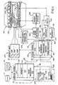
- Fig. 1 there is shown the major components of a preferred MRI system which incorporates the present invention.
- the operation of the system is controlled from an operator console 100 which includes a keyboard and control panel 102 and a display 104.
- the console 100 communicates through a link 116 with a separate computer system 107 that enables an operator to control the production and display of images on the screen 104.
- the computer system 107 includes a number of modules which communicate with each other through a backplane. These include an image processor module 106, a CPU module 108 and a memory module 113, known in the art as a frame buffer for storing image data arrays.
- the computer system 107 is linked to a disk storage 111 and a tape drive 112 for storage of image data and programs, and it communicates with a separate system control 122 through a high speed serial link 115.
- the system control 122 includes a set of modules connected together by a back plane 118. These include a CPU module 119 and a pulse generator module 121 which connects to the operator console 100 through a serial link 125. It is through this link 125 that the system control 122 receives commands from the operator which indicate the scan sequence that is to be performed.
- the pulse generator module 121 operates the system components to carry out the desired scan sequence. It produces data which indicates the timing, strength and shape of the RF pulses which are to be produced, and the timing of and length of the data acquisition window.
- the pulse generator module 121 connects to a set of gradient amplifiers 127, to indicate the timing and shape of the gradient pulses to be produced during the scan.
- the pulse generator module 121 also receives patient data from a physiological acquisition controller 129 that receives signals from sensors connected to the patient. One such signal is an ECG signal which is processed by the controller 129 to produce a cardiac trigger signal for the pulse generator module 121.
- the pulse generator module 121 also connects to a scan room interface circuit 133 which receives signals from various sensors associated with the condition of the patient and the magnet system. It is also through the scan room interface circuit 133 that a patient positioning system 134 receives commands to move the patient to the desired position for the scan.
- the gradient waveforms produced by the pulse generator module 121 are applied to a gradient amplifier system 127 comprised of G x , G y and G z amplifiers.
- Each gradient amplifier excites a corresponding gradient coil in an assembly generally designated 139 to produce the magnetic field gradients used for position encoding acquired signals.
- the gradient coil assembly 139 forms part of a magnet assembly 141 which includes a polarizing magnet 140 and a whole-body RF coil 152.
- a transceiver module 150 in the system control 122 produces pulses which are amplified by an RF amplifier 151 and coupled to the RIF coil 152 by a transmit/receive switch 154.
- the resulting signals radiated by the excited nuclei in the patient may be sensed by the same RF coil 152 and coupled through the transmit/receive switch 154 to a preamplifier 153.
- the amplified NMR signals are demodulated, filtered, and digitized in the receiver section of the transceiver 150.
- the transmit/receive switch 154 is controlled by a signal from the pulse generator module 121 to electrically connect the RF amplifier 151 to the coil 152 during the transmit mode and to connect the preamplifier 153 during the receive mode.
- the transmit/receive switch 154 also enables a separate RIF coil (for example, a head coil or surface coil) to be used in either the transmit or receive mode.
- the NMR signals picked up by the RF coil 152 are down converted by an RF reference signal and then digitized by the transceiver module 150.
- the digitized NMR signal is transferred to a memory module 160 in the system control 122.
- an array processor 161 operates to Fourier transform the data into an array of image data.
- This image data is conveyed through the serial link 115 to the computer system 107 where it is stored in the disk memory 111.
- this image data may be archived on the tape drive 112, or it may be further processed by the image processor 106 and conveyed to the operator console 100 and presented on the display 104.
- U.S. patent Nos. 4,952,877 and 4,992,736 for a more detailed description of the transceiver 150, reference is made to U.S. patent Nos. 4,952,877 and 4,992,736.
- an exemplary 3D gradient recalled echo pulse sequence employs an RF excitation pulse 300 which is applied to the subject in the presence of a G z , slab select gradient pulse 301 to produce transverse magnetization in a selected slab.
- a negative G z gradient pulse 304 followed by a positive G z gradient pulse 305 are produced by the G z gradient coils as taught in U.S. Pat. No. 4,731,583.
- the gradient pulse 304 has multiple amplitudes and it also provides phase encoding along the z axis direction. While the pulses 304 and 305 compensate for velocity along the z-axis, more complex gradient waveforms are also well known to those skilled in the art for compensating acceleration and even higher orders of motion.
- a phase encoding G y gradient pulse 306 is applied to the subject shortly after the application of the RF excitation pulse 300.
- a complete scan is comprised of a series of these pulse sequences in which the value of the G y phase encoding pulse is stepped through a series of, for example, 256 discrete phase encoding values to localize the position of the spins producing the NMR signal along the y-axis.
- Position along the x-axis is located by a G x gradient pulse 307 which is produced as the NMR gradient echo signal 303 is acquired and which frequency encodes the NMR signal 303.
- the G x readout gradient pulse 307 remains at a constant value during the acquisition of the NMR signal.
- gradient pulses 308 and 309 precede the gradient pulse 307 as taught in U.S. Pat. No. 4,731,583.
- the NMR signal 303 is acquired by the system transceiver 122 and digitized into a row of N x (e.g. 256) complex numbers which are stored in memory. For each combination of the (G y , G z ) phase encoding gradients an NMR signal 303 is produced, acquired, digitized and stored in a separate row of N x (e.g. 256) complex numbers. At the completion of the scan, therefore, a three-dimensional (N x ⁇ N y ⁇ N z ) array of k-space data is stored, where NY is the number of phase encoding steps along the y direction and N z is the number of phase encoding steps along the z direction. This array of k-space data may be used to reconstruct an image as described above.
- NMR imaging pulse sequences may be used and that the invention can be applied to both 2DFT and 3DFT acquisitions.
- the imaging pulse sequence of Fig. 2 is preferred for 3D coronary artery imaging which is the preferred application of the present invention.
- navigator echo signals are also acquired during the image data acquisition to measure both the displacement and the velocity of subject motion during the scan. This displacement and velocity information may be employed in a number of different ways to reduce the motion artifacts in the image reconstructed from the acquired k-space image data set.
- a conventional navigator pulse sequence is used to measure the location of the patient's diaphragm during each cardiac cycle.
- This navigator pulse sequence excites a column of spins located at the right side of the abdomen, and transecting the diaphragm near the dome of the liver using a two-dimensional rf excitation pulse.
- An NMR signal is acquired in the presence of a readout gradient (G z in the preferred embodiment) directed along the lengthwise dimension of the excited column, and N echo (e.g. 256) samples of the NMR navigator signal are Fourier transformed by the array processor 161.
- the two-dimensional excitation rf pulse is, for example, a 30 mm diameter excitation which produces a 900 flip angle, although other diameters or flip angles may also be excited.
- such two-dimensional rf pulses are produced in the presence of two gradient fields (G x and G y in the preferred embodiment) and the receiver low pass filter is set for a field of view (e.g. 260mm) along the excited column (z axis).
- the NMR signal is sampled at N echo points during a period of, for example, 4 msec. sample period.
- a reference navigator echo is acquired prior to the acquisition of image data.
- the reference navigator echo is usually acquired at the end of expiration because the respiratory motion is more stable and reproducible at this position.
- the displacement between the current diaphragm position and the reference diaphragm position can be measured using the auto-correlation and least mean-squares algorithms as described by Y. Wang et al, "Algorithms for Extracting Motion Information From Navigator Echoes", Magn. Reson. Med., 36:117-123, 1996.
- the diaphragm position can also be measured by using the linear phase shift algorithm disclosed in U.S. Pat. Appin. No. 08/980,192 filed November 26, 1997 by Thomas Kwok-Fah Foo and Kevin F. King.
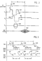
- This conventional navigator pulse sequence is used in a cardiac gated scan as depicted in Fig. 3.
- the QRS complex 320 of the ECG signal indicates the start of each R-R interval (i through i+n), during which segments 322 of NMR image data are acquired using the imaging pulse sequence of Fig. 2.
- each segment 322 samples a plurality of lines in k-space from one or more slabs through the patient's heart and the acquisitions continue until enough image data has been acquired to reconstruct one or more images.
- the navigator pulse sequence is performed twice during each cardiac cycle to measure the location of the patient's diaphragm just prior to each segment 322 acquisition as indicated at 324 and just after each segment acquisition as indicated at 326.
- the acquired navigator signals 324 and 326 are processed as described above to produce respective diaphragm positions D(i,l) and D(i,2) during each R-R interval i.
- navigator signals 324 and 326 can be acquired both prior to each segment 322 acquisition, or both after each segment 322 acquisition.
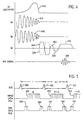
- a unique navigator pulse sequence is employed which directly measures both diaphragm position and velocity.
- This preferred navigator pulse sequence is depicted in Fig. 4, and is distinguished from the conventional navigator pulse sequence described above by the addition of a bi-polar, velocity encoding gradient 340 applied along the readout gradient axis (e.g. G z ).
- This velocity encoding gradient 340 is applied after the transverse magnetization of the column of spins produced by the two-dimensional rf excitation pulse 342 in the presence of two orthogonal gradients 344 and 346.
- a similar pulse sequence has been used for M-mode flow velocity measurements as described by C. J.
- the velocity encoding gradient 340 imposes a phase shift on this transverse magnetization which is proportional to the velocity of spin motion along the readout direction.
- This phase information is captured when a navigator NMR echo signal 348 is subsequently acquired in the presence of a readout gradient 350 that frequency encodes the acquired signal as a function of spin location along the readout gradient axis (e.g. G z ).
- a pair of readout gradient pulses 352 and 354 are applied just prior to the readout gradient pulse 350 to flow compensate the acquired signal as described in U.S. Patent No. 4,731,583.
- the navigator pulse sequence of Fig. 4 is repeated with the polarity of the velocity encoding gradient 340 reversed as indicated by dashed lines 356.
- Two complex navigator profiles are obtained after the inverse Fourier transform of these two navigator signals acquired at opposite velocity encoding polarities: NAV+ and NAV-,
- the position information is obtained by producing a magnitude profile from one or both complex navigator profiles.
- the velocity information is obtained by calculating the phase difference of these two complex navigator profiles.
- the velocity encoded navigator pulse sequence pair NAV+ and NAV- is performed during each cardiac cycle to indicate diaphragm location and velocity as each segment 322 is acquired.
- both NAV+ and NAV- are acquired immediately prior to each image segment 322 as indicated in Fig. 5 by dashed line 362.
- These navigator acquisitions could also be made just after each segment acquisition 322 as indicated at 360.
- the resulting diaphragm position and diaphragm velocity information are used in any of a number of methods to reduce artifacts in the images reconstructed from the acquired image data. Three methods will be described and the choice of which method is used depends on the particular clinical application.
- the first method for reducing image artifacts due to the measured position and velocity information is to reject image data that are acquired during certain conditions. More particularly, a position acceptance window is established and if the measured diaphragm position is outside this acceptance window, the acquired image data segment 322 is discarded. Similarly, a velocity acceptance threshold is established and if the absolute value of the measured diaphragm velocity exceeds this threshold, the acquired image data segment 322 is discarded. While this method ensures that corrupted image data is not used in the image reconstruction, the total scan time is increased because the discarded image segments 322 must be re-acquired under acceptable diaphragm motion conditions.
- the second method uses the measured position and velocity information to retrospectively correct the acquired image data.
- a positional displacement of the heart generates a linear phase error in the consecutive image echoes acquired in the R-R interval.
- the velocity of the heart generates a quadratic phase error in the consecutive echoes acquired in the R-R interval.
- This quadratic phase error is described in "Respiratory Blur in 3D Coronary MR Imaging", Magn, Reson. Med., 33:541-548 (1995) written by Yi Wang, et al.
- This quadratic phase error can be subtracted from the image data before image reconstruction using the navigator measurement of velocity.
- the third method uses the measured diaphragm position and velocity information to prospectively correct the acquired image data.
- the navigator signals are acquired before the image data segments 322 as indicated at 362.
- the phase corrections required to compensate for the positional displacement and velocity motion are calculated as described above for the second correction method.
- This phase correction is performed by applying to the NIVIR signal receiver in the transceiver module 150 a negated phase error immediately prior to the acquisition of the image data segments 322.
- the phase errors caused by respiratory motion are thus corrected in the received NIVIR signal prior to image reconstruction.
- This method is applicable only when the position and velocity measurement are both performed prior to the acquisition of image data segments 322.
- more than one correction method may be used during a scan.
- the first method may be used to discard some image data which is too corrupted to be corrected, and then method two or method three may be used to correct the phase of the acquired data.
Landscapes
- Physics & Mathematics (AREA)
- Health & Medical Sciences (AREA)
- Engineering & Computer Science (AREA)
- Cardiology (AREA)
- Radiology & Medical Imaging (AREA)
- Physiology (AREA)
- Power Engineering (AREA)
- Pulmonology (AREA)
- General Health & Medical Sciences (AREA)
- Nuclear Medicine, Radiotherapy & Molecular Imaging (AREA)
- Biophysics (AREA)
- Signal Processing (AREA)
- Life Sciences & Earth Sciences (AREA)
- High Energy & Nuclear Physics (AREA)
- Condensed Matter Physics & Semiconductors (AREA)
- General Physics & Mathematics (AREA)
- Magnetic Resonance Imaging Apparatus (AREA)
Applications Claiming Priority (2)
| Application Number | Priority Date | Filing Date | Title |
|---|---|---|---|
| US09/460,686 US6292684B1 (en) | 1999-12-14 | 1999-12-14 | Respiratory displacement and velocity measurement using navigator MRI echo signals |
| US460686 | 1999-12-14 |
Publications (3)
| Publication Number | Publication Date |
|---|---|
| EP1113288A2 EP1113288A2 (en) | 2001-07-04 |
| EP1113288A3 EP1113288A3 (en) | 2003-07-16 |
| EP1113288B1 true EP1113288B1 (en) | 2006-03-08 |
Family
ID=23829674
Family Applications (1)
| Application Number | Title | Priority Date | Filing Date |
|---|---|---|---|
| EP00311149A Expired - Lifetime EP1113288B1 (en) | 1999-12-14 | 2000-12-12 | Respiratory displacement and velocity measurement using navigator MRI echo signals |
Country Status (4)
| Country | Link |
|---|---|
| US (1) | US6292684B1 (enExample) |
| EP (1) | EP1113288B1 (enExample) |
| JP (1) | JP4773612B2 (enExample) |
| DE (1) | DE60026474T2 (enExample) |
Cited By (1)
| Publication number | Priority date | Publication date | Assignee | Title |
|---|---|---|---|---|
| WO2011104605A3 (en) * | 2010-02-23 | 2011-12-01 | University Of Cape Town | A method for compensating for respiratory motion in magnetic resonance imaging |
Families Citing this family (40)
| Publication number | Priority date | Publication date | Assignee | Title |
|---|---|---|---|---|
| US7127092B2 (en) * | 2000-04-26 | 2006-10-24 | Mayo Foundation For Medical Education And Research | Reduction of motion artifact in NMR images using spherical navigator signals |
| JP3891799B2 (ja) * | 2001-06-21 | 2007-03-14 | ジーイー・メディカル・システムズ・グローバル・テクノロジー・カンパニー・エルエルシー | Mri装置 |
| US6426990B1 (en) | 2001-06-28 | 2002-07-30 | General Electric Company | Methods and apparatus for coronary-specific imaging reconstruction |
| US6472872B1 (en) * | 2001-06-29 | 2002-10-29 | Mayo Foundation For Medical Education And Research | Real-time shimming of polarizing field in magnetic resonance system |
| US7561909B1 (en) * | 2002-09-16 | 2009-07-14 | The United States Of America As Represented By The Department Of Health And Human Services | MRI navigator methods and systems |
| US7993285B2 (en) * | 2002-11-05 | 2011-08-09 | Boston Scientific Scimed, Inc. | Medical device having flexible distal tip |
| US7103400B2 (en) * | 2002-11-08 | 2006-09-05 | Koninklijke Philips Electronics, N.V. | Artifact elimination in time-gated anatomical imaging |
| JP4133348B2 (ja) * | 2003-01-07 | 2008-08-13 | 株式会社日立メディコ | 核磁気共鳴を用いた検査装置 |
| JPWO2004080301A1 (ja) * | 2003-03-14 | 2006-06-08 | 株式会社日立メディコ | 磁気共鳴イメージング装置 |
| WO2006014260A2 (en) * | 2004-07-06 | 2006-02-09 | Mayo Foundation For Medical Education And Research | Magnetic resonance imaging of amyloid plaque |
| US7868884B2 (en) * | 2004-08-31 | 2011-01-11 | General Electric Company | System and method for generating a digital image of an internal anatomy of a person |
| US8352013B2 (en) * | 2005-01-18 | 2013-01-08 | Siemens Medical Solutions Usa, Inc. | Method and system for motion compensation in magnetic resonance (MR) imaging |
| DE102005023193B4 (de) * | 2005-05-19 | 2015-07-02 | Siemens Aktiengesellschaft | Verfahren zum Abbilden eines Untersuchungsvolumens in einem MR-Spektrometer |
| DE102005036515B4 (de) * | 2005-08-03 | 2015-07-09 | Siemens Aktiengesellschaft | Verfahren zur Planung einer Untersuchung in einer Magnetresonanzanlage |
| JP2007098026A (ja) * | 2005-10-07 | 2007-04-19 | Ge Medical Systems Global Technology Co Llc | 磁気共鳴イメージング装置 |
| JP5105848B2 (ja) * | 2006-02-06 | 2012-12-26 | 株式会社東芝 | 磁気共鳴イメージング装置および磁気共鳴イメージング装置における撮影条件設定方法 |
| CN100570393C (zh) * | 2006-02-06 | 2009-12-16 | 株式会社东芝 | 磁共振成像装置及磁共振成像方法 |
| US7642777B1 (en) | 2006-08-21 | 2010-01-05 | University Of Virginia Patent Foundation | Fast automatic linear off-resonance correction method for spiral imaging |
| JP4912808B2 (ja) * | 2006-09-22 | 2012-04-11 | ジーイー・メディカル・システムズ・グローバル・テクノロジー・カンパニー・エルエルシー | 磁気共鳴イメージング装置 |
| DE102006055933B4 (de) * | 2006-11-27 | 2010-04-08 | Siemens Ag | Verfahren zur Ermittlung einer Bewegung bei der Aufzeichnung von MR-Messdaten und Magnet-Resonanz-Gerät hierzu |
| US7826800B2 (en) * | 2006-11-27 | 2010-11-02 | Orthosoft Inc. | Method and system for determining a time delay between transmission and reception of an RF signal in a noisy RF environment using phase detection |
| JP5097406B2 (ja) * | 2007-01-22 | 2012-12-12 | ジーイー・メディカル・システムズ・グローバル・テクノロジー・カンパニー・エルエルシー | Mri装置 |
| JP4896763B2 (ja) * | 2007-02-19 | 2012-03-14 | 株式会社東芝 | 呼吸抑制部材および磁気共鳴映像装置 |
| US8417007B2 (en) * | 2007-12-10 | 2013-04-09 | Kabushiki Kaisha Toshiba | Magnetic resonance imaging apparatus and magnetic resonance imaging method |
| CN101721210B (zh) | 2008-10-15 | 2013-08-21 | 株式会社东芝 | 磁共振成像装置以及磁共振成像方法 |
| JP5454846B2 (ja) * | 2008-10-15 | 2014-03-26 | 株式会社東芝 | 磁気共鳴映像装置 |
| RU2013136488A (ru) * | 2011-01-05 | 2015-02-10 | Конинклейке Филипс Электроникс Н.В. | Способ и устройство детектирования и коррекции движения в данных позитронно-эмиссионной томографии в режиме списка с использованием синхронизированного сигнала |
| RU2014142029A (ru) * | 2012-03-19 | 2016-05-20 | Конинклейке Филипс Н.В. | Способ восстановления магнитно-резонансного изображения с обнаружением дыхательного движения во время дискретизации центральной и переферийной областей k-пространства |
| US8900225B2 (en) * | 2012-05-07 | 2014-12-02 | Biosense Webster (Israel) Ltd. | Automatic ablation tracking |
| EP2728371B1 (en) * | 2012-11-02 | 2022-07-27 | Universitätsklinikum Freiburg | Segmented 3D Cartesian MR data acquisition using a randomized sampling pattern for compressed sensing image reconstruction |
| JP6109598B2 (ja) * | 2013-02-26 | 2017-04-05 | 東芝メディカルシステムズ株式会社 | 磁気共鳴イメージング装置 |
| US9398855B2 (en) | 2013-05-30 | 2016-07-26 | Siemens Aktiengesellschaft | System and method for magnetic resonance imaging based respiratory motion correction for PET/MRI |
| JP5889841B2 (ja) * | 2013-07-08 | 2016-03-22 | 株式会社東芝 | 磁気共鳴映像装置 |
| JP2013198795A (ja) * | 2013-07-08 | 2013-10-03 | Toshiba Corp | 磁気共鳴映像装置 |
| JP5881793B2 (ja) * | 2014-09-24 | 2016-03-09 | 株式会社東芝 | 磁気共鳴映像装置 |
| US10132902B2 (en) * | 2015-05-26 | 2018-11-20 | The Board Of Trustees Of The Leland Stanford Junior University | Intrinsic navigation from velocity-encoding gradients in phase-contrast MRI |
| CN106539584B (zh) * | 2015-09-22 | 2020-08-04 | 上海联影医疗科技有限公司 | 磁共振成像方法及系统 |
| US11073584B2 (en) | 2018-09-06 | 2021-07-27 | Canon Medical Systems Corporation | Magnetic resonance imaging apparatus |
| CN109917315B (zh) | 2019-04-30 | 2021-09-28 | 上海联影医疗科技股份有限公司 | 磁共振成像扫描方法、装置、计算机设备和存储介质 |
| US11163029B2 (en) | 2019-08-14 | 2021-11-02 | GE Precision Healthcare LLC | MRI system with improved navigator |
Family Cites Families (11)
| Publication number | Priority date | Publication date | Assignee | Title |
|---|---|---|---|---|
| USRE32701E (en) | 1983-01-04 | 1988-06-21 | Wisconsin Alumni Research Foundation | NMR scanner with motion zeugmatography |
| JPS63164943A (ja) * | 1986-09-03 | 1988-07-08 | 株式会社日立製作所 | Nmrイメ−ジング方式 |
| US4937526A (en) * | 1988-11-23 | 1990-06-26 | Mayo Foundation For Medical Education And Research | Adaptive method for reducing motion and flow artifacts in NMR images |
| US5031624A (en) * | 1990-08-17 | 1991-07-16 | Wisconsin Alumni Research Foundation | Phase contrast, line-scanned method for NMR angiography |
| US5285158A (en) * | 1992-08-06 | 1994-02-08 | Wisconsin Alumni Research Foundation | NMR angiography using fast pulse sequences with preparatory pulses |
| DE69634976T2 (de) * | 1995-12-14 | 2006-04-20 | Koninklijke Philips Electronics N.V. | Verfahren und gerät zum erhitzen mit ultraschall, gesteuert durch bilderzeugung mit magnetischer resonanz |
| DE19607023A1 (de) * | 1996-02-24 | 1997-08-28 | Philips Patentverwaltung | MR-Verfahren mit reduzierten Bewegungsartefakten |
| CA2187964C (en) * | 1996-10-16 | 2005-02-01 | Kecheng Liu | Sliding interleaved motsa for magnetic resonance imaging |
| US5833609A (en) * | 1996-11-26 | 1998-11-10 | Picker International, Inc. | Rotating diffusion MR imaging reduced motion artifacts |
| US6043654A (en) * | 1997-11-14 | 2000-03-28 | Picker International, Inc. | Multi-volume slicing and interleaved phase-encoding acquisition for 3 D fast spin echo (FSE) |
| US6144874A (en) * | 1998-10-15 | 2000-11-07 | General Electric Company | Respiratory gating method for MR imaging |
-
1999
- 1999-12-14 US US09/460,686 patent/US6292684B1/en not_active Expired - Lifetime
-
2000
- 2000-12-12 EP EP00311149A patent/EP1113288B1/en not_active Expired - Lifetime
- 2000-12-12 DE DE60026474T patent/DE60026474T2/de not_active Expired - Lifetime
- 2000-12-13 JP JP2000378250A patent/JP4773612B2/ja not_active Expired - Fee Related
Cited By (2)
| Publication number | Priority date | Publication date | Assignee | Title |
|---|---|---|---|---|
| WO2011104605A3 (en) * | 2010-02-23 | 2011-12-01 | University Of Cape Town | A method for compensating for respiratory motion in magnetic resonance imaging |
| US8487616B2 (en) | 2010-02-23 | 2013-07-16 | University Of Cape Town | Method for compensating for respiratory motion in magnetic resonance imaging |
Also Published As
| Publication number | Publication date |
|---|---|
| JP4773612B2 (ja) | 2011-09-14 |
| DE60026474D1 (de) | 2006-05-04 |
| DE60026474T2 (de) | 2006-10-12 |
| US6292684B1 (en) | 2001-09-18 |
| EP1113288A3 (en) | 2003-07-16 |
| JP2001204712A (ja) | 2001-07-31 |
| EP1113288A2 (en) | 2001-07-04 |
Similar Documents
| Publication | Publication Date | Title |
|---|---|---|
| EP1113288B1 (en) | Respiratory displacement and velocity measurement using navigator MRI echo signals | |
| US6268730B1 (en) | Multi-slab multi-window cardiac MR imaging | |
| US6144874A (en) | Respiratory gating method for MR imaging | |
| US7209777B2 (en) | Method and apparatus for automated tracking of non-linear vessel movement using MR imaging | |
| US6393313B1 (en) | Producing a phase contrast MR image from a partial Fourier data acquisition | |
| US5363844A (en) | Breath-hold monitor for MR imaging | |
| EP1430327B1 (en) | Magnetic resonance angiography using floating table projection imaging | |
| US20020173715A1 (en) | Method for acquiring MRI data from a large field of view using continuous table motion | |
| US6518759B2 (en) | Motion correction of magnetic resonance images | |
| US6184682B1 (en) | Correction of MR images for motion artifacts using navigator echoes and autocorrection | |
| US7432706B2 (en) | Magnetic resonance imaging using blood flow navigation | |
| US7457655B2 (en) | Motion correction of magnetic resonance images using moments of spatial projections | |
| US7689263B1 (en) | Method and apparatus for acquiring free-breathing MR images using navigator echo with saturation RF pulse | |
| EP1227332B1 (en) | Acquisition of high-temporal free-breathing MR images | |
| EP1139114A2 (en) | Slice ordering method for breath-hold abdominal MR imaging | |
| US6310479B1 (en) | Magnetic resonance projection imaging of dynamic subjects | |
| CN112394311B (zh) | 具有改进的导航器的mri系统 | |
| JP2006519677A (ja) | 連続的テーブル移動を用いて時間分解mr画像を取得する方法 | |
| US6294913B1 (en) | Compensation of variations in polarizing magnetic field during magnetic resonance imaging | |
| US5810729A (en) | Method for measuring and adding limb angle indicia to MR images | |
| US7693569B1 (en) | Method and system of determining motion in a region-of-interest directly and independently of k-space trajectory | |
| US6377831B1 (en) | Real-time MR image subtraction and reconstruction | |
| US6288541B1 (en) | MRI measurement of blood vessel wall compliance | |
| EP1693680B1 (en) | Continuous table motion MRI involving phase correction | |
| US6278273B1 (en) | MR fluoroscopy with reverse-centric view acquisition |
Legal Events
| Date | Code | Title | Description |
|---|---|---|---|
| PUAI | Public reference made under article 153(3) epc to a published international application that has entered the european phase |
Free format text: ORIGINAL CODE: 0009012 |
|
| AK | Designated contracting states |
Kind code of ref document: A2 Designated state(s): AT BE CH CY DE DK ES FI FR GB GR IE IT LI LU MC NL PT SE TR |
|
| AX | Request for extension of the european patent |
Free format text: AL;LT;LV;MK;RO;SI |
|
| RIN1 | Information on inventor provided before grant (corrected) |
Inventor name: DU, YIPING P. Inventor name: MCVEIGH, ELLIOT R. |
|
| PUAL | Search report despatched |
Free format text: ORIGINAL CODE: 0009013 |
|
| AK | Designated contracting states |
Designated state(s): AT BE CH CY DE DK ES FI FR GB GR IE IT LI LU MC NL PT SE TR |
|
| AX | Request for extension of the european patent |
Extension state: AL LT LV MK RO SI |
|
| 17P | Request for examination filed |
Effective date: 20040116 |
|
| AKX | Designation fees paid |
Designated state(s): DE NL |
|
| GRAP | Despatch of communication of intention to grant a patent |
Free format text: ORIGINAL CODE: EPIDOSNIGR1 |
|
| GRAS | Grant fee paid |
Free format text: ORIGINAL CODE: EPIDOSNIGR3 |
|
| GRAA | (expected) grant |
Free format text: ORIGINAL CODE: 0009210 |
|
| AK | Designated contracting states |
Kind code of ref document: B1 Designated state(s): DE NL |
|
| REF | Corresponds to: |
Ref document number: 60026474 Country of ref document: DE Date of ref document: 20060504 Kind code of ref document: P |
|
| PLBE | No opposition filed within time limit |
Free format text: ORIGINAL CODE: 0009261 |
|
| STAA | Information on the status of an ep patent application or granted ep patent |
Free format text: STATUS: NO OPPOSITION FILED WITHIN TIME LIMIT |
|
| 26N | No opposition filed |
Effective date: 20061211 |
|
| PGFP | Annual fee paid to national office [announced via postgrant information from national office to epo] |
Ref country code: DE Payment date: 20121231 Year of fee payment: 13 |
|
| PGFP | Annual fee paid to national office [announced via postgrant information from national office to epo] |
Ref country code: NL Payment date: 20121225 Year of fee payment: 13 |
|
| REG | Reference to a national code |
Ref country code: DE Ref legal event code: R119 Ref document number: 60026474 Country of ref document: DE |
|
| REG | Reference to a national code |
Ref country code: NL Ref legal event code: V1 Effective date: 20140701 |
|
| REG | Reference to a national code |
Ref country code: DE Ref legal event code: R119 Ref document number: 60026474 Country of ref document: DE Effective date: 20140701 |
|
| PG25 | Lapsed in a contracting state [announced via postgrant information from national office to epo] |
Ref country code: DE Free format text: LAPSE BECAUSE OF NON-PAYMENT OF DUE FEES Effective date: 20140701 Ref country code: NL Free format text: LAPSE BECAUSE OF NON-PAYMENT OF DUE FEES Effective date: 20140701 |