EP1113177A2 - Magnetically levitated pump - Google Patents
Magnetically levitated pump Download PDFInfo
- Publication number
- EP1113177A2 EP1113177A2 EP00128516A EP00128516A EP1113177A2 EP 1113177 A2 EP1113177 A2 EP 1113177A2 EP 00128516 A EP00128516 A EP 00128516A EP 00128516 A EP00128516 A EP 00128516A EP 1113177 A2 EP1113177 A2 EP 1113177A2
- Authority
- EP
- European Patent Office
- Prior art keywords
- rotative
- pump
- magnetic
- electromagnet
- magnetically levitated
- Prior art date
- Legal status (The legal status is an assumption and is not a legal conclusion. Google has not performed a legal analysis and makes no representation as to the accuracy of the status listed.)
- Granted
Links
Images




Classifications
-
- F—MECHANICAL ENGINEERING; LIGHTING; HEATING; WEAPONS; BLASTING
- F04—POSITIVE - DISPLACEMENT MACHINES FOR LIQUIDS; PUMPS FOR LIQUIDS OR ELASTIC FLUIDS
- F04D—NON-POSITIVE-DISPLACEMENT PUMPS
- F04D29/00—Details, component parts, or accessories
- F04D29/04—Shafts or bearings, or assemblies thereof
- F04D29/046—Bearings
- F04D29/048—Bearings magnetic; electromagnetic
-
- A—HUMAN NECESSITIES
- A61—MEDICAL OR VETERINARY SCIENCE; HYGIENE
- A61M—DEVICES FOR INTRODUCING MEDIA INTO, OR ONTO, THE BODY; DEVICES FOR TRANSDUCING BODY MEDIA OR FOR TAKING MEDIA FROM THE BODY; DEVICES FOR PRODUCING OR ENDING SLEEP OR STUPOR
- A61M60/00—Blood pumps; Devices for mechanical circulatory actuation; Balloon pumps for circulatory assistance
- A61M60/10—Location thereof with respect to the patient's body
- A61M60/122—Implantable pumps or pumping devices, i.e. the blood being pumped inside the patient's body
- A61M60/165—Implantable pumps or pumping devices, i.e. the blood being pumped inside the patient's body implantable in, on, or around the heart
-
- A—HUMAN NECESSITIES
- A61—MEDICAL OR VETERINARY SCIENCE; HYGIENE
- A61M—DEVICES FOR INTRODUCING MEDIA INTO, OR ONTO, THE BODY; DEVICES FOR TRANSDUCING BODY MEDIA OR FOR TAKING MEDIA FROM THE BODY; DEVICES FOR PRODUCING OR ENDING SLEEP OR STUPOR
- A61M60/00—Blood pumps; Devices for mechanical circulatory actuation; Balloon pumps for circulatory assistance
- A61M60/20—Type thereof
- A61M60/205—Non-positive displacement blood pumps
- A61M60/216—Non-positive displacement blood pumps including a rotating member acting on the blood, e.g. impeller
- A61M60/237—Non-positive displacement blood pumps including a rotating member acting on the blood, e.g. impeller the blood flow through the rotating member having mainly axial components, e.g. axial flow pumps
-
- A—HUMAN NECESSITIES
- A61—MEDICAL OR VETERINARY SCIENCE; HYGIENE
- A61M—DEVICES FOR INTRODUCING MEDIA INTO, OR ONTO, THE BODY; DEVICES FOR TRANSDUCING BODY MEDIA OR FOR TAKING MEDIA FROM THE BODY; DEVICES FOR PRODUCING OR ENDING SLEEP OR STUPOR
- A61M60/00—Blood pumps; Devices for mechanical circulatory actuation; Balloon pumps for circulatory assistance
- A61M60/40—Details relating to driving
- A61M60/403—Details relating to driving for non-positive displacement blood pumps
- A61M60/419—Details relating to driving for non-positive displacement blood pumps the force acting on the blood contacting member being permanent magnetic, e.g. from a rotating magnetic coupling between driving and driven magnets
-
- A—HUMAN NECESSITIES
- A61—MEDICAL OR VETERINARY SCIENCE; HYGIENE
- A61M—DEVICES FOR INTRODUCING MEDIA INTO, OR ONTO, THE BODY; DEVICES FOR TRANSDUCING BODY MEDIA OR FOR TAKING MEDIA FROM THE BODY; DEVICES FOR PRODUCING OR ENDING SLEEP OR STUPOR
- A61M60/00—Blood pumps; Devices for mechanical circulatory actuation; Balloon pumps for circulatory assistance
- A61M60/40—Details relating to driving
- A61M60/403—Details relating to driving for non-positive displacement blood pumps
- A61M60/422—Details relating to driving for non-positive displacement blood pumps the force acting on the blood contacting member being electromagnetic, e.g. using canned motor pumps
-
- A—HUMAN NECESSITIES
- A61—MEDICAL OR VETERINARY SCIENCE; HYGIENE
- A61M—DEVICES FOR INTRODUCING MEDIA INTO, OR ONTO, THE BODY; DEVICES FOR TRANSDUCING BODY MEDIA OR FOR TAKING MEDIA FROM THE BODY; DEVICES FOR PRODUCING OR ENDING SLEEP OR STUPOR
- A61M60/00—Blood pumps; Devices for mechanical circulatory actuation; Balloon pumps for circulatory assistance
- A61M60/50—Details relating to control
- A61M60/508—Electronic control means, e.g. for feedback regulation
-
- A—HUMAN NECESSITIES
- A61—MEDICAL OR VETERINARY SCIENCE; HYGIENE
- A61M—DEVICES FOR INTRODUCING MEDIA INTO, OR ONTO, THE BODY; DEVICES FOR TRANSDUCING BODY MEDIA OR FOR TAKING MEDIA FROM THE BODY; DEVICES FOR PRODUCING OR ENDING SLEEP OR STUPOR
- A61M60/00—Blood pumps; Devices for mechanical circulatory actuation; Balloon pumps for circulatory assistance
- A61M60/80—Constructional details other than related to driving
- A61M60/802—Constructional details other than related to driving of non-positive displacement blood pumps
- A61M60/818—Bearings
- A61M60/82—Magnetic bearings
- A61M60/822—Magnetic bearings specially adapted for being actively controlled
-
- F—MECHANICAL ENGINEERING; LIGHTING; HEATING; WEAPONS; BLASTING
- F04—POSITIVE - DISPLACEMENT MACHINES FOR LIQUIDS; PUMPS FOR LIQUIDS OR ELASTIC FLUIDS
- F04D—NON-POSITIVE-DISPLACEMENT PUMPS
- F04D13/00—Pumping installations or systems
- F04D13/02—Units comprising pumps and their driving means
- F04D13/021—Units comprising pumps and their driving means containing a coupling
- F04D13/024—Units comprising pumps and their driving means containing a coupling a magnetic coupling
- F04D13/026—Details of the bearings
-
- F—MECHANICAL ENGINEERING; LIGHTING; HEATING; WEAPONS; BLASTING
- F04—POSITIVE - DISPLACEMENT MACHINES FOR LIQUIDS; PUMPS FOR LIQUIDS OR ELASTIC FLUIDS
- F04D—NON-POSITIVE-DISPLACEMENT PUMPS
- F04D13/00—Pumping installations or systems
- F04D13/02—Units comprising pumps and their driving means
- F04D13/021—Units comprising pumps and their driving means containing a coupling
- F04D13/024—Units comprising pumps and their driving means containing a coupling a magnetic coupling
- F04D13/027—Details of the magnetic circuit
-
- F—MECHANICAL ENGINEERING; LIGHTING; HEATING; WEAPONS; BLASTING
- F04—POSITIVE - DISPLACEMENT MACHINES FOR LIQUIDS; PUMPS FOR LIQUIDS OR ELASTIC FLUIDS
- F04D—NON-POSITIVE-DISPLACEMENT PUMPS
- F04D13/00—Pumping installations or systems
- F04D13/02—Units comprising pumps and their driving means
- F04D13/06—Units comprising pumps and their driving means the pump being electrically driven
- F04D13/0666—Units comprising pumps and their driving means the pump being electrically driven the motor being of the plane gap type
-
- F—MECHANICAL ENGINEERING; LIGHTING; HEATING; WEAPONS; BLASTING
- F16—ENGINEERING ELEMENTS AND UNITS; GENERAL MEASURES FOR PRODUCING AND MAINTAINING EFFECTIVE FUNCTIONING OF MACHINES OR INSTALLATIONS; THERMAL INSULATION IN GENERAL
- F16C—SHAFTS; FLEXIBLE SHAFTS; ELEMENTS OR CRANKSHAFT MECHANISMS; ROTARY BODIES OTHER THAN GEARING ELEMENTS; BEARINGS
- F16C32/00—Bearings not otherwise provided for
- F16C32/04—Bearings not otherwise provided for using magnetic or electric supporting means
- F16C32/0406—Magnetic bearings
- F16C32/044—Active magnetic bearings
-
- A—HUMAN NECESSITIES
- A61—MEDICAL OR VETERINARY SCIENCE; HYGIENE
- A61M—DEVICES FOR INTRODUCING MEDIA INTO, OR ONTO, THE BODY; DEVICES FOR TRANSDUCING BODY MEDIA OR FOR TAKING MEDIA FROM THE BODY; DEVICES FOR PRODUCING OR ENDING SLEEP OR STUPOR
- A61M60/00—Blood pumps; Devices for mechanical circulatory actuation; Balloon pumps for circulatory assistance
- A61M60/10—Location thereof with respect to the patient's body
- A61M60/122—Implantable pumps or pumping devices, i.e. the blood being pumped inside the patient's body
- A61M60/126—Implantable pumps or pumping devices, i.e. the blood being pumped inside the patient's body implantable via, into, inside, in line, branching on, or around a blood vessel
- A61M60/148—Implantable pumps or pumping devices, i.e. the blood being pumped inside the patient's body implantable via, into, inside, in line, branching on, or around a blood vessel in line with a blood vessel using resection or like techniques, e.g. permanent endovascular heart assist devices
-
- F—MECHANICAL ENGINEERING; LIGHTING; HEATING; WEAPONS; BLASTING
- F16—ENGINEERING ELEMENTS AND UNITS; GENERAL MEASURES FOR PRODUCING AND MAINTAINING EFFECTIVE FUNCTIONING OF MACHINES OR INSTALLATIONS; THERMAL INSULATION IN GENERAL
- F16C—SHAFTS; FLEXIBLE SHAFTS; ELEMENTS OR CRANKSHAFT MECHANISMS; ROTARY BODIES OTHER THAN GEARING ELEMENTS; BEARINGS
- F16C2316/00—Apparatus in health or amusement
- F16C2316/10—Apparatus in health or amusement in medical appliances, e.g. in diagnosis, dentistry, instruments, prostheses, medical imaging appliances
- F16C2316/18—Pumps for pumping blood
-
- F—MECHANICAL ENGINEERING; LIGHTING; HEATING; WEAPONS; BLASTING
- F16—ENGINEERING ELEMENTS AND UNITS; GENERAL MEASURES FOR PRODUCING AND MAINTAINING EFFECTIVE FUNCTIONING OF MACHINES OR INSTALLATIONS; THERMAL INSULATION IN GENERAL
- F16C—SHAFTS; FLEXIBLE SHAFTS; ELEMENTS OR CRANKSHAFT MECHANISMS; ROTARY BODIES OTHER THAN GEARING ELEMENTS; BEARINGS
- F16C2360/00—Engines or pumps
- F16C2360/44—Centrifugal pumps
Definitions
- the present invention relates to magnetically levitated (maglev) pumps. More specifically, the present invention relates to those corresponding to a cleanpump employing a magnetic bearing and used for medical equipment such as artificial heart.
- Figs. 8A and 8B show a conventional maglev pump. More specifically, Fig. 8A is a vertical cross section thereof and Fig. 8B is a cross section taken along a line XIIIB-XIIIB of Fig. 8A. Fig. 9 is a cross section taken along a line IX-IX of Fig. 8A. Fig. 10 is a cross section taken along a line X-X of Fig. 8A.
- a maglev pump 1 includes a motor portion 10, a pump portion 20 and a magnetic bearing portion 30.
- a casing 21 accommodates a pump chamber 22 in which an impeller 23 rotates.
- Impeller 23 has a plurality of vanes 27 spirally provided, as shown in Fig. 8B.
- Casing 21 is formed of a cylindrical, non-magnetic member and impeller 23 includes a non-magnetic member 25 having a permanent magnet 24 configuring a non-controlled magnetic bearing and a soft magnetic member 26 corresponding to a rotor of a controlled magnetic bearing.
- Permanent magnet 24 is divided in a circumferential direction of impeller 23 and magnets adjacent to each other are magnetized to have opposite magnetic poles.
- Rotor 12 Opposite to the side of impeller 23 provided with permanent magnet 24, external to pump chamber 22 there is provided a disk rotor 12 supported by a shaft 11. Rotor 12 is rotatably driven by a motor 13. Rotor 12 is provided with the same number of permanent magnets 14 as impeller 23 that face permanent magnet 24 of impeller 23 to provide attraction. Adjacent permanent magnets 14 are magnetized to have opposite magnetic poles.
- Electromagnet 31 and the position sensor allow balance with the attraction of permanent magnets 24 and 14 to hold impeller 23 at the center of pump chamber 22.
- maglev pump 1 thus configured, attraction acts between permanent magnet 14 embedded in rotor 12 and permanent magnet 24 provided in impeller 23, axially in one direction. This attraction is exploited to provide magnetic-coupling to rotatably drive impeller 23 and obtain radial supporting-stiffness. To match it to this attraction, a flow of current is passed through a coil of C-shaped electromagnet 31, which in turn attracts impeller 23 axially in the other direction to levitate impeller 23. As rotor 12 is rotatably driven by motor 13, permanent magnets 14 and 24 provide magnetic-coupling, impeller 23 rotates and a fluid is sucked through an inlet 60 and discharged through an outlet 70 (see Fig. 8B). Impeller 23 is accommodated in casing 21 and thus isolated from rotor 12 and it is also not contaminated by electromagnet 31. Thus, maglev pump 1 delivers fluid (blood if it is used as a blood pump) held clean.
- a conventional maglev blood pump has electromagnet 31 with an arcuate yoke 41 and pairs of magnetic poles 42 and 43, 44 and 45, and 46 and 47 each arranged radially.
- maglev pump 1 as shown in Figs. 8A and 8B is used as a blood pump for an artificial heart, it is implanted in a body or used adjacent thereto. As such, it cannot be supplied with energy constantly from an external power supply. Typically, it is supplied with energy obtained from a mobile battery or a battery implanted in the body. As such, to use it for a long term, energy consumption must be minimized. Furthermore, if it is used for human body, it is required to have a small size and it also must be taken great care of to be reliable.
- maglev pump 1 however, as shown in Figs. 9 and 10, has each electromagnet with magnetic poles arranged radially. As such, the space for accommodating the coil cannot be effectively obtained. As such, magnetic bearing portion 30 must be disadvantageously increased in size to provide an additional space for the coil to reduce the power consumption of the electromagnet.
- maglev pump 1 has electromagnet 31 with an arcuate yoke. This makes it difficult to wind the coil and also hardly ensures insulation resistance between the coil and the yoke.
- maglev pump 1 has a partition corresponding to casing 21 of plastic material, ceramic material or non-magnetic metal material provided between soft magnetic member 26 of impeller 23 in pump chamber 22 and electromagnet 31 of magnetic bearing portion 30 and between soft magnetic member 26 of impeller 23 and position sensor 32 detecting the position of impeller 23.
- impeller 23 and electromagnet 31 are spaced far apart from each other.
- to levitate impeller 23 electromagnet 31 is required to pass a large amount of current.
- the sensor sensitivity also degrades as impeller 23 and position sensor 32 are spaced far apart from each other.
- the partition is less durable and can thus not be used for a long term. If the partition is formed of metal material and position sensor 32 is a magnetic sensor, then it has eddy current generated internal thereto to result in a loss and it also degrades the sensor sensitivity as it spaces position sensor 32 apart from a target.
- the present invention mainly contemplates a maglev pump capable of miniaturizing a magnetic bearing portion.
- the present invention also contemplates a maglev pump capable of reducing the distance between an electromagnet and an impeller and also reducing the distance between a sensor and the impeller to reduce the electromagnet's coil current and enhance the sensitivity of the sensor output.
- the present invention generally provides a maglev pump wherein a pump portion is provided with a rotative portion internal to a casing, the rotative portion is coupled with a rotation driving portion physically out of contact therewith and it is also supported by a controlled, magnetic bearing portion physically out of contact therewith, the rotative portion is rotated by the rotation driving portion to discharge fluid, a position sensor detects the position of the rotative portion in levitation and in response to the output of the position detection portion the controlled magnetic bearing portion is controlled, wherein the magnetic bearing portion is configured of a plurality of electromagnets formed of a magnetic pole, a yoke and a coil and the electromagnet has magnetic S and N poles each with at least the yoke and coil arranged circumferentially.
- a magnetic bearing includes electromagnets each having a magnetic pole and a yoke that are arranged circumferentially. This ensures a large space for winding a coil without increasing the space for the magnetic bearing portion or increasing the size of the pump. Since the coil can be accommodated in such a large space, the electromagnet coil can have an increased winding count and an increased wire diameter and consequently its power consumption can be reduced. Furthermore, the electromagnet can have a yoke in the form of a cylinder or a prism to facilitate winding a coil and thus readily ensure the insulation withstand voltage between the coil and the yoke.
- the electromagnet has a pair of magnetic poles circumferentially arranged and the electromagnet has a pair of magnetic poles radially arranged.
- the rotative portion is provided in a form of a disk having a side facing the rotation driving portion and provided with a permanent magnet circumferentially arranged and the rotative portion and the rotation driving portion are magnetically coupled together physically out of contact with each other, and the electromagnet has three pairs of magnetic S and N poles.
- the present invention in another aspect provides a maglev pump wherein a pump portion is provided with a rotative portion internal to a casing, the rotative portion is coupled with a rotation driving portion physically out of contact therewith and it is also supported by a controlled, magnetic bearing portion physically out of contact therewith, the rotative portion is rotated by the rotation driving portion to discharge fluid, a position sensor detects the position of the rotative portion in levitation and in response to the output of the position detection portion the controlled magnetic bearing portion is controlled, wherein the magnetic bearing portion includes a plurality of electromagnets each directly facing the rotative portion or the position detection portion includes a magnetic sensor directly facing the rotative portion.
- the magnetic beating portion can have a plurality of electromagnets directly facing a rotative portion or a magnetic sensor directly facing the rotative portion to reduce the distance between the rotative portion and the electromagnets or the magnetic sensor corresponding to a plane in which the electromagnetic force of the magnetic bearing acts.
- the pump can be levitated with a reduced amount of current flowing through an electromagnet coil for generating electromagnetic force to levitate the same, which is advantageous when the present pump is used as a blood pump since current consumption is one of its significant issues.
- the position sensor can be enhanced in sensitivity.
- the position detection portion includes a core formed of a soft magnetic material and a coil wound around the core.
- any of the electromagnet and the position detection portion is fixed to the casing by any of welding, brazing, press-fitting, pressure-welding, shrink-fitting and bonding or a combination thereof.
- the rotative portion is provided in the form of a disk having a side facing the rotation driving portion and having a first permanent magnet circumferentially arranged and the rotation driving portion has a second permanent magnet circumferentially arranged to face the first permanent magnet, the first and second permanent magnets achieving magnetic-coupling to couple together the rotative portion and the rotation driving portion physically out of contact with each other, and the pump portion has an internal surface coated with heparin.
- maglev pump in one embodiment of the present invention.
- the maglev pump is configured of a motor portion 10, a pump portion 20 and a magnetic bearing portion 40.
- a casing 21 houses a pump chamber 22 in which an impeller 23 rotates.
- Impeller 23 has a plurality of vanes 27 provided spirally, as shown in Fig. 1B.
- Casing 21 is formed of plastic, ceramic, metal or the like, although magnetic material cannot be used for casing 21 corresponding to a partition located between pump portion 20 and motor portion 10 and that located between pump portion 20 and magnetic bearing portion 40 and non-magnetic material is thus used to form those partitions.
- Impeller 23 includes a non-magnetic member 25 having a permanent magnet 24 configuring a non-controlled magnetic bearing, and a soft magnetic member 26 corresponding to a rotor of a controlled magnetic bearing. Permanent magnet 24 is divided in a circumferential direction of impeller 23 and adjacent permanent magnets are magnetized to have opposite magnetic poles.
- a hatched portion corresponds to a soft magnetic material and the remaining portion corresponds to a non-magnetic material.
- the soft magnetic material is preferably, e.g., highly corrosive-resistant, ferritic stainless steel (corresponding to JIS G4303 SUS447J1 and JIS G4303 SUS444) and the non-magnetic material is preferably, e.g., highly corrosive-resistant, austenitic stainless steel (corresponding to SUS316L or the like), or titanium alloy, pure titanium or the like.
- Rotor 12 Opposite to the side of impeller 23 provided with permanent magnet 24, external to the pump chamber there is provided a rotor 12 supported by a shaft 11. Rotor 12 is rotatably driven by a motor 13. Rotor 12 is provided with the same number of permanent magnets 14 as impeller 23 that face permanent magnet 24 of impeller 23 to provide attraction. Permanent magnets 14 adjacent to each other are magnetized to have opposite magnetic poles.
- Motor portion 10 is a synchronous motor including a DC brushless motor, an asynchronous motor including an induction motor, or the like, although any type of motor may be used.
- Electromagnet 111 and position sensor 62 are provided in magnetic bearing portion 40. Electromagnet 111 and position sensor 62 allow balance with the attraction of permanent magnets 24 and 14 to hold impeller 23 at the center of the pump chamber.
- Fig. 1A shows a single electromagnet 111 configured of a magnetic pole 51, an electromagnet yoke 71, an electromagnet coil 81 and an electromagnet backplate 91, although magnetic bearing portion 40 has three electromagnets arranged circumferentially. Furthermore, as shown in Fig. 2, sensors 61, 62 and 63 are arranged between their respective pairs of magnetic poles 51 and 52, 53 and 54, and 55 and 56. Sensors 61 to 63 are typically a magnetic sensor, such as an eddy-current sensor, a reluctance sensor, or the like.
- electromagnet yokes 71 to 76 each has a cylindrical shape, with electromagnet coils 81 to 86 wound therearound, respectively.
- Circumferentially arranging magnetic poles 51-56 can increase a space for accommodating electromagnet coils 81 to 86 that can be housed in magnetic bearing portion 40. Furthermore, providing electromagnet yokes 71 to 76 in the form of a cylinder can facilitate winding electromagnet coils 81 to 86 around electromagnet yokes 71 to 76. Furthermore, electromagnet yokes 71 to 76 having a simple shape ensures reliable isolation from electromagnet coils 81 to 86.
- electromagnet yokes 71 to 76 are provided in the form of a cylinder, they may be provided in the form of a prism. Furthermore, while in Figs. 2 and 3 electromagnet yokes 71 to 76 and electromagnet coils 81 to 86 are arranged on a single circumference, they may not be arranged on a single circumference so that an accommodating space can be effectively ensured.
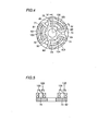
- Figs. 4 and 5 show another embodiment of the present invention, and Fig. 4 shows an exemplary arrangement of a magnetic pole and a coil and Fig. 5 is a cross section taken along line IV-IV of Fig. 4.
- electromagnet coils 81 to 86 and electromagnet yokes are arranged circumferentially, as similarly in Fig. 3, although pairs of magnetic poles 101 and 102, 103 and 104, and 105 and 106 are each arranged radially.
- magnetic pole 105, electromagnet yoke 75, electromagnet backplate 92, electromagnet yoke 76 and magnetic pole 106 configure a single C-shaped electromagnet.
- the embodiment shown in Figs. 4 and 5 also has an electromagnet yoke in the form of a cylinder to facilitate winding electromagnet coils 81 to 86, although the yoke is not limited to the cylinder and it may for example be a prism.
- the present embodiment is as effective as the embodiment shown in Figs. 1A-3.
- Figs. 6A and 6B show another embodiment of the present invention, and Fig. 6A is a vertical cross section and Fig. 6B is a cross section taken along line XIB-XIB of Fig. 6A.
- a magnetic bearing portion 120 includes an electromagnet 121 having a core 122 and a position sensor 124 having a core 125 and cores 122 and 125 are partially buried in casing 21 formed of a non-magnetic material and providing a partition between magnetic bearing portion 120 and pump portion 20.
- Core 122 has a coil 123 wound therearound and core 125 has a coil 126 wound therearound.
- electromagnet 121 and position sensor 124 have their respective ends exposed in pump chamber 22. Electromagnet 121 and casing 21 of pump chamber 22 are welded, brazed, press-fit, pressure-welded, shrink-fit or bonded together, or jointed together by a combination of those techniques to seal the interior and exterior of pump chamber 22.
- pump chamber 2 can have its interior entirely coated with heparin serving as an anticoagulant to prevent thrombus formation to allow the pump to be used as a blood transporting pump.
- heparin coating effectively constrains activation of coagulation system, protects platelets, constrains activation, activation of inflammation system, activation of fibrinolysis system, and the like.
- electromagnet 121 and position sensor 124 have their respective ends exposed in pump chamber 22 to directly face impeller 23. This can reduce the distance between soft magnetic member 25 of impeller 23 in pump chamber 22 and position sensor 124 detecting the position of the impeller. As a result, impeller 23 can be levitated with a small amount of current flowing through the coil of electromagnet 21 and position sensor 124 can also be enhanced in sensitivity.
- Fig. 7 is a block diagram showing a controller for driving a maglev pump of the present invention.
- a controller 200 includes a function provided to control the position of the impeller, a function provided to control the running torque of the impeller, a function employing the function controlling the impeller position, to alter in pump chamber 22 the position of impeller 23 in levitation, a function provided to measure the current of motor 13, and a function provided to calculate a fluid viscosity by referring to a variance of the current of motor 13 measured when the position of impeller 23 in levitation is changed via the function controlling the impeller position in levitation.
- controller 200 includes a controller body 201, a motor driver 202, and a control portion 203 for controlling the impeller position.
- Motor driver 202 outputs a level of voltage corresponding to a motor rotation rate output from controller body 201, to rotate motor 13.
- control portion 203 for controlling the impeller position maintains the impeller position in levitation output from controller body 201, by controlling the current or voltage flowing through the Fig. 1A electromagnet 111 or the Fig. 6A electromagnet 121.
- position sensor 24 output a result of detection, which is in turn input to control portion 203 for controlling the impeller position, to control the current flowing through electromagnet 111 or 121, to control the translation of impeller 23 in the direction of the central axis (an axis z) and the rotation of impeller 23 around axes x and y orthogonal to the central axis (axis z).
- the position sensor 61-63 or 124 output may be input to controller body 201, which may in turn output a value of voltage or current applied to electromagnet 111 or 121.
- Controller body 201 includes a storage portion (ROM) 204, a CPU 205, a display portion 210 and an input portion 207.
- Display portion 210 includes a set delivery rate (SDR) display portion 211, an executed delivery rate (EDR) display portion 212, a set delivery output (SDO) display portion 213, an executed delivery pressure (EDP) display portion 214, a fluid temperature (FT) display portion 215, a fluid viscosity (FV) display portion 216, and an impeller rotation rate (IRR) display portion 217.
- input portion 207 includes an SDR input portion 208 and an SDP input portion 209.
- Controller body 201 includes a data storage portion storing data of a relationship between fluid viscosity and motor current variance, corresponding to a previously obtained relationship between fluid viscosity and motor current variance depending on positional variance of the impeller in levitation (variance in motor drive current), or a relationship expression calculated from the data related to such relationship (for example data of a correlation expression or data of an expression of viscosity calculation), and the function provided for calculation of fluid viscosity calculates fluid viscosity from the data stored in storage portion 24 and the variance of the current through motor 13 obtained when the impeller 23 position in levitation is changed via the function controlling the impeller position in levitation.
- controller body 201 at storage portion 204 stores data related to a relationship between fluid viscosity and motor current variance corresponding to a previously obtained relationship between fluid viscosity and motor current variance depending on positional change of the impeller in levitation, or correlation data calculated from the data related to such relationship (also serving as data of an expression for viscosity calculation).
- a magnetic bearing includes electromagnets each having a magnetic pole and a yoke that are arranged circumferentially. This ensures a large space for winding a coil without increasing the space for the magnetic bearing portion or increasing the size of the pump. Since the coil can be accommodated in such a large space, the electromagnet coil can have an increased winding count and an increased wire diameter and consequently its power consumption can be reduced. Furthermore, the electromagnet can have a yoke in the form of a cylinder or a prism to facilitate winding a coil and thus readily ensure the insulation withstand voltage between the coil and the yoke.
- the magnetic bearing portion can have a plurality of electromagnets directly facing a rotative portion to reduce the distance between the rotative portion and the electromagnets corresponding to a plane in which the electromagnetic force of the magnetic bearing acts.
- the impeller can be levitated with a reduced amount of current flowing through an electromagnet coil for generating electromagnetic force to levitate the impeller, which is advantageous when the present pump is used as a blood pump since current consumption is one of its significant issues.
- the position sensor detecting the impeller position and the impeller can be less distant from each other to enhance the sensitivity of the position sensor.
Landscapes
- Engineering & Computer Science (AREA)
- Health & Medical Sciences (AREA)
- Heart & Thoracic Surgery (AREA)
- Mechanical Engineering (AREA)
- Cardiology (AREA)
- Life Sciences & Earth Sciences (AREA)
- Biomedical Technology (AREA)
- Hematology (AREA)
- Anesthesiology (AREA)
- Animal Behavior & Ethology (AREA)
- General Health & Medical Sciences (AREA)
- Public Health (AREA)
- Veterinary Medicine (AREA)
- General Engineering & Computer Science (AREA)
- Physics & Mathematics (AREA)
- Electromagnetism (AREA)
- Structures Of Non-Positive Displacement Pumps (AREA)
- Magnetic Bearings And Hydrostatic Bearings (AREA)
Abstract
Description
Claims (15)
- A magnetically levitated pump comprising:a pump portion (20) having a rotative portion (23) provided in a casing (21) and rotated to discharge fluid;a rotation driving portion (10) physically out of contact with said rotating portion, coupled with said rotative portion through magnetic force to rotatably drive said rotative portion;a position detection portion (62) detecting a position of said rotative portion in levitation; anda controlled magnetic bearing portion (40) physically out of contact with said rotative portion, supporting said rotative portion in response to an output corresponding to a result of detection provided by said position detection portion,wherein said magnetic bearing portion is configured of a plurality of electromagnets (111) formed of a magnetic pole (51-56), a yoke (71-76) and a coil (81-86), said electromagnet having each of magnetic S and N poles with at least said yoke and coil arranged circumferentially.
- The magnetically levitated pump of claim 1, wherein said electromagnet (111) has a pair of magnetic poles (51-56) arranged circumferentially.
- The magnetically levitated pump of claim 1, wherein said electromagnet has a pair of magnetic poles (51-56) arranged radially.
- The magnetically levitated pump of claim 1, wherein said rotative portion is provided in a form of a disk having a side facing said rotation driving portion and provided with a permanent magnet (24) circumferentially arranged and said rotative portion (23) and said rotation driving portion (10) are magnetically coupled together physically out of contact with each other.
- The magnetically levitated pump of claim 1, wherein said electromagnet has three pairs of magnetic S and N poles.
- A magnetically levitated pump comprising:a pump portion (20) having a rotative portion (23) provided in a casing (21) and rotated to discharge fluid;a rotation driving portion (10) physically out of contact with said rotating portion, coupled with said rotative portion through magnetic force to rotatably drive said rotative portion;a position detection portion (124) detecting a position of said rotative portion in levitation; anda controlled magnetic bearing portion (120) physically out of contact with said rotative portion, supporting said rotative portion in response to an output corresponding to a result of detection provided by said position detection portion,wherein said magnetic bearing portion includes a plurality of electromagnets (121) each directly facing said rotative portion.
- A magnetically levitated pump of claim 6, wherein said position detection portion (124) includes a core (125) formed of soft magnetic material and a coil (126) wound around said core.
- The magnetically levitated pump of claim 6, wherein any of said electromagnet (121) and said position detection portion (124) is fixed to said casing by any of welding, brazing, press-fitting, pressure-welding, shrink-fitting and bonding or a combination thereof.
- The magnetically levitated pump of claim 6, wherein:
said rotative portion (23) is provided in a form of a disk having a side facing said rotation driving portion and having a first permanent magnet (24) circumferentially arranged and said rotation driving portion has a second permanent magnet (14) circumferentially arranged to face said first permanent magnet, said first and second permanent magnets achieving magnetic-coupling to couple together said rotative portion and said rotation driving portion physically out of contact with each other. - The magnetically levitated pump of claim 6, wherein said pump portion has an internal surface coated with heparin.
- A magnetically levitated pump comprising:a pump portion (20) having a rotative portion (23) provided in a casing (21) and rotated to discharge fluid;a rotation driving portion (10) physically out of contact with said rotating portion, coupled with said rotative portion through magnetic force to rotatably drive said rotative portion;a position detection portion (124) detecting a position of said rotative portion in levitation; anda controlled magnetic bearing portion (120) physically out of contact with said rotative portion, supporting said rotative portion in response to an output corresponding to a result of detection provided by said position detection portion,wherein said position detection portion includes a magnetic sensor (124) directly facing said rotative portion.
- A magnetically levitated pump of claim 11, wherein said position detection portion includes a core (125) formed of soft magnetic material and a coil (126) wound around said core.
- The magnetically levitated pump of claim 11, wherein any of said electromagnet (121) and said position detection portion (124) is fixed to said casing by any of welding, brazing, press-fitting, pressure-welding, shrink-fitting and bonding or a combination thereof.
- The magnetically levitated pump of claim 11, wherein:
said rotative portion (23) is provided in a form of a disk having a side facing said rotation driving portion and having a first permanent magnet (24) circumferentially arranged and said rotation driving portion has a second permanent magnet (14) circumferentially arranged to face said first permanent magnet, said first and second permanent magnets achieving magnetic-coupling to couple together said rotative portion and said rotation driving portion physically out of contact with each other. - The magnetically levitated pump of claim 11, wherein said pump portion has an internal surface coated with heparin.
Applications Claiming Priority (4)
| Application Number | Priority Date | Filing Date | Title |
|---|---|---|---|
| JP37095399 | 1999-12-27 | ||
| JP37095399A JP4612925B2 (en) | 1999-12-27 | 1999-12-27 | Magnetic levitation pump |
| JP37095499 | 1999-12-27 | ||
| JP37095499A JP4612926B2 (en) | 1999-12-27 | 1999-12-27 | Magnetic levitation pump |
Publications (3)
| Publication Number | Publication Date |
|---|---|
| EP1113177A2 true EP1113177A2 (en) | 2001-07-04 |
| EP1113177A3 EP1113177A3 (en) | 2002-05-08 |
| EP1113177B1 EP1113177B1 (en) | 2003-12-03 |
Family
ID=26582273
Family Applications (1)
| Application Number | Title | Priority Date | Filing Date |
|---|---|---|---|
| EP00128516A Expired - Lifetime EP1113177B1 (en) | 1999-12-27 | 2000-12-27 | Magnetically levitated pump |
Country Status (4)
| Country | Link |
|---|---|
| US (1) | US6575717B2 (en) |
| EP (1) | EP1113177B1 (en) |
| AT (1) | ATE255685T1 (en) |
| DE (1) | DE60006926T2 (en) |
Cited By (8)
| Publication number | Priority date | Publication date | Assignee | Title |
|---|---|---|---|---|
| WO2005034312A3 (en) * | 2003-10-03 | 2005-06-16 | Foster Miller Inc | Rotary pump with electromagnetic lcr bearing |
| EP1598087A3 (en) * | 2004-03-24 | 2007-04-25 | Terumo Kabushiki Kaisha | Blood pump apparatus |
| EP2405140A4 (en) * | 2009-03-06 | 2013-05-01 | Ntn Toyo Bearing Co Ltd | Centrifugal pump device |
| US9415147B2 (en) | 2010-10-07 | 2016-08-16 | Everheart Systems Inc. | High efficiency blood pump |
| US9496924B2 (en) | 2010-12-10 | 2016-11-15 | Everheart Systems, Inc. | Mobile wireless power system |
| US9839732B2 (en) | 2010-12-10 | 2017-12-12 | Everheart Systems Inc. | Wireless power system |
| US10294944B2 (en) | 2013-03-08 | 2019-05-21 | Everheart Systems Inc. | Flow thru mechanical blood pump bearings |
| CN117065203A (en) * | 2023-07-14 | 2023-11-17 | 深圳核心医疗科技股份有限公司 | Maglev pump |
Families Citing this family (75)
| Publication number | Priority date | Publication date | Assignee | Title |
|---|---|---|---|---|
| US7071587B2 (en) * | 2001-09-07 | 2006-07-04 | Rotys Inc. | Integrated cooler for electronic devices |
| US7128538B2 (en) * | 2003-07-07 | 2006-10-31 | Terumo Corporation | Centrifugal fluid pump apparatus |
| US7416525B2 (en) | 2003-09-18 | 2008-08-26 | Myrakelle, Llc | Rotary blood pump |
| US8513848B2 (en) * | 2003-10-09 | 2013-08-20 | Mag Life, Llc | Aquarium having improved filtration system with neutral buoyancy substrate, pump and sediment removal system |
| US7249571B2 (en) * | 2003-10-09 | 2007-07-31 | Mag-Life Llc | Aquarium having improved filtration system |
| US20060083642A1 (en) | 2004-10-18 | 2006-04-20 | Cook Martin C | Rotor stability of a rotary pump |
| US20060275155A1 (en) * | 2005-01-28 | 2006-12-07 | Robert Thibodeau | Rotational apparatus |
| CA2633002C (en) * | 2005-03-16 | 2011-03-01 | Ecotech Marine, Llc | Bracketless magnetic pump |
| KR101286626B1 (en) | 2005-08-25 | 2013-07-15 | 엔티엔 가부시키가이샤 | Turbine unit for refrigerating/cooling air cycle |
| US20070177995A1 (en) * | 2006-02-01 | 2007-08-02 | Yoshio Yano | Pump device |
| US20070183908A1 (en) * | 2006-02-06 | 2007-08-09 | Yoshio Yano | Contactless centrifugal pump |
| US20070224059A1 (en) * | 2006-03-23 | 2007-09-27 | Cheng-Tien Lai | Miniature pump for liquid cooling system |
| US9044535B2 (en) * | 2007-08-07 | 2015-06-02 | Terumo Cardiovascular Systems Corp. | Extracorporeal blood pump with disposable pump head portion having magnetically levitated impeller |
| US20090254178A1 (en) * | 2008-04-07 | 2009-10-08 | Dow Glendal R | Heart Booster Pump With Magnetic Drive |
| US20110070811A1 (en) * | 2009-03-25 | 2011-03-24 | Applied Materials, Inc. | Point of use recycling system for cmp slurry |
| US8636638B2 (en) | 2009-04-16 | 2014-01-28 | Bivacor Pty Ltd | Heart pump controller |
| WO2010118475A1 (en) | 2009-04-16 | 2010-10-21 | Bivacor Pty Ltd | Heart pump controller |
| US9782527B2 (en) | 2009-05-27 | 2017-10-10 | Tc1 Llc | Monitoring of redundant conductors |
| US8562508B2 (en) | 2009-12-30 | 2013-10-22 | Thoratec Corporation | Mobility-enhancing blood pump system |
| EP2585129B8 (en) | 2010-06-22 | 2017-07-12 | Tc1 Llc | Fluid delivery system and method for monitoring fluid delivery system |
| TW201217010A (en) | 2010-06-22 | 2012-05-01 | Thoratec Corp | Apparatus and method for modifying pressure-flow characteristics of a pump |
| WO2012012552A1 (en) | 2010-07-22 | 2012-01-26 | Thoratec Corporation | Controlling implanted blood pumps |
| JP5977237B2 (en) | 2010-08-20 | 2016-08-24 | ソーラテック コーポレイション | Implantable blood pump |
| WO2012027370A1 (en) | 2010-08-23 | 2012-03-01 | Ecotech Marine, Llc | Pump and pump assembly |
| JP5577506B2 (en) | 2010-09-14 | 2014-08-27 | ソーラテック コーポレイション | Centrifugal pump device |
| JP5818897B2 (en) | 2010-09-24 | 2015-11-18 | ソーラテック コーポレイション | Generation of artificial beats |
| JP5969979B2 (en) | 2011-03-28 | 2016-08-17 | ソーラテック コーポレイション | Rotation drive device and centrifugal pump device using the same |
| WO2014036419A1 (en) | 2012-08-31 | 2014-03-06 | Thoratec Corporation | Hall sensor mounting in an implantable blood pump |
| EP2890419B1 (en) | 2012-08-31 | 2019-07-31 | Tc1 Llc | Start-up algorithm for an implantable blood pump |
| US10857274B2 (en) | 2012-11-06 | 2020-12-08 | Queen Mary University Of London | Mechanical circulatory support device with centrifugal impeller designed for implantation in the descending aorta |
| US12151092B2 (en) | 2012-11-06 | 2024-11-26 | Procardia Llc | Mechanical circulatory support device with centrifugal impeller designed for implantation in the descending aorta |
| US9371826B2 (en) | 2013-01-24 | 2016-06-21 | Thoratec Corporation | Impeller position compensation using field oriented control |
| US9556873B2 (en) | 2013-02-27 | 2017-01-31 | Tc1 Llc | Startup sequence for centrifugal pump with levitated impeller |
| US9127680B2 (en) | 2013-04-05 | 2015-09-08 | Thoratec Corporation | Verification of magnetic balance for magnetically levitated impeller |
| US10052420B2 (en) | 2013-04-30 | 2018-08-21 | Tc1 Llc | Heart beat identification and pump speed synchronization |
| DE102013008089A1 (en) | 2013-05-10 | 2014-11-13 | Jan Wilbert | Magnetically driven pumping system with wear-free magnetically mounted impeller |
| CN110101927B (en) | 2014-04-15 | 2021-10-08 | Tc1有限责任公司 | Method and system for controlling a blood pump |
| EP3131602B1 (en) | 2014-04-15 | 2020-05-06 | Tc1 Llc | Ventricular assist devices |
| US9786150B2 (en) | 2014-04-15 | 2017-10-10 | Tci Llc | Methods and systems for providing battery feedback to patient |
| WO2015160992A1 (en) | 2014-04-15 | 2015-10-22 | Thoratec Corporation | Methods and systems for lvad operation during communication losses |
| CN106794292B (en) | 2014-04-15 | 2018-09-04 | Tc1有限责任公司 | Method and system for upgrading ventricular assist device |
| US9623161B2 (en) | 2014-08-26 | 2017-04-18 | Tc1 Llc | Blood pump and method of suction detection |
| EP4643926A3 (en) | 2015-02-11 | 2025-12-24 | Tc1 Llc | Heart beat identification and pump speed synchronization |
| EP3256185B1 (en) | 2015-02-12 | 2019-10-30 | Tc1 Llc | System and method for controlling the position of a levitated rotor |
| US10371152B2 (en) | 2015-02-12 | 2019-08-06 | Tc1 Llc | Alternating pump gaps |
| EP3256184B1 (en) | 2015-02-13 | 2020-04-08 | Tc1 Llc | Impeller suspension mechanism for heart pump |
| TW201634817A (en) * | 2015-03-30 | 2016-10-01 | 林聖梁 | Water pump device |
| US10702641B2 (en) | 2015-06-29 | 2020-07-07 | Tc1 Llc | Ventricular assist devices having a hollow rotor and methods of use |
| WO2017015210A1 (en) | 2015-07-20 | 2017-01-26 | Thoratec Corporation | Strain gauge for flow estimation |
| EP3325035B1 (en) | 2015-07-20 | 2020-12-16 | Tc1 Llc | Flow estimation using hall-effect sensors |
| US10177627B2 (en) | 2015-08-06 | 2019-01-08 | Massachusetts Institute Of Technology | Homopolar, flux-biased hysteresis bearingless motor |
| EP3135933B1 (en) * | 2015-08-25 | 2019-05-01 | ReinHeart GmbH | Active magnetic bearing |
| US10718339B2 (en) * | 2015-09-03 | 2020-07-21 | Apple Inc. | Peripheral drive centrifugal fan |
| US10117983B2 (en) | 2015-11-16 | 2018-11-06 | Tc1 Llc | Pressure/flow characteristic modification of a centrifugal pump in a ventricular assist device |
| CN108778358B (en) | 2016-01-06 | 2021-11-23 | 毕瓦克公司 | Heart pump |
| US10570924B2 (en) * | 2016-06-02 | 2020-02-25 | The University Of Akron | Integrated motor compressor for vapor compression refrigeration system |
| US20180245596A1 (en) * | 2016-07-26 | 2018-08-30 | RELIAX MOTORES SA de CV | Integrated electric motor and pump assembly |
| US11524153B2 (en) | 2016-10-03 | 2022-12-13 | Queen Mary University Of London | Mechanical circulatory support device with axial flow turbomachine optimized for heart failure and cardio-renal syndrome by implantation in the descending aorta |
| US12090310B2 (en) | 2016-10-03 | 2024-09-17 | Procardia Llc | Mechanical circulatory support device with axial flow turbomachine optimized for heart failure and cardio-renal syndrome by implantation in the descending aorta |
| EP3606577B1 (en) | 2017-04-05 | 2025-07-30 | Bivacor Inc. | Heart pump drive and bearing |
| WO2018223060A1 (en) * | 2017-06-01 | 2018-12-06 | Queen Mary University Of London | Mechanical circulatory support device with centrifugal impeller designed for implantation in the descending aorta |
| US10833570B2 (en) | 2017-12-22 | 2020-11-10 | Massachusetts Institute Of Technology | Homopolar bearingless slice motors |
| WO2019139686A1 (en) | 2018-01-10 | 2019-07-18 | Tc1 Llc | Bearingless implantable blood pump |
| CN112543656A (en) | 2018-04-04 | 2021-03-23 | 亚历山大·狄奥多西 | Removable mechanical circulation support device for short term use |
| CN111298221B (en) | 2018-12-12 | 2024-08-02 | 深圳核心医疗科技股份有限公司 | Ventricular assist device |
| CN114828942A (en) | 2019-06-28 | 2022-07-29 | 狄奥多西·亚历山大 | Removable mechanical circulation support device for short-term use |
| CA3160850A1 (en) | 2019-11-12 | 2021-05-20 | Fresenius Medical Care Deutschland Gmbh | Blood treatment systems |
| CN114728110A (en) | 2019-11-12 | 2022-07-08 | 费森尤斯医疗护理德国有限责任公司 | Blood treatment system |
| WO2021094145A1 (en) | 2019-11-12 | 2021-05-20 | Fresenius Medical Care Deutschland Gmbh | Blood treatment systems |
| CN114746129B (en) | 2019-11-12 | 2025-11-11 | 费森尤斯医疗护理德国有限责任公司 | Blood treatment system |
| CA3160952A1 (en) | 2019-11-12 | 2021-05-20 | Fresenius Medical Care Deutschland Gmbh | Blood treatment systems |
| EP4058079B1 (en) | 2019-11-12 | 2026-01-07 | Fresenius Medical Care Deutschland GmbH | Blood treatment systems |
| US12558468B2 (en) | 2019-12-12 | 2026-02-24 | Fresenius Medical Care Holdings, Inc. | Blood treatment systems |
| CN110947040A (en) * | 2019-12-18 | 2020-04-03 | 山东大学 | Extracorporeal circulation blood pump and method |
| US12173965B2 (en) | 2020-03-23 | 2024-12-24 | The Government Of The United States Of America, As Represented By The Secretary Of The Navy | Hybrid loop heat pipe with integrated magnetically levitating bearingless pump |
Family Cites Families (15)
| Publication number | Priority date | Publication date | Assignee | Title |
|---|---|---|---|---|
| US3107310A (en) * | 1960-08-03 | 1963-10-15 | Const Mecanique | Magnetic coupling having a magnetic bearing |
| US3694041A (en) * | 1971-01-08 | 1972-09-26 | Nasa | Electric motive machine including magnetic bearing |
| FR2377549A1 (en) * | 1977-01-12 | 1978-08-11 | Europ Propulsion | LARGE DIAMETER SHORT ROTOR MOUNTING |
| US4688998A (en) * | 1981-03-18 | 1987-08-25 | Olsen Don B | Magnetically suspended and rotated impellor pump apparatus and method |
| US4589822A (en) * | 1984-07-09 | 1986-05-20 | Mici Limited Partnership Iv | Centrifugal blood pump with impeller |
| US4840501A (en) * | 1986-04-29 | 1989-06-20 | Dataproducts Corporation | Three pole printhead actuator |
| US5112202A (en) * | 1990-01-31 | 1992-05-12 | Ntn Corporation | Turbo pump with magnetically supported impeller |
| US5470208A (en) | 1990-10-05 | 1995-11-28 | Kletschka; Harold D. | Fluid pump with magnetically levitated impeller |
| US5350283A (en) * | 1991-12-04 | 1994-09-27 | Ntn Corporation | Clean pump |
| WO1996019034A1 (en) * | 1994-12-12 | 1996-06-20 | Jorge De Armas | Electromagnetic-coupled/levitated apparatus and method for rotating equipment |
| JP4076581B2 (en) | 1995-04-03 | 2008-04-16 | レビトロニクス エルエルシー | Rotating equipment having an electromagnetic rotary drive device |
| US5725357A (en) * | 1995-04-03 | 1998-03-10 | Ntn Corporation | Magnetically suspended type pump |
| US5947703A (en) * | 1996-01-31 | 1999-09-07 | Ntn Corporation | Centrifugal blood pump assembly |
| US5695471A (en) | 1996-02-20 | 1997-12-09 | Kriton Medical, Inc. | Sealless rotary blood pump with passive magnetic radial bearings and blood immersed axial bearings |
| US6074180A (en) | 1996-05-03 | 2000-06-13 | Medquest Products, Inc. | Hybrid magnetically suspended and rotated centrifugal pumping apparatus and method |
-
2000
- 2000-12-27 EP EP00128516A patent/EP1113177B1/en not_active Expired - Lifetime
- 2000-12-27 AT AT00128516T patent/ATE255685T1/en not_active IP Right Cessation
- 2000-12-27 US US09/748,274 patent/US6575717B2/en not_active Expired - Lifetime
- 2000-12-27 DE DE60006926T patent/DE60006926T2/en not_active Expired - Lifetime
Cited By (14)
| Publication number | Priority date | Publication date | Assignee | Title |
|---|---|---|---|---|
| WO2005034312A3 (en) * | 2003-10-03 | 2005-06-16 | Foster Miller Inc | Rotary pump with electromagnetic lcr bearing |
| EP1598087A3 (en) * | 2004-03-24 | 2007-04-25 | Terumo Kabushiki Kaisha | Blood pump apparatus |
| US7748964B2 (en) | 2004-03-24 | 2010-07-06 | Terumo Kabushiki Kaisha | Blood pump apparatus |
| US8430652B2 (en) | 2004-03-24 | 2013-04-30 | Terumo Kabushiki Kaisha | Blood pump apparatus |
| EP2405140A4 (en) * | 2009-03-06 | 2013-05-01 | Ntn Toyo Bearing Co Ltd | Centrifugal pump device |
| US10449277B2 (en) | 2010-10-07 | 2019-10-22 | Everheart Systems Inc. | Cardiac support systems and methods for chronic use |
| US9415147B2 (en) | 2010-10-07 | 2016-08-16 | Everheart Systems Inc. | High efficiency blood pump |
| US10568998B2 (en) | 2010-10-07 | 2020-02-25 | Everheart Systems Inc. | High efficiency blood pump |
| US11065437B2 (en) | 2010-10-07 | 2021-07-20 | CORVION, Inc. | Cardiac support systems and methods for chronic use |
| US11471662B2 (en) | 2010-10-07 | 2022-10-18 | CORVION, Inc. | High efficiency blood pump |
| US9496924B2 (en) | 2010-12-10 | 2016-11-15 | Everheart Systems, Inc. | Mobile wireless power system |
| US9839732B2 (en) | 2010-12-10 | 2017-12-12 | Everheart Systems Inc. | Wireless power system |
| US10294944B2 (en) | 2013-03-08 | 2019-05-21 | Everheart Systems Inc. | Flow thru mechanical blood pump bearings |
| CN117065203A (en) * | 2023-07-14 | 2023-11-17 | 深圳核心医疗科技股份有限公司 | Maglev pump |
Also Published As
| Publication number | Publication date |
|---|---|
| EP1113177B1 (en) | 2003-12-03 |
| US20010016170A1 (en) | 2001-08-23 |
| DE60006926D1 (en) | 2004-01-15 |
| ATE255685T1 (en) | 2003-12-15 |
| DE60006926T2 (en) | 2004-06-17 |
| US6575717B2 (en) | 2003-06-10 |
| EP1113177A3 (en) | 2002-05-08 |
Similar Documents
| Publication | Publication Date | Title |
|---|---|---|
| EP1113177B1 (en) | Magnetically levitated pump | |
| US6547530B2 (en) | Fluid pump apparatus | |
| US12383725B2 (en) | Bearingless implantable blood pump | |
| JP4612954B2 (en) | Rotor device | |
| US10702641B2 (en) | Ventricular assist devices having a hollow rotor and methods of use | |
| US6626644B2 (en) | Magnetically levitated pump and controlling circuit | |
| JP4472612B2 (en) | Centrifugal blood pump device | |
| US7467930B2 (en) | Magnetically levitated pump utilizing magnetic bearings | |
| US6394769B1 (en) | Pump having a magnetically suspended rotor with one active control axis | |
| EP1598087A2 (en) | Blood pump apparatus | |
| US20030091450A1 (en) | Pump with electrodynamically supported impeller | |
| JP2001336528A (en) | Magnetic levitation device | |
| JP3313061B2 (en) | Centrifugal pump | |
| JP3729889B2 (en) | Magnetic bearing pump | |
| JP4685227B2 (en) | Magnetic levitation pump | |
| JP4612925B2 (en) | Magnetic levitation pump | |
| JP4612926B2 (en) | Magnetic levitation pump | |
| JP4230640B2 (en) | Blood pump device | |
| JP4555435B2 (en) | Liquid pump device | |
| JP4555437B2 (en) | Magnetic levitation pump device | |
| JP4651157B2 (en) | Magnetic levitation pump and control method thereof | |
| JP4252197B2 (en) | Blood pump device | |
| JP4106484B2 (en) | Magnetic levitation pump with hydrodynamic bearing | |
| JP2020148131A (en) | Pump device | |
| JP2002005077A (en) | Magnetic levitation pump device |
Legal Events
| Date | Code | Title | Description |
|---|---|---|---|
| PUAI | Public reference made under article 153(3) epc to a published international application that has entered the european phase |
Free format text: ORIGINAL CODE: 0009012 |
|
| AK | Designated contracting states |
Kind code of ref document: A2 Designated state(s): AT BE CH CY DE DK ES FI FR GB GR IE IT LI LU MC NL PT SE TR |
|
| AX | Request for extension of the european patent |
Free format text: AL;LT;LV;MK;RO;SI |
|
| PUAL | Search report despatched |
Free format text: ORIGINAL CODE: 0009013 |
|
| RIC1 | Information provided on ipc code assigned before grant |
Free format text: 7F 04D 29/04 A, 7F 04D 13/02 B, 7A 61M 1/10 B |
|
| AK | Designated contracting states |
Kind code of ref document: A3 Designated state(s): AT BE CH CY DE DK ES FI FR GB GR IE IT LI LU MC NL PT SE TR |
|
| AX | Request for extension of the european patent |
Free format text: AL;LT;LV;MK;RO;SI |
|
| 17P | Request for examination filed |
Effective date: 20020726 |
|
| RAP1 | Party data changed (applicant data changed or rights of an application transferred) |
Owner name: TERUMO KABUSHIKI KAISHA Owner name: NTN CORPORATION |
|
| 17Q | First examination report despatched |
Effective date: 20021112 |
|
| RAP1 | Party data changed (applicant data changed or rights of an application transferred) |
Owner name: NTN CORPORATION Owner name: TERUMO KABUSHIKI KAISHA |
|
| AKX | Designation fees paid |
Designated state(s): AT BE CH CY DE DK ES FI FR GB GR IE IT LI LU MC NL PT SE TR |
|
| GRAH | Despatch of communication of intention to grant a patent |
Free format text: ORIGINAL CODE: EPIDOS IGRA |
|
| GRAS | Grant fee paid |
Free format text: ORIGINAL CODE: EPIDOSNIGR3 |
|
| GRAA | (expected) grant |
Free format text: ORIGINAL CODE: 0009210 |
|
| AK | Designated contracting states |
Kind code of ref document: B1 Designated state(s): AT BE CH CY DE DK ES FI FR GB GR IE IT LI LU MC NL PT SE TR |
|
| PG25 | Lapsed in a contracting state [announced via postgrant information from national office to epo] |
Ref country code: TR Free format text: LAPSE BECAUSE OF FAILURE TO SUBMIT A TRANSLATION OF THE DESCRIPTION OR TO PAY THE FEE WITHIN THE PRESCRIBED TIME-LIMIT Effective date: 20031203 Ref country code: ES Free format text: LAPSE BECAUSE OF FAILURE TO SUBMIT A TRANSLATION OF THE DESCRIPTION OR TO PAY THE FEE WITHIN THE PRESCRIBED TIME-LIMIT Effective date: 20031203 Ref country code: AT Free format text: LAPSE BECAUSE OF FAILURE TO SUBMIT A TRANSLATION OF THE DESCRIPTION OR TO PAY THE FEE WITHIN THE PRESCRIBED TIME-LIMIT Effective date: 20031203 Ref country code: FI Free format text: LAPSE BECAUSE OF FAILURE TO SUBMIT A TRANSLATION OF THE DESCRIPTION OR TO PAY THE FEE WITHIN THE PRESCRIBED TIME-LIMIT Effective date: 20031203 |
|
| REG | Reference to a national code |
Ref country code: GB Ref legal event code: FG4D |
|
| REG | Reference to a national code |
Ref country code: CH Ref legal event code: EP Ref country code: CH Ref legal event code: NV Representative=s name: TROESCH SCHEIDEGGER WERNER AG |
|
| PG25 | Lapsed in a contracting state [announced via postgrant information from national office to epo] |
Ref country code: LU Free format text: LAPSE BECAUSE OF NON-PAYMENT OF DUE FEES Effective date: 20031227 Ref country code: CY Free format text: LAPSE BECAUSE OF FAILURE TO SUBMIT A TRANSLATION OF THE DESCRIPTION OR TO PAY THE FEE WITHIN THE PRESCRIBED TIME-LIMIT Effective date: 20031227 |
|
| PG25 | Lapsed in a contracting state [announced via postgrant information from national office to epo] |
Ref country code: MC Free format text: LAPSE BECAUSE OF NON-PAYMENT OF DUE FEES Effective date: 20031231 |
|
| REG | Reference to a national code |
Ref country code: IE Ref legal event code: FG4D |
|
| REF | Corresponds to: |
Ref document number: 60006926 Country of ref document: DE Date of ref document: 20040115 Kind code of ref document: P |
|
| PG25 | Lapsed in a contracting state [announced via postgrant information from national office to epo] |
Ref country code: SE Free format text: LAPSE BECAUSE OF FAILURE TO SUBMIT A TRANSLATION OF THE DESCRIPTION OR TO PAY THE FEE WITHIN THE PRESCRIBED TIME-LIMIT Effective date: 20040303 Ref country code: DK Free format text: LAPSE BECAUSE OF FAILURE TO SUBMIT A TRANSLATION OF THE DESCRIPTION OR TO PAY THE FEE WITHIN THE PRESCRIBED TIME-LIMIT Effective date: 20040303 Ref country code: GR Free format text: LAPSE BECAUSE OF FAILURE TO SUBMIT A TRANSLATION OF THE DESCRIPTION OR TO PAY THE FEE WITHIN THE PRESCRIBED TIME-LIMIT Effective date: 20040303 |
|
| ET | Fr: translation filed | ||
| PLBE | No opposition filed within time limit |
Free format text: ORIGINAL CODE: 0009261 |
|
| STAA | Information on the status of an ep patent application or granted ep patent |
Free format text: STATUS: NO OPPOSITION FILED WITHIN TIME LIMIT |
|
| 26N | No opposition filed |
Effective date: 20040906 |
|
| PG25 | Lapsed in a contracting state [announced via postgrant information from national office to epo] |
Ref country code: PT Free format text: LAPSE BECAUSE OF NON-PAYMENT OF DUE FEES Effective date: 20040503 |
|
| PGFP | Annual fee paid to national office [announced via postgrant information from national office to epo] |
Ref country code: IE Payment date: 20111216 Year of fee payment: 12 |
|
| PGFP | Annual fee paid to national office [announced via postgrant information from national office to epo] |
Ref country code: CH Payment date: 20121218 Year of fee payment: 13 |
|
| PGFP | Annual fee paid to national office [announced via postgrant information from national office to epo] |
Ref country code: IT Payment date: 20121221 Year of fee payment: 13 |
|
| PGFP | Annual fee paid to national office [announced via postgrant information from national office to epo] |
Ref country code: NL Payment date: 20121217 Year of fee payment: 13 |
|
| PGFP | Annual fee paid to national office [announced via postgrant information from national office to epo] |
Ref country code: FR Payment date: 20130123 Year of fee payment: 13 Ref country code: DE Payment date: 20121214 Year of fee payment: 13 Ref country code: BE Payment date: 20121217 Year of fee payment: 13 |
|
| REG | Reference to a national code |
Ref country code: IE Ref legal event code: MM4A |
|
| PG25 | Lapsed in a contracting state [announced via postgrant information from national office to epo] |
Ref country code: IE Free format text: LAPSE BECAUSE OF NON-PAYMENT OF DUE FEES Effective date: 20121227 |
|
| PGFP | Annual fee paid to national office [announced via postgrant information from national office to epo] |
Ref country code: GB Payment date: 20131227 Year of fee payment: 14 |
|
| BERE | Be: lapsed |
Owner name: *TERUMO K.K. Effective date: 20131231 |
|
| REG | Reference to a national code |
Ref country code: DE Ref legal event code: R119 Ref document number: 60006926 Country of ref document: DE |
|
| REG | Reference to a national code |
Ref country code: NL Ref legal event code: V1 Effective date: 20140701 |
|
| REG | Reference to a national code |
Ref country code: CH Ref legal event code: PL |
|
| REG | Reference to a national code |
Ref country code: DE Ref legal event code: R119 Ref document number: 60006926 Country of ref document: DE Effective date: 20140701 |
|
| REG | Reference to a national code |
Ref country code: FR Ref legal event code: ST Effective date: 20140829 |
|
| PG25 | Lapsed in a contracting state [announced via postgrant information from national office to epo] |
Ref country code: CH Free format text: LAPSE BECAUSE OF NON-PAYMENT OF DUE FEES Effective date: 20131231 Ref country code: DE Free format text: LAPSE BECAUSE OF NON-PAYMENT OF DUE FEES Effective date: 20140701 Ref country code: NL Free format text: LAPSE BECAUSE OF NON-PAYMENT OF DUE FEES Effective date: 20140701 Ref country code: BE Free format text: LAPSE BECAUSE OF NON-PAYMENT OF DUE FEES Effective date: 20131231 Ref country code: LI Free format text: LAPSE BECAUSE OF NON-PAYMENT OF DUE FEES Effective date: 20131231 |
|
| PG25 | Lapsed in a contracting state [announced via postgrant information from national office to epo] |
Ref country code: FR Free format text: LAPSE BECAUSE OF NON-PAYMENT OF DUE FEES Effective date: 20131231 |
|
| GBPC | Gb: european patent ceased through non-payment of renewal fee |
Effective date: 20141227 |
|
| PG25 | Lapsed in a contracting state [announced via postgrant information from national office to epo] |
Ref country code: IT Free format text: LAPSE BECAUSE OF NON-PAYMENT OF DUE FEES Effective date: 20131231 |
|
| PG25 | Lapsed in a contracting state [announced via postgrant information from national office to epo] |
Ref country code: GB Free format text: LAPSE BECAUSE OF NON-PAYMENT OF DUE FEES Effective date: 20141227 |
|
| PG25 | Lapsed in a contracting state [announced via postgrant information from national office to epo] |
Ref country code: IT Free format text: LAPSE BECAUSE OF NON-PAYMENT OF DUE FEES Effective date: 20131227 |