EP1113166A2 - Fuel injector with thermally isolated seat - Google Patents
Fuel injector with thermally isolated seat Download PDFInfo
- Publication number
- EP1113166A2 EP1113166A2 EP00204643A EP00204643A EP1113166A2 EP 1113166 A2 EP1113166 A2 EP 1113166A2 EP 00204643 A EP00204643 A EP 00204643A EP 00204643 A EP00204643 A EP 00204643A EP 1113166 A2 EP1113166 A2 EP 1113166A2
- Authority
- EP
- European Patent Office
- Prior art keywords
- seat
- fuel
- zone
- face
- inlet
- Prior art date
- Legal status (The legal status is an assumption and is not a legal conclusion. Google has not performed a legal analysis and makes no representation as to the accuracy of the status listed.)
- Granted
Links
Images

Classifications
-
- F—MECHANICAL ENGINEERING; LIGHTING; HEATING; WEAPONS; BLASTING
- F02—COMBUSTION ENGINES; HOT-GAS OR COMBUSTION-PRODUCT ENGINE PLANTS
- F02M—SUPPLYING COMBUSTION ENGINES IN GENERAL WITH COMBUSTIBLE MIXTURES OR CONSTITUENTS THEREOF
- F02M51/00—Fuel-injection apparatus characterised by being operated electrically
- F02M51/06—Injectors peculiar thereto with means directly operating the valve needle
- F02M51/061—Injectors peculiar thereto with means directly operating the valve needle using electromagnetic operating means
- F02M51/0625—Injectors peculiar thereto with means directly operating the valve needle using electromagnetic operating means characterised by arrangement of mobile armatures
- F02M51/0664—Injectors peculiar thereto with means directly operating the valve needle using electromagnetic operating means characterised by arrangement of mobile armatures having a cylindrically or partly cylindrically shaped armature, e.g. entering the winding; having a plate-shaped or undulated armature entering the winding
- F02M51/0671—Injectors peculiar thereto with means directly operating the valve needle using electromagnetic operating means characterised by arrangement of mobile armatures having a cylindrically or partly cylindrically shaped armature, e.g. entering the winding; having a plate-shaped or undulated armature entering the winding the armature having an elongated valve body attached thereto
-
- F—MECHANICAL ENGINEERING; LIGHTING; HEATING; WEAPONS; BLASTING
- F02—COMBUSTION ENGINES; HOT-GAS OR COMBUSTION-PRODUCT ENGINE PLANTS
- F02M—SUPPLYING COMBUSTION ENGINES IN GENERAL WITH COMBUSTIBLE MIXTURES OR CONSTITUENTS THEREOF
- F02M53/00—Fuel-injection apparatus characterised by having heating, cooling or thermally-insulating means
- F02M53/04—Injectors with heating, cooling, or thermally-insulating means
-
- F—MECHANICAL ENGINEERING; LIGHTING; HEATING; WEAPONS; BLASTING
- F02—COMBUSTION ENGINES; HOT-GAS OR COMBUSTION-PRODUCT ENGINE PLANTS
- F02M—SUPPLYING COMBUSTION ENGINES IN GENERAL WITH COMBUSTIBLE MIXTURES OR CONSTITUENTS THEREOF
- F02M61/00—Fuel-injectors not provided for in groups F02M39/00 - F02M57/00 or F02M67/00
- F02M61/16—Details not provided for in, or of interest apart from, the apparatus of groups F02M61/02 - F02M61/14
- F02M61/166—Selection of particular materials
-
- F—MECHANICAL ENGINEERING; LIGHTING; HEATING; WEAPONS; BLASTING
- F02—COMBUSTION ENGINES; HOT-GAS OR COMBUSTION-PRODUCT ENGINE PLANTS
- F02M—SUPPLYING COMBUSTION ENGINES IN GENERAL WITH COMBUSTIBLE MIXTURES OR CONSTITUENTS THEREOF
- F02M61/00—Fuel-injectors not provided for in groups F02M39/00 - F02M57/00 or F02M67/00
- F02M61/16—Details not provided for in, or of interest apart from, the apparatus of groups F02M61/02 - F02M61/14
- F02M61/18—Injection nozzles, e.g. having valve seats; Details of valve member seated ends, not otherwise provided for
Definitions
- This invention relates to a fuel injector assembly, and more particularly to a high-pressure direct injection fuel injector assembly having a seat that is thermally isolated from a body exposed to extreme temperatures within an engine cylinder.
- the extreme temperatures within an engine cylinder can effect the operative performance characteristics of the fuel injector assembly.
- the excessive temperatures of the engine cylinder can disproportionately distort the components of the fuel injector assembly within the engine cylinder.
- the body which is preferably metal, can be distorted an unequal quantity relative to a needle disposed within the body. Distorting of the components of the fuel injector disproportionally can, for example, alter the dimensional tolerances between the components of the fuel injector, i.e., the body, the needle, and the seat, which is believed, under certain operative conditions, to render the fuel injector inoperative.
- the excess temperatures of the engine cylinder can cause the fuel injector to overheat and coke unburned fuel on the components of the fuel injector, i.e., the tip components of the fuel injector, such as, the seat at an outlet portion of the body. Coking of the fuel injector tip components can block the outlet of the fuel injector, which is believed to affect the fuel spray patterns of the fuel injector. Thus, distorting andcoking of the fuel injector components utilized in a direct inject application is believed to diminish the performance capability of the fuel injector.
- a seat that is thermally isolated from a body of a fuel injector assembly it is believed, will substantially avoid the above-discussed problems.
- an arrangement of a fuel injector assembly where the seat is substantially thermally isolated from the body i.e.- the contact area between the seat and the body is minimized) is desirable.
- the present invention provides a fuel injector having a fuel inlet, a fuel outlet, and a fuel passageway extending from the fuel inlet to the fuel outlet along a longitudinal axis, the fuel injector including a body, an armature adjacent the inlet portion of the body having an inlet portion, an outlet portion, and a neck portion disposed between the inlet portion and the outlet portion, a needle operatively connected to the armature, a seat proximate the needle, and a seal.
- the seat has a first face, a second face, and acircumferential surface disposed between the first face and the second face, the circumferential surface including a first zone and a second zone that are connected by an intermediate zone, the intermediate zone engaging the body.
- the seal is disposed between the second zone of the seat and the body that thermally isolates the second zone of the seat from the body.
- the present invention also provides a body and a seat for a fuel injector having a fuel inlet, a fuel outlet, and a fuel passageway extending from the fuel inlet to the fuel outlet along a longitudinal axis.
- the body includes an inlet portion, an outlet portion, and a neck portion disposed between the inlet portion and the outlet portion.
- the seat includes a first face, a second face, and ancircumferential surface disposed between the first face and the second face, thecircumferential surface including a first zone and a second zone that are connected by an intermediate zone, the intermediate zone engaging the body and the second zone being thermally isolated from the body.
- the present invention also provides a method of forming a fuel injector having a fuel inlet, a fuel outlet,a fuel passageway extending from the fuel inlet to the fuel outlet along a longitudinal axis, a body, and a seat.
- the body has an inlet portion, an outlet portion, and a neck portion disposed between the inlet portion and the outlet portion.
- the seat has a first face, a second face, and acircumferential surface disposed between the first face and the second face, thecircumferential surface including a first zone and a second zone that are connected by an intermediate zone.
- the method includes the steps of engaging the intermediate zone of the seat with the body, and thermally isolating the second zone of the seat from the body.
- FIG. 1 is a cross-sectional view of a fuel injector assembly of the present invention taken along its longitudinal axis;
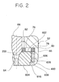
- FIG. 2 is an enlarged portion of the cross-sectional view of the fuel injector assembly shown in FIG. 1, which illustrates the thermally isolated seat of the present invention.
- FIG. 1 illustrates a preferred embodiment of the fuel injector assembly 10, in particular a high-pressure, direct-injection fuel injector assembly 10.
- the fuel injector assembly 10 has a housing, which includes a fuel inlet 12, a fuel outlet 14, and a fuel passageway 16 extending from the fuel inlet to the fuel outlet 14 along a longitudinal axis 18.
- the housing includes anovermolded plastic member 20 cincturing a metallic support member 22.
- a fuel inlet member 24 with an inlet passage 26 is disposed within the overmolded plastic member 20.
- the inlet passage 26 serves as part of the fuel passageway 16 of the fuel injector assembly 10.
- a fuel filter 28 and an adjustable tube 30 are provided in the inlet passage 26.
- the adjustable tube 30 is position-able along the longitudinal axis 18 before being secured in place to vary the length of an armature bias spring 32, which control the quantity of fluid flow within the injector.
- the overmolded plastic member 20 also supports a socket that receives a plug (not shown) to operatively connect the fuel injector assembly 10 to an external source of electrical potential, such as an electronic control unit ECU (not shown).
- An elastomeric O-ring 34 is provided in a groove on an exterior extension of the inlet member. The O-ring 34 is biased by a flat spring 38 tosealingly secure the inlet source with a fuel supply member, such as a fuel rail (not shown).
- the metallic support member 22 encloses a coil assembly 40.
- the coil assembly 40 includes a bobbin 42 that retains a coil 44.
- the ends of the coil assembly 40 are operatively connected to the socket through theovermolded plastic member 20.
- An armature 46 is axially aligned with the inlet member by structure to define a spacer 48 therein, a body shell 50, and a body 52.
- the armature 46 has an armature passage 54 aligned along the longitudinal axis 18 with the inlet passage 26 of the inlet member.
- the spacer 48 engages the body 52, which is partially disposed within the body shell 50.
- An armature guide eyelet 56 is located on an inlet portion of a body 60.
- An axially extending body passage 58 connects the inlet portion of the body 60 with an outlet portion of the body 62.
- the armature passage 54 of the armature 46 is axial aligned with the body passage 58 of the body 52 along the longitudinal axis 18.
- a seat 64 which is preferably a metallic material, is located at the outlet portion of the body 62.
- the body 52 has a neck portion 66, which is, preferably, a cylindrical annulus that surrounds a needle 68.
- the needle 68 is operatively connected to the armature 46, and is, preferably, a substantially cylindrical needle 68.
- the cylindrical needle 68 is centrally located within the cylindrical annulus.
- the cylindrical needle 68 is axially aligned with the longitudinal axis 18 of the fuel injector assembly 10.
- Operative performance of the fuel injector assembly 10 is achieved by magnetically coupling the armature 46 to the inlet member near the inlet portion of the body 60.
- a portion of the inlet member proximate the armature 46 serves as part of the magnetic circuit formed with the armature 46 and coil assembly 40.
- the armature 46 is guided by the armature guide eyelet 56 and is responsive to an electromagnetic force generated by the coil assembly 40 for axially reciprocating the armature 46 along the longitudinal axis 18 of the fuel injector assembly 10.
- the electromagnetic force is generated by current flow from the ECU (not shown) through the coil assembly 40. Movement of the armature 46 also moves the operatively attached needle 68.
- the needle 68 engages the seat 64, which opens and closes the seat passage 70 of the seat 64 to permit or inhibit, respectively, fuel from exiting the fuel outlet 14 of the fuel injector 10.
- the needle 68 includes a curved surface 78, which is preferably a spherical surface, that mates with a conical end 80 of a funnel 82 that serves as the preferred seat passage 70 of the seat 64.
- a swirl generator 76 is located in the body passage 58 proximate the seat 64.
- the swirl generator 76 allows the fuel to form a swirl pattern on the seat 64.
- the fuel is swirled on the conical end 72 of the funnel 74 in order to produce a desired spray pattern.
- the swirl generator 76 preferably, is constructed from a pair of flat disks, a guide disk 78 and a swirl disk 80.
- the swirl generator 76 defines a contact area between the seat and the body 52.
- the guide disk 78 provides a support for the needle 68.
- the needle 68 is guided in a central aperture 82 of the guide disk 78.
- the guide disk 78 has a plurality of fuel passage openings that supply fuel from the body passage 58 to the swirl disk 80.
- the swirl disk 80 directs fuel from the fuel passage openings in the guide disk 78 and meters the flow of fuel tangentially toward the seat passage 70 of the seat 64.
- the guide disk 78 and swirl disks 80 that form the swirl generator 76 are secured to a first surface 84 of the seat 64, preferably, by laser welding.
- fuel flows in fluid communication from the fuel inlet source (not shown) through the inlet passage 26 of the inlet member, the armature passage 54 of the armature 46, the body passage 58 of the body 52, the guide disk 78 and the swirl disk 80 of the swirl generator 76, and the seat passage 70 of the seat 64.
- FIG. 2 is an enlarged cross-sectional view of the fuel injector assembly shown in FIG. 1, which illustrates the thermally isolated seat of the present invention.
- the seat 64 includes a first face 602, a second face 604, and a circumferential surface 606 disposed between the first face 602 and the second face 604.
- the circumferential surface 606 includes a first zone 616 and a second zone 626.
- An annular intermediate zone 636 extends between and connects the first zone 616 to the second zone 626.
- the intermediate zone 636 engages the body 52 to define a first contact area between the body 52 and the seat 64.
- the second zone 626 of the circumferential surface 606 is thermally isolated from the body 52 as will be described below.
- the first zone 616 is isolated against thermal conduction from the body 52 by a gaptherebetween. Otherwise, the first contact area between the body 52 and the seat 64 is increased by the area of engagement between the first zone 616 and the body 52.
- the body 52 includes a retention member 400.
- the retention member is in the form of a crimped section of the neck portion 66 of the body 52 and is disposed at the outlet portion of the body 52.
- the retention member 400 includes a surface that engages the intermediate zone 636 of the seat 64 to define a first contact area between the body 52 and the seat 64.
- the first contact area between the body 52 and the seat 64 substantially allows the conduction of thermal energy between the body 52 and the seat 64.
- a seal 200 is disposed between the second zone 626 of thecircumferential surface 606 of the seat 64 and the body 52.
- the seal 200 acts to thermally isolate the seat 64 from the body 52 of the fuel injector assembly 10.
- the seal 200 may be manufactured from a material that is a substantial thermal insulator. By this arrangement, the seal 200 substantially thermally isolates the second zone 626 of the seat 64 from the body 52.
- the seal 200 comprises polytetrafluoroethylene.
- the first contact area between the body 52 and the seat 64 In order to prevent the conduction of thermal energy from the body 52 to the seat 64, it is desirable to substantially minimize the first contact area between the body 52 and the seat 64. By this arrangement, a substantially larger portion of the seat 64 will be substantially thermally isolated from the body 52 by the seal 200.
- the swirl generator 76 also defines a contact area (second contact area) between the body 52 and the seat 62. Thus, it is desirable to substantially minimize the second contact area between the body 52 and the seat 64.
- the seal 200 substantially thermally isolates the seat 64 from the body 52 by preventing the conduction of heat from the body 52 to the seat 64.
- a method of forming the fuel injector assembly 10 includes the steps of engaging the intermediate zone 636 of the seat 64 with the body 52, and thermally isolating the second zone 626 of the seat 65 from the body 52 by disposing the seal 200 therebetween.
- the seal 200 is formed of a material that is a substantial thermal insulator.
- the seal comprisespolytetrafluoroethylene.
- the intermediate zone 636 of the seat 64 is retained with a retention member 400 having a surface that engages the intermediate zone 636 of the seat 64 to define a first contact area between the body 52 and the seat 64.
- the retention member is in the form of a crimped section of the neck portion 66 of the body 52 and is disposed at the outlet portion of the body 52.
- the first contact area between the body 52 and the seat 64 substantially allows the conduction of thermal energy between the body 52 and the seat 64.
Abstract
Description
- This invention relates to a fuel injector assembly, and more particularly to a high-pressure direct injection fuel injector assembly having a seat that is thermally isolated from a body exposed to extreme temperatures within an engine cylinder.
- Experimental testing has shown that the extreme temperatures within an engine cylinder can effect the operative performance characteristics of the fuel injector assembly. First, the excessive temperatures of the engine cylinder can disproportionately distort the components of the fuel injector assembly within the engine cylinder. For example, the body, which is preferably metal, can be distorted an unequal quantity relative to a needle disposed within the body. Distorting of the components of the fuel injector disproportionally can, for example, alter the dimensional tolerances between the components of the fuel injector, i.e., the body, the needle, and the seat, which is believed, under certain operative conditions, to render the fuel injector inoperative. Second, the excess temperatures of the engine cylinder can cause the fuel injector to overheat and coke unburned fuel on the components of the fuel injector, i.e., the tip components of the fuel injector, such as, the seat at an outlet portion of the body. Coking of the fuel injector tip components can block the outlet of the fuel injector, which is believed to affect the fuel spray patterns of the fuel injector. Thus, distorting andcoking of the fuel injector components utilized in a direct inject application is believed to diminish the performance capability of the fuel injector. A seat that is thermally isolated from a body of a fuel injector assembly, it is believed, will substantially avoid the above-discussed problems. Thus, an arrangement of a fuel injector assembly where the seat is substantially thermally isolated from the body (i.e.- the contact area between the seat and the body is minimized) is desirable.
- The present invention provides a fuel injector having a fuel inlet, a fuel outlet, and a fuel passageway extending from the fuel inlet to the fuel outlet along a longitudinal axis, the fuel injector including a body, an armature adjacent the inlet portion of the body having an inlet portion, an outlet portion, and a neck portion disposed between the inlet portion and the outlet portion, a needle operatively connected to the armature, a seat proximate the needle, and a seal. The seat has a first face, a second face, and acircumferential surface disposed between the first face and the second face, the circumferential surface including a first zone and a second zone that are connected by an intermediate zone, the intermediate zone engaging the body. The seal is disposed between the second zone of the seat and the body that thermally isolates the second zone of the seat from the body.
- The present invention also provides a body and a seat for a fuel injector having a fuel inlet, a fuel outlet, and a fuel passageway extending from the fuel inlet to the fuel outlet along a longitudinal axis. The body includes an inlet portion, an outlet portion, and a neck portion disposed between the inlet portion and the outlet portion. The seat includes a first face, a second face, and ancircumferential surface disposed between the first face and the second face, thecircumferential surface including a first zone and a second zone that are connected by an intermediate zone, the intermediate zone engaging the body and the second zone being thermally isolated from the body.
- The present invention also provides a method of forming a fuel injector having a fuel inlet, a fuel outlet,a fuel passageway extending from the fuel inlet to the fuel outlet along a longitudinal axis, a body, and a seat. The body has an inlet portion, an outlet portion, and a neck portion disposed between the inlet portion and the outlet portion. The seat has a first face, a second face, and acircumferential surface disposed between the first face and the second face, thecircumferential surface including a first zone and a second zone that are connected by an intermediate zone. The method includes the steps of engaging the intermediate zone of the seat with the body, and thermally isolating the second zone of the seat from the body.
- The accompanying drawings, which are incorporated herein and constitute part of this specification, illustrate presently preferred embodiments of the invention, and, together with the general description given above and the detailed description given below, serve to explain features of the invention.
- FIG. 1 is a cross-sectional view of a fuel injector assembly of the present invention taken along its longitudinal axis;
- FIG. 2 is an enlarged portion of the cross-sectional view of the fuel injector assembly shown in FIG. 1, which illustrates the thermally isolated seat of the present invention.
- FIG. 1 illustrates a preferred embodiment of the
fuel injector assembly 10, in particular a high-pressure, direct-injectionfuel injector assembly 10. Thefuel injector assembly 10 has a housing, which includes afuel inlet 12, afuel outlet 14, and afuel passageway 16 extending from the fuel inlet to thefuel outlet 14 along alongitudinal axis 18. The housing includes anovermolded plastic member 20 cincturing ametallic support member 22. - A
fuel inlet member 24 with aninlet passage 26 is disposed within the overmolded plastic member 20. Theinlet passage 26 serves as part of thefuel passageway 16 of thefuel injector assembly 10. Afuel filter 28 and anadjustable tube 30 are provided in theinlet passage 26. Theadjustable tube 30 is position-able along thelongitudinal axis 18 before being secured in place to vary the length of anarmature bias spring 32, which control the quantity of fluid flow within the injector. The overmolded plastic member 20 also supports a socket that receives a plug (not shown) to operatively connect thefuel injector assembly 10 to an external source of electrical potential, such as an electronic control unit ECU (not shown). An elastomeric O-ring 34 is provided in a groove on an exterior extension of the inlet member. The O-ring 34 is biased by aflat spring 38 tosealingly secure the inlet source with a fuel supply member, such as a fuel rail (not shown). - The
metallic support member 22 encloses acoil assembly 40. Thecoil assembly 40 includes abobbin 42 that retains acoil 44. The ends of thecoil assembly 40 are operatively connected to the socket through theovermolded plastic member 20. Anarmature 46 is axially aligned with the inlet member by structure to define aspacer 48 therein, abody shell 50, and abody 52. Thearmature 46 has anarmature passage 54 aligned along thelongitudinal axis 18 with theinlet passage 26 of the inlet member. - The
spacer 48 engages thebody 52, which is partially disposed within thebody shell 50. Anarmature guide eyelet 56 is located on an inlet portion of abody 60. An axially extendingbody passage 58 connects the inlet portion of thebody 60 with an outlet portion of thebody 62. Thearmature passage 54 of thearmature 46 is axial aligned with thebody passage 58 of thebody 52 along thelongitudinal axis 18. Aseat 64, which is preferably a metallic material, is located at the outlet portion of thebody 62. - The
body 52 has aneck portion 66, which is, preferably, a cylindrical annulus that surrounds aneedle 68. Theneedle 68 is operatively connected to thearmature 46, and is, preferably, a substantiallycylindrical needle 68. Thecylindrical needle 68 is centrally located within the cylindrical annulus. Thecylindrical needle 68 is axially aligned with thelongitudinal axis 18 of thefuel injector assembly 10. - Operative performance of the
fuel injector assembly 10 is achieved by magnetically coupling thearmature 46 to the inlet member near the inlet portion of thebody 60. A portion of the inlet member proximate thearmature 46 serves as part of the magnetic circuit formed with thearmature 46 andcoil assembly 40. Thearmature 46 is guided by thearmature guide eyelet 56 and is responsive to an electromagnetic force generated by thecoil assembly 40 for axially reciprocating thearmature 46 along thelongitudinal axis 18 of thefuel injector assembly 10. The electromagnetic force is generated by current flow from the ECU (not shown) through thecoil assembly 40. Movement of thearmature 46 also moves the operatively attachedneedle 68. Theneedle 68 engages theseat 64, which opens and closes theseat passage 70 of theseat 64 to permit or inhibit, respectively, fuel from exiting thefuel outlet 14 of thefuel injector 10. Theneedle 68 includes acurved surface 78, which is preferably a spherical surface, that mates with aconical end 80 of afunnel 82 that serves as thepreferred seat passage 70 of theseat 64. - A
swirl generator 76 is located in thebody passage 58 proximate theseat 64. Theswirl generator 76 allows the fuel to form a swirl pattern on theseat 64. In particular, for example, the fuel is swirled on the conical end 72 of the funnel 74 in order to produce a desired spray pattern. Theswirl generator 76, preferably, is constructed from a pair of flat disks, aguide disk 78 and aswirl disk 80. Theswirl generator 76 defines a contact area between the seat and thebody 52. Theguide disk 78 provides a support for theneedle 68. - The
needle 68 is guided in acentral aperture 82 of theguide disk 78. Theguide disk 78 has a plurality of fuel passage openings that supply fuel from thebody passage 58 to theswirl disk 80. Theswirl disk 80 directs fuel from the fuel passage openings in theguide disk 78 and meters the flow of fuel tangentially toward theseat passage 70 of theseat 64. Theguide disk 78 andswirl disks 80 that form theswirl generator 76 are secured to a first surface 84 of theseat 64, preferably, by laser welding. During operation, fuel flows in fluid communication from the fuel inlet source (not shown) through theinlet passage 26 of the inlet member, thearmature passage 54 of thearmature 46, thebody passage 58 of thebody 52, theguide disk 78 and theswirl disk 80 of theswirl generator 76, and theseat passage 70 of theseat 64. - FIG. 2 is an enlarged cross-sectional view of the fuel injector assembly shown in FIG. 1, which illustrates the thermally isolated seat of the present invention. The
seat 64 includes afirst face 602, asecond face 604, and acircumferential surface 606 disposed between thefirst face 602 and thesecond face 604. Thecircumferential surface 606 includes afirst zone 616 and asecond zone 626. An annularintermediate zone 636 extends between and connects thefirst zone 616 to thesecond zone 626. Theintermediate zone 636 engages thebody 52 to define a first contact area between thebody 52 and theseat 64. Thesecond zone 626 of thecircumferential surface 606 is thermally isolated from thebody 52 as will be described below. Preferably, thefirst zone 616 is isolated against thermal conduction from thebody 52 by a gaptherebetween. Otherwise, the first contact area between thebody 52 and theseat 64 is increased by the area of engagement between thefirst zone 616 and thebody 52. - The
body 52 includes aretention member 400. Preferably, the retention member is in the form of a crimped section of theneck portion 66 of thebody 52 and is disposed at the outlet portion of thebody 52. Theretention member 400 includes a surface that engages theintermediate zone 636 of theseat 64 to define a first contact area between thebody 52 and theseat 64. The first contact area between thebody 52 and theseat 64 substantially allows the conduction of thermal energy between thebody 52 and theseat 64. - A
seal 200 is disposed between thesecond zone 626 ofthecircumferential surface 606 of theseat 64 and thebody 52. Theseal 200 acts to thermally isolate theseat 64 from thebody 52 of thefuel injector assembly 10. Theseal 200 may be manufactured from a material that is a substantial thermal insulator. By this arrangement, theseal 200 substantially thermally isolates thesecond zone 626 of theseat 64 from thebody 52. Preferably, theseal 200 comprises polytetrafluoroethylene. - In order to prevent the conduction of thermal energy from the
body 52 to theseat 64, it is desirable to substantially minimize the first contact area between thebody 52 and theseat 64. By this arrangement, a substantially larger portion of theseat 64 will be substantially thermally isolated from thebody 52 by theseal 200. Theswirl generator 76 also defines a contact area (second contact area) between thebody 52 and theseat 62. Thus, it is desirable to substantially minimize the second contact area between thebody 52 and theseat 64. Theseal 200 substantially thermally isolates theseat 64 from thebody 52 by preventing the conduction of heat from thebody 52 to theseat 64. - A method of forming the
fuel injector assembly 10 includes the steps of engaging theintermediate zone 636 of theseat 64 with thebody 52, and thermally isolating thesecond zone 626 of the seat 65 from thebody 52 by disposing theseal 200 therebetween. Theseal 200 is formed of a material that is a substantial thermal insulator. Preferably, the seal comprisespolytetrafluoroethylene. Theintermediate zone 636 of theseat 64 is retained with aretention member 400 having a surface that engages theintermediate zone 636 of theseat 64 to define a first contact area between thebody 52 and theseat 64. Preferably, the retention member is in the form of a crimped section of theneck portion 66 of thebody 52 and is disposed at the outlet portion of thebody 52. The first contact area between thebody 52 and theseat 64 substantially allows the conduction of thermal energy between thebody 52 and theseat 64. - While the present invention has been disclosed with reference to certain preferred embodiments, numerous modifications, alterations, and changes to the described embodiments are possible without departing from the sphere and scope of the present invention, as defined in the appended claims. Accordingly, it is intended that the present invention not be limited to the described embodiments, but that it have the full scope defined by the language of the following claims, and equivalents thereof.
Claims (17)
- A fuel injector having a fuel inlet, a fuel outlet, and a fuel passageway extending from the fuel inlet to the fuel outlet along a longitudinal axis, the fuel injector comprising:a body having an inlet portion, an outlet portion, and a neck portion disposed between the inlet portion and the outlet portion;an armature adjacent the inlet portion of the body;a needle operatively connected to the armature;a seat proximate the needle having a first face, a second face, and a circumferential surface disposed between the first face and the second face, the circumferential surface including a first zone and a second zone that are connected by an intermediate zone, the intermediate zone engaging the body; anda seal disposed between the second zone of the seat and the body that thermally isolates the second zone of the seat from the body.
- The fuel injector according to claim 1, wherein the body includes a retention member that engages the intermediate zone of the seat.
- The fuel injector according to claim 2, wherein the retention member includes a surface that engages the intermediate zone of the seat to define a first contact area between the body and the seat.
- The fuel injector according to claim 3, wherein the retention member comprises a crimped section on the neck portion and is disposed at the outlet portion of the body.
- The fuel injector according the claim 1, further comprising:a swirl generator disk comprising a first surface and a second surface, the first surface of the swirl generator disk adjacent the armature, the second surface of the swirl generator disk adjacent the first face of the seat; anda guide disk comprising a first surface and a second surface, the first surface of the guide disk adjacent the armature, the second surface of the guide disk adjacent the first face of the swirl generator disk.
- The fuel injector according to claim 5, wherein the swirl generator disk and the guide disk define a second contact area between the body and the seat.
- The fuel injector according to claim 1, wherein the seal comprises polytetrafluoroethylene.
- A body and a seat for a fuel injector having a fuel inlet, a fuel outlet, and a fuel passageway extending from the fuel inlet to the fuel outlet along a longitudinal axis, the body and the seat comprising:a body having an inlet portion, an outlet portion, and a neck portion disposed between the inlet portion and the outlet portion; anda seat having a first face, a second face, and an circumferential surface disposed between the first face and the second face, thecircumferential surface including a first zone and a second zone that are connected by an intermediate zone, the intermediate zone engaging the body and the second zone being thermally isolated from the body.
- The body and the seat according to claim 8, wherein the body includes a retention member having a surface engaging the intermediate zone of the seat, the surface of the retention member defining a first contact area between the body and the seat.
- The body and the seat according to claim 9, further comprising:a swirl generator disk comprising a first surface and a second surface, the first surface of the swirl generator disk adjacent the inlet portion of the body, the second surface of the swirl generator disk adjacent the first face of the seat; anda guide disk comprising a first surface and a second surface, the first surface of the guide disk adjacent the inlet portion of the body, the second surface of the guide disk adjacent the first face of the swirl generator disk.
- The body and seat according to claim 8, further comprising:
a seal disposed between the second zone of the seat and the body, the seal thermally isolating the seat from the body. - A method of forming a fuel injector having a fuel inlet, a fuel outlet, a fuel passageway extending from the fuel inlet to the fuel outlet along a longitudinal axis, a body having an inlet portion, an outlet portion, and a neck portion disposed between the inlet portion and the outlet portion, and a seat having a first face, a second face, and a circumferential surface disposed between the first face and the second face, the circumferential surface including a first zone and a second zone that are connected by an intermediate zone, the method comprising:engaging the intermediate zone of the seat with the body; andthermally isolating the second zone of the seat from the body.
- The method according to claim 12, further comprising:
disposing a seal between the second zone of the seat and the body to thermally isolate the seat from the body. - The method according to claim 12, further comprising:
retaining the intermediate zone of the seat and the body with a retention member. - The method according to claim 14, wherein the retention member comprises a surface that engages the intermediate zone of the seat to define a first contact area between the body and the seat.
- The method according to claim 15, wherein the retention member includes a crimped section on the neck portion and is disposed at the outlet portion of the body.
- The method according to claim 12, wherein the seal comprises polytetrafluoroethylene.
Applications Claiming Priority (2)
| Application Number | Priority Date | Filing Date | Title |
|---|---|---|---|
| US09/474,766 US6848634B1 (en) | 1999-12-30 | 1999-12-30 | Fuel injector with thermally isolated seat |
| US474766 | 1999-12-30 |
Publications (3)
| Publication Number | Publication Date |
|---|---|
| EP1113166A2 true EP1113166A2 (en) | 2001-07-04 |
| EP1113166A3 EP1113166A3 (en) | 2003-12-17 |
| EP1113166B1 EP1113166B1 (en) | 2006-02-22 |
Family
ID=23884846
Family Applications (1)
| Application Number | Title | Priority Date | Filing Date |
|---|---|---|---|
| EP00204643A Expired - Lifetime EP1113166B1 (en) | 1999-12-30 | 2000-12-20 | Fuel injector with thermally isolated seat |
Country Status (3)
| Country | Link |
|---|---|
| US (1) | US6848634B1 (en) |
| EP (1) | EP1113166B1 (en) |
| DE (1) | DE60026110T2 (en) |
Cited By (1)
| Publication number | Priority date | Publication date | Assignee | Title |
|---|---|---|---|---|
| EP1217204A1 (en) * | 2000-12-22 | 2002-06-26 | Caterpillar Inc. | Partially plastic fuel injector component and method of making the same |
Families Citing this family (1)
| Publication number | Priority date | Publication date | Assignee | Title |
|---|---|---|---|---|
| US9381452B2 (en) | 2010-06-18 | 2016-07-05 | Hamilton Sundstrand Corporation | Coke tolerant fuel filter |
Citations (4)
| Publication number | Priority date | Publication date | Assignee | Title |
|---|---|---|---|---|
| FR1089892A (en) * | 1952-12-30 | 1955-03-22 | Friedmann & Maier Ag | Injection nozzle for internal combustion engines |
| GB759524A (en) * | 1952-12-30 | 1956-10-17 | Emmerich Satzger | An improved fuel injection nozzle for fuel injection internal combustion engines |
| FR1157264A (en) * | 1955-08-31 | 1958-05-28 | Nozzle-injector for combustion engines | |
| GB834826A (en) * | 1955-08-31 | 1960-05-11 | Karl Uccusic | Fuel injection nozzle for internal-combustion engines |
Family Cites Families (13)
| Publication number | Priority date | Publication date | Assignee | Title |
|---|---|---|---|---|
| US1664616A (en) * | 1926-05-26 | 1928-04-03 | Louis O French | Fuel-control valve |
| JPS58195058A (en) * | 1982-05-07 | 1983-11-14 | Toyota Motor Corp | Air assist device for fuel injection internal-combustion engine |
| DE3418762A1 (en) * | 1984-05-19 | 1985-11-21 | Robert Bosch Gmbh, 7000 Stuttgart | INJECTION VALVE |
| US4569484A (en) * | 1984-08-31 | 1986-02-11 | The United States Of America As Represented By The United States Department Of Energy | Air blast type coal slurry fuel injector |
| US5098064A (en) * | 1990-02-16 | 1992-03-24 | Siemens Automotive L.P. | Engine throttle blade sealing |
| JP2521825Y2 (en) * | 1991-02-28 | 1997-01-08 | 愛三工業株式会社 | Fuel injection device |
| US5170945A (en) * | 1991-12-10 | 1992-12-15 | Siemens Automotive L.P. | Fuel injector that swirls and throttles the flow to create to a toroidal fuel cloud |
| US5330100A (en) * | 1992-01-27 | 1994-07-19 | Igor Malinowski | Ultrasonic fuel injector |
| DE19611283C1 (en) * | 1996-03-22 | 1997-10-23 | Florian Virchow | Spark plug connector for an internal combustion engine |
| US5875972A (en) * | 1997-02-06 | 1999-03-02 | Siemens Automotive Corporation | Swirl generator in a fuel injector |
| DE19736682A1 (en) * | 1997-08-22 | 1999-02-25 | Bosch Gmbh Robert | Fuel injector for internal combustion engine |
| DE19829380A1 (en) * | 1998-07-01 | 2000-01-05 | Bosch Gmbh Robert | Fuel injection valve for IC engines |
| US6065692A (en) * | 1999-06-09 | 2000-05-23 | Siemens Automotive Corporation | Valve seat subassembly for fuel injector |
-
1999
- 1999-12-30 US US09/474,766 patent/US6848634B1/en not_active Expired - Fee Related
-
2000
- 2000-12-20 EP EP00204643A patent/EP1113166B1/en not_active Expired - Lifetime
- 2000-12-20 DE DE60026110T patent/DE60026110T2/en not_active Expired - Lifetime
Patent Citations (4)
| Publication number | Priority date | Publication date | Assignee | Title |
|---|---|---|---|---|
| FR1089892A (en) * | 1952-12-30 | 1955-03-22 | Friedmann & Maier Ag | Injection nozzle for internal combustion engines |
| GB759524A (en) * | 1952-12-30 | 1956-10-17 | Emmerich Satzger | An improved fuel injection nozzle for fuel injection internal combustion engines |
| FR1157264A (en) * | 1955-08-31 | 1958-05-28 | Nozzle-injector for combustion engines | |
| GB834826A (en) * | 1955-08-31 | 1960-05-11 | Karl Uccusic | Fuel injection nozzle for internal-combustion engines |
Cited By (2)
| Publication number | Priority date | Publication date | Assignee | Title |
|---|---|---|---|---|
| EP1217204A1 (en) * | 2000-12-22 | 2002-06-26 | Caterpillar Inc. | Partially plastic fuel injector component and method of making the same |
| US6631857B2 (en) | 2000-12-22 | 2003-10-14 | Caterpillar Inc | Partially plastic fuel injector component and method of making the same |
Also Published As
| Publication number | Publication date |
|---|---|
| EP1113166A3 (en) | 2003-12-17 |
| DE60026110T2 (en) | 2006-08-03 |
| DE60026110D1 (en) | 2006-04-27 |
| US6848634B1 (en) | 2005-02-01 |
| EP1113166B1 (en) | 2006-02-22 |
Similar Documents
| Publication | Publication Date | Title |
|---|---|---|
| US6257496B1 (en) | Fuel injector having an integrated seat and swirl generator | |
| US5884850A (en) | Fuel injection valve | |
| US6341412B1 (en) | Methods of forming a sheath and plastic ring on a electromagnetically operated valve | |
| US4678124A (en) | Electromagnetically actuatable valve in particular a fuel injection valve | |
| CN105829701B (en) | Fuel injection valve | |
| US6142395A (en) | Fuel injection valve and method for manufacturing a fuel injection valve | |
| US4634055A (en) | Injection valve with upstream internal metering | |
| US5829688A (en) | Injection valve for directly injecting fuel into an internal combustion engine | |
| KR100853642B1 (en) | Fuel-injection valve | |
| JP2004518066A (en) | Fuel injection valve | |
| US6921035B2 (en) | Fuel injection valve | |
| JP2005504923A (en) | Fuel injection valve | |
| KR20030007944A (en) | Fuel injection valve | |
| US9038604B2 (en) | Electromagnetically actuable valve | |
| JPH02256980A (en) | Solenoid valve | |
| JP2004518874A (en) | Fuel injection valve | |
| US7458530B2 (en) | Fuel injector sleeve armature | |
| US5957390A (en) | Electromagnetically actuable fuel injection valve | |
| US6886758B1 (en) | Fuel injector temperature stabilizing arrangement and method | |
| EP1113166B1 (en) | Fuel injector with thermally isolated seat | |
| US6676045B2 (en) | Fuel injection valve comprising an adjusting bush | |
| US6202936B1 (en) | Fuel injector having a flat disk swirl generator | |
| US6983900B2 (en) | Fuel injector | |
| US6334576B1 (en) | Fuel injector having a ball seat with multiple tip geometry | |
| US6676046B2 (en) | Closure member with armature strap |
Legal Events
| Date | Code | Title | Description |
|---|---|---|---|
| PUAI | Public reference made under article 153(3) epc to a published international application that has entered the european phase |
Free format text: ORIGINAL CODE: 0009012 |
|
| AK | Designated contracting states |
Kind code of ref document: A2 Designated state(s): AT BE CH CY DE DK ES FI FR GB GR IE IT LI LU MC NL PT SE TR |
|
| AX | Request for extension of the european patent |
Free format text: AL;LT;LV;MK;RO;SI |
|
| PUAL | Search report despatched |
Free format text: ORIGINAL CODE: 0009013 |
|
| AK | Designated contracting states |
Kind code of ref document: A3 Designated state(s): AT BE CH CY DE DK ES FI FR GB GR IE IT LI LU MC NL PT SE TR |
|
| AX | Request for extension of the european patent |
Extension state: AL LT LV MK RO SI |
|
| RIC1 | Information provided on ipc code assigned before grant |
Ipc: 7F 02M 61/12 B Ipc: 7F 02M 51/06 B Ipc: 7F 02M 61/20 B Ipc: 7F 02M 61/16 B Ipc: 7F 02M 53/04 A |
|
| AKX | Designation fees paid |
Designated state(s): DE FR GB IT |
|
| 17P | Request for examination filed |
Effective date: 20040805 |
|
| 17Q | First examination report despatched |
Effective date: 20041103 |
|
| GRAP | Despatch of communication of intention to grant a patent |
Free format text: ORIGINAL CODE: EPIDOSNIGR1 |
|
| GRAS | Grant fee paid |
Free format text: ORIGINAL CODE: EPIDOSNIGR3 |
|
| RAP1 | Party data changed (applicant data changed or rights of an application transferred) |
Owner name: SIEMENS VDO AUTOMOTIVE CORPORATION |
|
| GRAA | (expected) grant |
Free format text: ORIGINAL CODE: 0009210 |
|
| AK | Designated contracting states |
Kind code of ref document: B1 Designated state(s): DE FR GB IT |
|
| REG | Reference to a national code |
Ref country code: GB Ref legal event code: FG4D |
|
| REF | Corresponds to: |
Ref document number: 60026110 Country of ref document: DE Date of ref document: 20060427 Kind code of ref document: P |
|
| ET | Fr: translation filed | ||
| PLBE | No opposition filed within time limit |
Free format text: ORIGINAL CODE: 0009261 |
|
| STAA | Information on the status of an ep patent application or granted ep patent |
Free format text: STATUS: NO OPPOSITION FILED WITHIN TIME LIMIT |
|
| 26N | No opposition filed |
Effective date: 20061123 |
|
| PGFP | Annual fee paid to national office [announced via postgrant information from national office to epo] |
Ref country code: GB Payment date: 20121220 Year of fee payment: 13 |
|
| PGFP | Annual fee paid to national office [announced via postgrant information from national office to epo] |
Ref country code: FR Payment date: 20130130 Year of fee payment: 13 |
|
| GBPC | Gb: european patent ceased through non-payment of renewal fee |
Effective date: 20131220 |
|
| REG | Reference to a national code |
Ref country code: FR Ref legal event code: ST Effective date: 20140829 |
|
| PG25 | Lapsed in a contracting state [announced via postgrant information from national office to epo] |
Ref country code: GB Free format text: LAPSE BECAUSE OF NON-PAYMENT OF DUE FEES Effective date: 20131220 Ref country code: FR Free format text: LAPSE BECAUSE OF NON-PAYMENT OF DUE FEES Effective date: 20131231 |
|
| PGFP | Annual fee paid to national office [announced via postgrant information from national office to epo] |
Ref country code: DE Payment date: 20141231 Year of fee payment: 15 |
|
| PGFP | Annual fee paid to national office [announced via postgrant information from national office to epo] |
Ref country code: IT Payment date: 20141223 Year of fee payment: 15 |
|
| REG | Reference to a national code |
Ref country code: DE Ref legal event code: R119 Ref document number: 60026110 Country of ref document: DE |
|
| PG25 | Lapsed in a contracting state [announced via postgrant information from national office to epo] |
Ref country code: DE Free format text: LAPSE BECAUSE OF NON-PAYMENT OF DUE FEES Effective date: 20160701 |
|
| PG25 | Lapsed in a contracting state [announced via postgrant information from national office to epo] |
Ref country code: IT Free format text: LAPSE BECAUSE OF NON-PAYMENT OF DUE FEES Effective date: 20151220 |