EP1113146B1 - Turbomachine with a seal assembly - Google Patents
Turbomachine with a seal assembly Download PDFInfo
- Publication number
- EP1113146B1 EP1113146B1 EP00311632A EP00311632A EP1113146B1 EP 1113146 B1 EP1113146 B1 EP 1113146B1 EP 00311632 A EP00311632 A EP 00311632A EP 00311632 A EP00311632 A EP 00311632A EP 1113146 B1 EP1113146 B1 EP 1113146B1
- Authority
- EP
- European Patent Office
- Prior art keywords
- rotor
- main body
- blades
- casing
- flexible body
- Prior art date
- Legal status (The legal status is an assumption and is not a legal conclusion. Google has not performed a legal analysis and makes no representation as to the accuracy of the status listed.)
- Expired - Lifetime
Links
Images

Classifications
-
- F—MECHANICAL ENGINEERING; LIGHTING; HEATING; WEAPONS; BLASTING
- F01—MACHINES OR ENGINES IN GENERAL; ENGINE PLANTS IN GENERAL; STEAM ENGINES
- F01D—NON-POSITIVE DISPLACEMENT MACHINES OR ENGINES, e.g. STEAM TURBINES
- F01D11/00—Preventing or minimising internal leakage of working-fluid, e.g. between stages
- F01D11/08—Preventing or minimising internal leakage of working-fluid, e.g. between stages for sealing space between rotor blade tips and stator
- F01D11/12—Preventing or minimising internal leakage of working-fluid, e.g. between stages for sealing space between rotor blade tips and stator using a rubstrip, e.g. erodible. deformable or resiliently-biased part
- F01D11/122—Preventing or minimising internal leakage of working-fluid, e.g. between stages for sealing space between rotor blade tips and stator using a rubstrip, e.g. erodible. deformable or resiliently-biased part with erodable or abradable material
-
- F—MECHANICAL ENGINEERING; LIGHTING; HEATING; WEAPONS; BLASTING
- F05—INDEXING SCHEMES RELATING TO ENGINES OR PUMPS IN VARIOUS SUBCLASSES OF CLASSES F01-F04
- F05D—INDEXING SCHEME FOR ASPECTS RELATING TO NON-POSITIVE-DISPLACEMENT MACHINES OR ENGINES, GAS-TURBINES OR JET-PROPULSION PLANTS
- F05D2300/00—Materials; Properties thereof
- F05D2300/10—Metals, alloys or intermetallic compounds
-
- F—MECHANICAL ENGINEERING; LIGHTING; HEATING; WEAPONS; BLASTING
- F05—INDEXING SCHEMES RELATING TO ENGINES OR PUMPS IN VARIOUS SUBCLASSES OF CLASSES F01-F04
- F05D—INDEXING SCHEME FOR ASPECTS RELATING TO NON-POSITIVE-DISPLACEMENT MACHINES OR ENGINES, GAS-TURBINES OR JET-PROPULSION PLANTS
- F05D2300/00—Materials; Properties thereof
- F05D2300/20—Oxide or non-oxide ceramics
- F05D2300/21—Oxide ceramics
-
- F—MECHANICAL ENGINEERING; LIGHTING; HEATING; WEAPONS; BLASTING
- F05—INDEXING SCHEMES RELATING TO ENGINES OR PUMPS IN VARIOUS SUBCLASSES OF CLASSES F01-F04
- F05D—INDEXING SCHEME FOR ASPECTS RELATING TO NON-POSITIVE-DISPLACEMENT MACHINES OR ENGINES, GAS-TURBINES OR JET-PROPULSION PLANTS
- F05D2300/00—Materials; Properties thereof
- F05D2300/50—Intrinsic material properties or characteristics
- F05D2300/501—Elasticity
-
- F—MECHANICAL ENGINEERING; LIGHTING; HEATING; WEAPONS; BLASTING
- F05—INDEXING SCHEMES RELATING TO ENGINES OR PUMPS IN VARIOUS SUBCLASSES OF CLASSES F01-F04
- F05D—INDEXING SCHEME FOR ASPECTS RELATING TO NON-POSITIVE-DISPLACEMENT MACHINES OR ENGINES, GAS-TURBINES OR JET-PROPULSION PLANTS
- F05D2300/00—Materials; Properties thereof
- F05D2300/60—Properties or characteristics given to material by treatment or manufacturing
- F05D2300/601—Fabrics
- F05D2300/6012—Woven fabrics
-
- Y—GENERAL TAGGING OF NEW TECHNOLOGICAL DEVELOPMENTS; GENERAL TAGGING OF CROSS-SECTIONAL TECHNOLOGIES SPANNING OVER SEVERAL SECTIONS OF THE IPC; TECHNICAL SUBJECTS COVERED BY FORMER USPC CROSS-REFERENCE ART COLLECTIONS [XRACs] AND DIGESTS
- Y02—TECHNOLOGIES OR APPLICATIONS FOR MITIGATION OR ADAPTATION AGAINST CLIMATE CHANGE
- Y02T—CLIMATE CHANGE MITIGATION TECHNOLOGIES RELATED TO TRANSPORTATION
- Y02T50/00—Aeronautics or air transport
- Y02T50/60—Efficient propulsion technologies, e.g. for aircraft
Definitions
- the present invention generally relates to rotary machines, such as steam and gas turbines, and, more particularly, is concerned with a rotary machine having a seal assembly for controlling clearance between tips of rotating rotor blades and a stationary outer casing of the rotary machine.
- a steam turbine has a steam path which typically includes, in serial-flow relationship, a steam inlet, a turbine, and a steam outlet.
- a gas turbine has a gas path which typically includes, in serial-flow relationship, an air intake (or inlet), a compressor, a combustor, a turbine, and a gas outlet (or exhaust nozzle).
- Compressor and turbine sections include at least one circumferential row of rotating blades. The free ends or tips of the rotating blades are surrounded by a stator casing.
- the efficiency of the turbine depends in part on the radial clearance or gap between the rotor blade tips and the surrounding casing. If the clearance is too large, more of the steam or gas flow will leak through the gap between the rotor blade tips and the surrounding casing, decreasing the turbine's efficiency. If the clearance is too small, the rotor blade tips may strike the surrounding casing during certain turbine operating conditions.
- US-4 135 851 a shroud wearable or abradable by the abrasion of the rotor blades of a turbine engine or compressor shrouds the rotor blades.
- US-A-5 456 576 discloses a gas turbine engine including a plurality of rotor blades enclosed in an engine case. A variable position engine case liner is disposed radially inward of the engine case and radially outward of the rotor blade tips. Biasing mechanism, disposed between the liner and the engine case, urge the liner radially inward from the engine case.
- GB-A-1 528 421 discloses a turbine or compressor in which an abradable seal is provided on a shroud member adjacent the tips of the rotor or impeller blades.
- the abradable seal comprises a layer of a baked mixture of a ceramic fibre and an inorganic binder attached to the inner surface of the shroud member.
- US-A-4 530 884 discloses a ceramic-metal composite laminate capable of exposure to high temperature differentials without damage, consisting of an inner ceramic layer, an outer metal layer and an intermediate interface layer of a low modulus metallic low density structure having a high melting point.
- EP-A-0 376 071 a braided filamentary sealing element is provided for use between components in a gas turbine engine or other machine where a clearance space is provided between the components.
- Clearance control devices such as rigid abradable shrouds, have been proposed in the past to accommodate rotor-to-casing clearance change. However, none are believed to represent an optimum design for controlling such clearance. Consequently, a need still remains for an innovation which will provide a solution to the above-described clearance control problem without introducing any new problems in place thereof.
- the present invention provides a rotary machine with a flexible abradable seal assembly designed to satisfy the aforementioned need.
- the flexible abradable seal assembly controls the radial clearance between the rotating rotor blades and the stationary outer casing of the rotary machine by flexing and abrading in response to contact therewith by the blade tips due to differential growth of the rotor and blades relative to the casing and thereby reduces contact severity by moving abradable layer with blade.
- the flexibility of the seal assembly of the present invention will result in less heat generation and material removal.
- the reduced wear rates of the seal assembly will provide tighter blade tip clearances for longer periods yielding better operating efficiency.
- a rotary machine which includes a rotor rotatable about a longitudinal axis and having an outer surface, a plurality of blades mounted on and spaced from one another circumferentially about and extending radially outward relative to the longitudinal axis and from the outer surface of the rotor to end tips of the blades, an outer casing having an annular shape and an inner circumferential surface and being stationarily disposed about and spaced radially outwardly from the rotor and the blades so as to define an annular gap between the inner circumferential surface of the outer casing and the end tips of the blades, and a flexible abradable seal assembly attached on the inner circumferential surface of the outer casing and disposed within the annular clearance gap between the casing and blade tips such that, during periods of differential growth of the rotor and blades relative to the casing, the seal assembly flexes and abrades in response to contact therewith by the tips of the blades moving with the rotor and
- the seal assembly includes an elongated flexible body having an arcuate shape generally conforming to the annular shape of the inner circumferential surface of the outer casing, a pair of opposite spaced apart longitudinally extending edge portions spaced respectively upstream and downstream of the end tips of the rotor blades, and a main body portion extending between and interconnecting the opposite edge portions and being disposed outwardly of and aligned with the end tips of the rotor blades.
- the elongated flexible body has a portion disposed adjacent to the end tips of the rotor blades that is a material abradable in response to contact therewith by the end tips of the rotor blades.
- the flexible body itself is made of said abradable material.
- the seal assembly further includes means for securing the flexible body at the opposite edge portions thereof to the inner circumferential surface of the outer casing.
- the main body portion of said flexible body has a central section overlying said end tips of said rotor blades and means for interconnecting said opposite edge portions of said flexible body and said central section of said main body portion such that said central section of said main body portion is spaced sufficiently inwardly from said inner circumferential surface of said outer casing to allow flexing of said main body portion toward said outer casing in response to contact by said end tips of said rotor blades.
- the flexible body is made up of an annular array of a plurality of like arcuate-shaped body segments disposed end-to-end with one another.
- the securing means can be welds or fasteners.
- Rotary machines include, without limitation, centrifugal compressors, generators, and turbines.
- Turbines include, without limitation, steam turbines and gas turbines. Turbines have, without limitation, compressor sections and turbine sections.
- Figure 1 shows only a portion of a rotary machine, such portion including, among other elements, a housing and a rotor of a turbine.
- FIG. 1 there is illustrated in a diagrammatical form a turbine, generally designated 10, of the present invention having a rotor 12 rotatable about a central longitudinal axis A and having an outer annular surface 12a, a plurality of blades 14 fixedly mounted on, spaced from one another circumferentially about, and extending radially outward from the outer annular surface 12a of the rotor 12 to end tips 14a of the blades 14, and an outer casing 16 having a generally annular and cylindrical shape and an inner circumferential surface 16a and' being stationarily disposed about and spaced radially outwardly from the rotor 12 and blades 14 so as to define an annular gap 18 between the inner circumferential surface 16a of the outer casing and the end tips 14a of the rotor blades 14.
- a flexible abradable seal assembly 20 is attached on the inner circumference 16a of the outer casing 16 and disposed within the annular gap 18 defined between the inner circumference 16a of the casing 16 and the end tips 14a of the blades 14 rotating with the rotor 12.
- the seal assembly 18 flexes and abrades in response to contact therewith by the moving blade tips 14a. In such manner, contact by the moving blade tips 14a with the stationary casing 16 is avoided and the clearance between the stationary casing 16 and the moving rotor blades 14 is thereby controlled by the seal assembly 18 of the present invention.
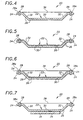
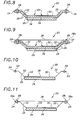
- the flexible abradable seal assembly 20 can be provided in different modified forms or embodiments as shown in FIGS. 2 to 11 .
- the seal assembly 20 basically includes an elongated flexible body 22 having an arcuate shape generally conforming to the annular shape of the inner circumferential surface 16a of the outer casing 16.
- the flexible body 22 also has a pair of opposite spaced apart longitudinally extending edge portions 24 spaced respectively upstream and downstream of the end tips 14a of the rotor blades 14 and a main body portion 26 extending between and interconnecting the opposite edge portions 24 and being disposed outwardly of and aligned with the end tips 14a of the rotor blades 14.
- the flexible body 22 is made up of an annular array of a plurality of like arcuate-shaped body segments 22a disposed end-to-end with one another.
- the seal assembly 20 further basically includes means 28 for securing the flexible body 22 at the opposite edge portions 24 thereof to the inner circumferential surface 16a of the outer casing 14.
- the securing means 28 can be a plurality of spot welds or fasteners.
- the securing means can include a groove in the casing 16 which receives the opposite edge portions 24 of the flexible body 22.
- the seal assembly 20 can be entrenched in the casing 16 so as to reduce its aerodynamic resistance.
- the main body portion 26 of the flexible body 22 of each of the embodiments of the seal assembly 20 has a central section 30 overlying the end tips 14a of the rotor blades 14 and means for interconnecting the opposite edge portions 24 of the flexible body 22 and the central section 30 of the main body portion 26 thereof such that the central section 30 is spaced sufficiently inwardly from the inner circumferential surface 16a of the outer casing 16 to allow flexing of the main body portion away from the rotor blades 14 and toward the outer casing 16 in response to contact by the moving end tips 14a of the rotor blades 14.
- the central section 30 of the main body portion 26 of the flexible body 22 is generally flat in an unflexed state.
- the means for interconnecting the opposite edge portions 24 of the flexible body 22 and the central section 30 of the main body portion 26 is a pair of opposite side sections 32 disposed between and attached respectively to the opposite edge portions 24 of the flexible body 22 and to opposite edges 30a of the central section 30 of the main body portion 26.
- the opposite side sections 32 of the main body portion 26 of the flexible body 22 extend in oppositely inclined relationships from the central section 30 of the main body portion 26 so as to dispose the central section 30 of the main body portion 26 in the desired inwardly spaced position from the outer casing 16.
- the flexible body 22 itself can be made of the abradable material.
- the abradable material can be a ceramic or a suitable metal.
- the flexible body 22 can be in a woven cloth form or in a sheet form.
- the flexible body 22 can be only one layer of material, as seen in FIGS. 2 to 4 , 10 and 11 or can be a plurality of layers of material, as seen in FIGS. 5 to 9 . When the flexible body 22 is a plurality of layers, they can be sliced and staggered to reduce stiffness and leakage.
- the abradable material is separate from that of the flexible body 22, it is in the form of a layer of coating 34 applied on an inner surface 36 of the central section 30 of the main body portion 26 of the flexible body 22 which faces toward the end tips 14a of the rotor blades 14, as seen in FIGS. 3 and 7 to 11 .
- the use of an abradable coating 34 mounted on the flexible body 22 also solves the erosion life problem.
- the ability to change hardness of the coating 34 and stiffness of the seal independently, allows the abradable coating 34 to be hard enough to provide sufficient erosion life without actually doing any extensive damage to the blades 14 through the reduction in seal stiffness. De-coupling the seal stiffness and the coating hardness also increases the number of coating choices that can be applied to any particular application.
- the seal assembly 20 can also use a flexible backing sheet 38, such as an flexible backing sheet 38 is fastened along its opposite edges 38a to the casing 16 by the securing means 28.
- the flexible backing sheet 38 has a generally planar configuration and is spaced from the central section 30 of the main body portion 26 of the flexible body 22.
Landscapes
- Engineering & Computer Science (AREA)
- Mechanical Engineering (AREA)
- General Engineering & Computer Science (AREA)
- Turbine Rotor Nozzle Sealing (AREA)
- Structures Of Non-Positive Displacement Pumps (AREA)
Applications Claiming Priority (2)
| Application Number | Priority Date | Filing Date | Title |
|---|---|---|---|
| US472916 | 1999-12-27 | ||
| US09/472,916 US6340286B1 (en) | 1999-12-27 | 1999-12-27 | Rotary machine having a seal assembly |
Publications (3)
| Publication Number | Publication Date |
|---|---|
| EP1113146A2 EP1113146A2 (en) | 2001-07-04 |
| EP1113146A3 EP1113146A3 (en) | 2003-01-08 |
| EP1113146B1 true EP1113146B1 (en) | 2010-03-17 |
Family
ID=23877416
Family Applications (1)
| Application Number | Title | Priority Date | Filing Date |
|---|---|---|---|
| EP00311632A Expired - Lifetime EP1113146B1 (en) | 1999-12-27 | 2000-12-22 | Turbomachine with a seal assembly |
Country Status (4)
| Country | Link |
|---|---|
| US (1) | US6340286B1 (ja) |
| EP (1) | EP1113146B1 (ja) |
| JP (1) | JP4502240B2 (ja) |
| DE (1) | DE60044017D1 (ja) |
Cited By (1)
| Publication number | Priority date | Publication date | Assignee | Title |
|---|---|---|---|---|
| EP2495399A1 (fr) * | 2011-03-03 | 2012-09-05 | Techspace Aero S.A. | Virole externe segmentée apte à compenser un désalignement du rotor par rapport au stator |
Families Citing this family (30)
| Publication number | Priority date | Publication date | Assignee | Title |
|---|---|---|---|---|
| US6547522B2 (en) * | 2001-06-18 | 2003-04-15 | General Electric Company | Spring-backed abradable seal for turbomachinery |
| GB2388161A (en) * | 2002-05-02 | 2003-11-05 | Rolls Royce Plc | Gas turbine engine compressor casing |
| US6669202B1 (en) | 2002-06-27 | 2003-12-30 | General Electric Co. | Multi-core brush seal assembly for rotary machines |
| US6918743B2 (en) * | 2002-10-23 | 2005-07-19 | Pratt & Whitney Canada Ccorp. | Sheet metal turbine or compressor static shroud |
| US6969231B2 (en) * | 2002-12-31 | 2005-11-29 | General Electric Company | Rotary machine sealing assembly |
| US6896482B2 (en) * | 2003-09-03 | 2005-05-24 | General Electric Company | Expanding sealing strips for steam turbines |
| US7001145B2 (en) * | 2003-11-20 | 2006-02-21 | General Electric Company | Seal assembly for turbine, bucket/turbine including same, method for sealing interface between rotating and stationary components of a turbine |
| DE102004042127B4 (de) * | 2004-08-30 | 2006-07-13 | Daimlerchrysler Ag | Rotor-Stator-Vorrichtung mit Anstreifbelag, Verfahren zu deren Herstellung sowie Verwendung |
| ITMI20041780A1 (it) * | 2004-09-17 | 2004-12-17 | Nuovo Pignone Spa | Dispositivo di protezione per uno statore di una turbina |
| US7645117B2 (en) * | 2006-05-05 | 2010-01-12 | General Electric Company | Rotary machines and methods of assembling |
| US7556475B2 (en) * | 2006-05-31 | 2009-07-07 | General Electric Company | Methods and apparatus for assembling turbine engines |
| US7500824B2 (en) | 2006-08-22 | 2009-03-10 | General Electric Company | Angel wing abradable seal and sealing method |
| US7871244B2 (en) | 2007-02-15 | 2011-01-18 | Siemens Energy, Inc. | Ring seal for a turbine engine |
| FR2914350B1 (fr) * | 2007-03-30 | 2011-06-24 | Snecma | Enveloppe externe etanche pour une roue de turbine de turbomachine |
| DE102007047739B4 (de) * | 2007-10-05 | 2014-12-11 | Rolls-Royce Deutschland Ltd & Co Kg | Gasturbinenverdichter mit Anlaufschicht |
| US8128349B2 (en) * | 2007-10-17 | 2012-03-06 | United Technologies Corp. | Gas turbine engines and related systems involving blade outer air seals |
| US8534993B2 (en) | 2008-02-13 | 2013-09-17 | United Technologies Corp. | Gas turbine engines and related systems involving blade outer air seals |
| US20100143101A1 (en) * | 2008-12-05 | 2010-06-10 | General Electric Company | Compliant foil seal for rotary machines |
| US8172519B2 (en) * | 2009-05-06 | 2012-05-08 | General Electric Company | Abradable seals |
| US8684669B2 (en) * | 2011-02-15 | 2014-04-01 | Siemens Energy, Inc. | Turbine tip clearance measurement |
| US8985944B2 (en) * | 2011-03-30 | 2015-03-24 | General Electric Company | Continuous ring composite turbine shroud |
| US8647055B2 (en) * | 2011-04-18 | 2014-02-11 | General Electric Company | Ceramic matrix composite shroud attachment system |
| US9341120B2 (en) * | 2012-02-10 | 2016-05-17 | United Technologies Corporation | Channeled spring seal for sealing an air gap between moving plates |
| US9790863B2 (en) | 2013-04-05 | 2017-10-17 | Honeywell International Inc. | Fluid transfer seal assemblies, fluid transfer systems, and methods for transferring process fluid between stationary and rotating components using the same |
| US20150093237A1 (en) * | 2013-09-30 | 2015-04-02 | General Electric Company | Ceramic matrix composite component, turbine system and fabrication process |
| US9394801B2 (en) | 2013-10-07 | 2016-07-19 | General Electric Company | Adjustable turbine seal and method of assembling same |
| GB201415201D0 (en) * | 2014-08-28 | 2014-10-15 | Rolls Royce Plc | A wear monitor for a gas turbine engine fan |
| FR3092148B1 (fr) * | 2019-01-30 | 2021-01-08 | Safran Aircraft Engines | Carter de soufflante pour une turbomachine d’aeronef |
| US11753967B2 (en) * | 2021-12-21 | 2023-09-12 | Rolls-Royce Deutschland Ltd & Co Kg | Fan case assembly for a gas turbine engine |
| CN114278393A (zh) * | 2021-12-28 | 2022-04-05 | 东方电气集团东方汽轮机有限公司 | 一种汽轮机轴封通流区域密封结构 |
Family Cites Families (18)
| Publication number | Priority date | Publication date | Assignee | Title |
|---|---|---|---|---|
| US3529905A (en) * | 1966-12-12 | 1970-09-22 | Gen Motors Corp | Cellular metal and seal |
| US3843278A (en) * | 1973-06-04 | 1974-10-22 | United Aircraft Corp | Abradable seal construction |
| JPS5242906U (ja) * | 1975-09-22 | 1977-03-26 | ||
| US4530884A (en) * | 1976-04-05 | 1985-07-23 | Brunswick Corporation | Ceramic-metal laminate |
| US4135851A (en) * | 1977-05-27 | 1979-01-23 | The United States Of America As Represented By The Administrator Of The National Aeronautics And Space Administration | Composite seal for turbomachinery |
| US4430360A (en) * | 1981-03-11 | 1984-02-07 | The United States Of America As Represented By The Administrator Of The National Aeronautics And Space Administration | Method of fabricating an abradable gas path seal |
| JPS58206807A (ja) * | 1982-05-28 | 1983-12-02 | Hitachi Ltd | 軸流タ−ビンの動翼先端すき間制御装置 |
| US4989886A (en) * | 1988-12-30 | 1991-02-05 | Textron Inc. | Braided filamentary sealing element |
| JPH02298604A (ja) * | 1989-05-11 | 1990-12-11 | Toshiba Corp | 軸流々体機械の翼端漏洩防止装置 |
| GB2239678B (en) * | 1989-12-08 | 1993-03-03 | Rolls Royce Plc | Gas turbine engine blade shroud assembly |
| GB2249356B (en) * | 1990-11-01 | 1995-01-18 | Rolls Royce Plc | Shroud liners |
| US5228828A (en) | 1991-02-15 | 1993-07-20 | General Electric Company | Gas turbine engine clearance control apparatus |
| US5267828A (en) * | 1992-11-13 | 1993-12-07 | General Electric Company | Removable fan shroud panel |
| US5344284A (en) * | 1993-03-29 | 1994-09-06 | The United States Of America As Represented By The Secretary Of The Air Force | Adjustable clearance control for rotor blade tips in a gas turbine engine |
| US5456576A (en) * | 1994-08-31 | 1995-10-10 | United Technologies Corporation | Dynamic control of tip clearance |
| US5657998A (en) | 1994-09-19 | 1997-08-19 | General Electric Company | Gas-path leakage seal for a gas turbine |
| US5607284A (en) * | 1994-12-29 | 1997-03-04 | United Technologies Corporation | Baffled passage casing treatment for compressor blades |
| US6113349A (en) * | 1998-09-28 | 2000-09-05 | General Electric Company | Turbine assembly containing an inner shroud |
-
1999
- 1999-12-27 US US09/472,916 patent/US6340286B1/en not_active Expired - Lifetime
-
2000
- 2000-12-22 DE DE60044017T patent/DE60044017D1/de not_active Expired - Lifetime
- 2000-12-22 EP EP00311632A patent/EP1113146B1/en not_active Expired - Lifetime
- 2000-12-26 JP JP2000393950A patent/JP4502240B2/ja not_active Expired - Fee Related
Cited By (2)
| Publication number | Priority date | Publication date | Assignee | Title |
|---|---|---|---|---|
| EP2495399A1 (fr) * | 2011-03-03 | 2012-09-05 | Techspace Aero S.A. | Virole externe segmentée apte à compenser un désalignement du rotor par rapport au stator |
| US8939712B2 (en) | 2011-03-03 | 2015-01-27 | Techspace Aero S.A. | External segmented shell capable of correcting for rotor misalignment in relation to the stator |
Also Published As
| Publication number | Publication date |
|---|---|
| JP2001234705A (ja) | 2001-08-31 |
| EP1113146A3 (en) | 2003-01-08 |
| JP4502240B2 (ja) | 2010-07-14 |
| DE60044017D1 (de) | 2010-04-29 |
| EP1113146A2 (en) | 2001-07-04 |
| US6340286B1 (en) | 2002-01-22 |
Similar Documents
| Publication | Publication Date | Title |
|---|---|---|
| EP1113146B1 (en) | Turbomachine with a seal assembly | |
| EP2239422B1 (en) | Sealing arrangement for a gas turbine engine | |
| EP1895108B1 (en) | Angel wing abradable seal and sealing method | |
| RU2319017C2 (ru) | Кольцевой сальник турбины и вращающийся механизм | |
| EP2602437B1 (en) | Shroud assembly for a gas turbine engine | |
| US4425079A (en) | Air sealing for turbomachines | |
| EP0495256B1 (en) | Turbine blade shroud assembly | |
| EP2286066B1 (en) | Sealing arrangement for turbine engine having ceramic components | |
| EP0781371B1 (en) | Dynamic control of tip clearance | |
| US4671735A (en) | Rotor of a compressor, more particularly of an axial-flow compressor | |
| US9145788B2 (en) | Retrofittable interstage angled seal | |
| US20120230818A1 (en) | Airfoil and corresponding guide vane, blade, gas turbine and turbomachine | |
| CN109519224B (zh) | 包括涡轮转子组件的燃气涡轮发动机 | |
| JP2005291205A (ja) | ターボ機械のためのシール装置及び方法 | |
| GB2245034A (en) | Bladed rotor having an integral shroud | |
| EP1510655B1 (en) | Brush seal support | |
| JP2007504395A (ja) | 蒸気タービン用の膨張式シールストリップ | |
| US20110027088A1 (en) | Rotor blades for turbine engines | |
| EP1918523B1 (en) | Rotor blade and corresponding turbine engine | |
| JP2021504629A (ja) | 特に航空機タービン用のラビリンスシールアブレイダブル構造体 | |
| EP3553279B1 (en) | Blade outer air seal cooling fin | |
| EP2813736B1 (en) | Sealing structure | |
| CN115516189A (zh) | 用于涡轮发动机的密封组件 |
Legal Events
| Date | Code | Title | Description |
|---|---|---|---|
| PUAI | Public reference made under article 153(3) epc to a published international application that has entered the european phase |
Free format text: ORIGINAL CODE: 0009012 |
|
| AK | Designated contracting states |
Kind code of ref document: A2 Designated state(s): AT BE CH CY DE DK ES FI FR GB GR IE IT LI LU MC NL PT SE TR |
|
| AX | Request for extension of the european patent |
Free format text: AL;LT;LV;MK;RO;SI |
|
| PUAL | Search report despatched |
Free format text: ORIGINAL CODE: 0009013 |
|
| AK | Designated contracting states |
Kind code of ref document: A3 Designated state(s): AT BE CH CY DE DK ES FI FR GB GR IE IT LI LU MC NL PT SE TR |
|
| AX | Request for extension of the european patent |
Free format text: AL;LT;LV;MK;RO;SI |
|
| 17P | Request for examination filed |
Effective date: 20030708 |
|
| AKX | Designation fees paid |
Designated state(s): DE FR GB |
|
| 17Q | First examination report despatched |
Effective date: 20070626 |
|
| GRAP | Despatch of communication of intention to grant a patent |
Free format text: ORIGINAL CODE: EPIDOSNIGR1 |
|
| RTI1 | Title (correction) |
Free format text: TURBOMACHINE WITH A SEAL ASSEMBLY |
|
| GRAS | Grant fee paid |
Free format text: ORIGINAL CODE: EPIDOSNIGR3 |
|
| GRAA | (expected) grant |
Free format text: ORIGINAL CODE: 0009210 |
|
| AK | Designated contracting states |
Kind code of ref document: B1 Designated state(s): DE FR GB |
|
| REG | Reference to a national code |
Ref country code: GB Ref legal event code: FG4D |
|
| REF | Corresponds to: |
Ref document number: 60044017 Country of ref document: DE Date of ref document: 20100429 Kind code of ref document: P |
|
| PLBE | No opposition filed within time limit |
Free format text: ORIGINAL CODE: 0009261 |
|
| STAA | Information on the status of an ep patent application or granted ep patent |
Free format text: STATUS: NO OPPOSITION FILED WITHIN TIME LIMIT |
|
| 26N | No opposition filed |
Effective date: 20101220 |
|
| GBPC | Gb: european patent ceased through non-payment of renewal fee |
Effective date: 20101222 |
|
| REG | Reference to a national code |
Ref country code: FR Ref legal event code: ST Effective date: 20110831 |
|
| PG25 | Lapsed in a contracting state [announced via postgrant information from national office to epo] |
Ref country code: FR Free format text: LAPSE BECAUSE OF NON-PAYMENT OF DUE FEES Effective date: 20110103 |
|
| REG | Reference to a national code |
Ref country code: DE Ref legal event code: R119 Ref document number: 60044017 Country of ref document: DE Effective date: 20110701 |
|
| PG25 | Lapsed in a contracting state [announced via postgrant information from national office to epo] |
Ref country code: GB Free format text: LAPSE BECAUSE OF NON-PAYMENT OF DUE FEES Effective date: 20101222 Ref country code: DE Free format text: LAPSE BECAUSE OF NON-PAYMENT OF DUE FEES Effective date: 20110701 |