EP1112921A2 - Transmission means and motor vehicle with a transmission means - Google Patents
Transmission means and motor vehicle with a transmission means Download PDFInfo
- Publication number
- EP1112921A2 EP1112921A2 EP00128580A EP00128580A EP1112921A2 EP 1112921 A2 EP1112921 A2 EP 1112921A2 EP 00128580 A EP00128580 A EP 00128580A EP 00128580 A EP00128580 A EP 00128580A EP 1112921 A2 EP1112921 A2 EP 1112921A2
- Authority
- EP
- European Patent Office
- Prior art keywords
- outside wall
- driven pulley
- wall surface
- transmission case
- cooling air
- Prior art date
- Legal status (The legal status is an assumption and is not a legal conclusion. Google has not performed a legal analysis and makes no representation as to the accuracy of the status listed.)
- Granted
Links
- 230000005540 biological transmission Effects 0.000 title claims abstract description 160
- 238000001816 cooling Methods 0.000 claims description 113
- XLYOFNOQVPJJNP-UHFFFAOYSA-N water Substances O XLYOFNOQVPJJNP-UHFFFAOYSA-N 0.000 description 4
- 230000007423 decrease Effects 0.000 description 3
- 239000000428 dust Substances 0.000 description 3
- 238000010586 diagram Methods 0.000 description 2
- 230000000694 effects Effects 0.000 description 2
- 239000007858 starting material Substances 0.000 description 2
- 230000001419 dependent effect Effects 0.000 description 1
- 239000000463 material Substances 0.000 description 1
- 238000007789 sealing Methods 0.000 description 1
Images




Classifications
-
- F—MECHANICAL ENGINEERING; LIGHTING; HEATING; WEAPONS; BLASTING
- F16—ENGINEERING ELEMENTS AND UNITS; GENERAL MEASURES FOR PRODUCING AND MAINTAINING EFFECTIVE FUNCTIONING OF MACHINES OR INSTALLATIONS; THERMAL INSULATION IN GENERAL
- F16H—GEARING
- F16H57/00—General details of gearing
- F16H57/04—Features relating to lubrication or cooling or heating
- F16H57/0412—Cooling or heating; Control of temperature
- F16H57/0415—Air cooling or ventilation; Heat exchangers; Thermal insulations
-
- B—PERFORMING OPERATIONS; TRANSPORTING
- B62—LAND VEHICLES FOR TRAVELLING OTHERWISE THAN ON RAILS
- B62M—RIDER PROPULSION OF WHEELED VEHICLES OR SLEDGES; POWERED PROPULSION OF SLEDGES OR SINGLE-TRACK CYCLES; TRANSMISSIONS SPECIALLY ADAPTED FOR SUCH VEHICLES
- B62M7/00—Motorcycles characterised by position of motor or engine
- B62M7/12—Motorcycles characterised by position of motor or engine with the engine beside or within the driven wheel
-
- F—MECHANICAL ENGINEERING; LIGHTING; HEATING; WEAPONS; BLASTING
- F02—COMBUSTION ENGINES; HOT-GAS OR COMBUSTION-PRODUCT ENGINE PLANTS
- F02B—INTERNAL-COMBUSTION PISTON ENGINES; COMBUSTION ENGINES IN GENERAL
- F02B61/00—Adaptations of engines for driving vehicles or for driving propellers; Combinations of engines with gearing
- F02B61/02—Adaptations of engines for driving vehicles or for driving propellers; Combinations of engines with gearing for driving cycles
-
- F—MECHANICAL ENGINEERING; LIGHTING; HEATING; WEAPONS; BLASTING
- F02—COMBUSTION ENGINES; HOT-GAS OR COMBUSTION-PRODUCT ENGINE PLANTS
- F02B—INTERNAL-COMBUSTION PISTON ENGINES; COMBUSTION ENGINES IN GENERAL
- F02B75/00—Other engines
- F02B75/16—Engines characterised by number of cylinders, e.g. single-cylinder engines
-
- F—MECHANICAL ENGINEERING; LIGHTING; HEATING; WEAPONS; BLASTING
- F16—ENGINEERING ELEMENTS AND UNITS; GENERAL MEASURES FOR PRODUCING AND MAINTAINING EFFECTIVE FUNCTIONING OF MACHINES OR INSTALLATIONS; THERMAL INSULATION IN GENERAL
- F16H—GEARING
- F16H57/00—General details of gearing
- F16H57/04—Features relating to lubrication or cooling or heating
- F16H57/048—Type of gearings to be lubricated, cooled or heated
- F16H57/0487—Friction gearings
- F16H57/0489—Friction gearings with endless flexible members, e.g. belt CVTs
-
- F—MECHANICAL ENGINEERING; LIGHTING; HEATING; WEAPONS; BLASTING
- F02—COMBUSTION ENGINES; HOT-GAS OR COMBUSTION-PRODUCT ENGINE PLANTS
- F02B—INTERNAL-COMBUSTION PISTON ENGINES; COMBUSTION ENGINES IN GENERAL
- F02B2275/00—Other engines, components or details, not provided for in other groups of this subclass
- F02B2275/20—SOHC [Single overhead camshaft]
Definitions
- This invention relates to a transmission means especially for a unit type of engine with a V-belt type of automatic transmission and a motor vehicle with an engine especially for a unit type of engine, a vehicle body and a transmission means with a V-belt type of automatic transmission.
- the unit swing type of engine for example mounted on a small-sized scooter type of motorcycle is constituted as a single unit assembling together an engine as a driving power source, and a transmission mechanism including a V-belt type of automatic speed reduction mechanism, etc. in a transmission case.
- Such a unit swing type of engine employs a constitution shown in FIG. 9: a V-belt type of automatic transmission 102 is accommodated in a belt chamber S covered with a transmission case cover 104, and the belt chamber S is cooled with cooling air introduced into the belt chamber S.
- the V-belt type of automatic transmission 102 is constituted with a drive pulley 135, a driven pulley 144, and an endless V-belt 149 fitted around and stretched between the drive and driven pulleys.
- the belt chamber S is provided in its front lower corner with a cooling air inlet 104a open in the direction obliquely down forward (left in the figure) and in its rear part with a cooling air outlet 136 open in the downward direction.
- a cooling fan not shown
- the conventional constitution shown in FIG. 9, however, has problems: Since the width of the flow passage formed between the outside wall of the transmission case cover 104 and the drive pulley 135 of the V-belt type of automatic transmission 102 is constant, the velocity in the belt chamber S of the cooling air introduced into the belt chamber S is great. Therefore, the cooling air having a great velocity is bent by a large angle in a Ushape and discharged out of the cooling air outlet 136. This causes problems of; a great flow energy loss of the cooling air, poor cooling efficiency in the belt chamber 5, and a great power loss.
- a transmission means especially for a unit type of engine with a V-belt type of automatic transmission provided with a drive pulley, a driven pulley and an endless V-belt fitted around said drive and driven pulley, said drive and driven pulley and said endless V-belt are housed in a belt chamber formed by a transmission case and a transmission case cover provided on a side opening of said transmission case, wherein said transmission case cover defines an air passage around said driven pulley.
- the air passage gradually increases in direction of a cooling air flow.
- said transmission case cover comprises a first outside wall surface covering the driven pulley and a third outside wall surface extending from said first outside wall surface and formed around a contour of said driven pulley to form said air passage around said driven pulley, wherein a cooling air outlet is formed on said third outside wall surface.
- Said third outside wall surface is formed to cover a lower edge area of the driven pulley and extends to cover a rear edge of said driven pulley to form said air passage around said driven pulley, wherein said cooling air outlet is formed in a rear part of said third outside wall surface above and behind said rear edge of the driven pulley.
- said cooling air outlet is formed on said third outside wall surface on an extended tangent line of said air introducing passage.
- said driven pulley is connected with a driven shaft and an output shaft is provided which is spaced from driven shaft and connected therewith, and said transmission case cover comprises a second outside wall surface covering the output shaft and said third outside wall surface is interconnecting said first outside wall surface and said second outside wall surface to constitute a stepped portion of the transmission case cover.
- a soundproof cover is provided to cover said outside wall surfaces of the transmission case cover, wherein a space is formed between said soundproof cover and the transmission case cover and said cooling air outlet is made open to said space.
- an arcuate rib is provided on the second outside wall surface to define said space, wherein said cooling air outlet is open in an upper part of said space and said space is provided with a further cooling air outlet in a downward direction.
- a cooling air inlet is provided on said transmission case and an further air passage is provided around said drive pulley from said cooling air inlet and a cross-sectional area of said air passage gradually increases in a direction of a cooling air flow.
- a motor vehicle with an engine, especially for a unit type of engine, a vehicle body and a transmission means with a V-belt type of automatic transmission provided with a drive pulley, a driven pulley and an endless V-belt fitted around said drive and driven pulley, said drive and driven pulley and said endless V-belt are housed in a belt chamber formed by a transmission case and a transmission case cover provided on a side opening of said transmission case in the width direction of the vehicle body, wherein said transmission case cover defines an air passage around said driven pulley.
- said transmission case cover comprises a first outside wall surface covering the driven pulley in the width direction of the vehicle body and a third outside wall surface extending in the width direction of the vehicle body from said first outside wall surface and formed around a contour of said driven pulley to form said air passage around said driven pulley, wherein a cooling air outlet is formed on said third outside wall surface.
- Said third outside wall surface is formed to cover a lower edge area of the driven pulley and extends to cover a rear edge of said driven pulley to form said air passage around said driven pulley, wherein said cooling air outlet is formed in a rear part of said third outside wall surface above and behind said rear edge of the driven pulley. Said cooling air outlet is formed on said third outside wall surface on an extended tangent line of said air introducing passage.
- said driven pulley is connected with a driven shaft extending in the width direction of the vehicle body and an output shaft extending in the width direction of the vehicle body is provided which is spaced from driven shaft and connected therewith, and said transmission case cover comprises a second outside wall surface covering the output shaft in the width direction of the vehicle body and said third outside wall surface is interconnecting said first outside wall surface and said second outside wall surface to constitute a stepped portion of the transmission case cover.
- a soundproof cover is provided to cover said outside wall surfaces of the transmission case cover in the width direction of the vehicle body, wherein a space is formed between said soundproof cover and the transmission case cover and said cooling air outlet is made open to said space.
- FIG. 1 is a plan view, partially in cross section, of a unit swing type of engine.
- FIG. 2 is a plan view in cross section of a four-stroke cycle engine portion of the unit swing type of engine.
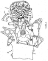
- FIG. 3 shows a side cross-sectional view of the same.
- the unit swing type of engine 10 of this embodiment is to be mounted on a scooter type of motorcycle (motor vehicle) (not shown) and constituted with; a forced air cooled type of four-stroke cycle engine (hereinafter simply called an engine) 1, and a transmission mechanism including a V-belt type of automatic transmission 2 disposed in a transmission case 3 extending from the left side of the crankcase 1a of the engine 1 toward the rear of the vehicle body, all assembled in a compact unit.
- a transmission case cover 4 is attached using a bolt 5 onto the side opening of the transmission case 3.
- a belt chamber S is formed inside the transmission case 3 covered with the transmission case cover 4.
- the V-belt type of automatic transmission 2 is disposed in the belt chamber S.
- a soundproof cover 6 is attached using a plurality of bolts 7 onto the outside surface of the transmission case cover 4.
- a sponge-like sealing member 8 is interposed between both of the covers 4 and 6.
- the engine 1 has a single cylinder 5 bored in a cylinder body 104 directed generally horizontally forward of the vehicle body of a scooter type of motorcycle.
- a piston 60 is slidably disposed in the cylinder 5.
- the piston 60 is connected through a connecting rod 8 to a crankshaft 13 rotatably disposed in the vehicle width direction.
- a cylinder head 9 placed to cover the cylinder body 104 has an intake port 10 and an exhaust port 11 bored in upper and lower positions of the cylinder head 9.
- the intake and exhaust ports 10 and 11 are opened and closed according to appropriate timing with intake and exhaust valves 12 and 131 so that gas in the cylinder 5 is exchanged as required.
- the intake and exhaust valves 12 and 131 are slidably inserted into and held with valve guides 14 and 15 press-fitted into the cylinder head 9, and urged toward the closing side with springs 16 and 17, and their tops are in contact with one side ends of rocker arms 18 and 19.
- the rocker arms 18 and 19 are pivoted for swinging about their middle parts with shafts 20 and 21.
- the other side ends of the rocker arms 18 and 19 are in contact with cams formed integrally with a camshaft 22.
- a chain sprocket (not shown) is attached to one end of the camshaft 22.
- An endless cam chain 30 is routed around between the chain sprocket and another sprocket 29 attached to the middle part of the crankshaft 13 (See FIG. 2).
- crankshaft 13 The rotation of the crankshaft 13 is transmitted through the sprocket 29, the cam chain 30, and the chain sprocket (not shown) attached to the camshaft 22.
- the camshaft 22 is driven at a specified speed (half the speed of the crankshaft 13)
- the intake and exhaust valves 12 and 131 are driven by the rocker arms 18, 19, to open and dose the intake and exhaust ports 10 and 11 according to appropriate timing. In this way, gas in the cylinder 5 is exchanged as required.
- crankshaft 13 is rotatably supported with paired right and left bearings 31.
- a cooling fan 32 is attached to one (right) end of the crankshaft 13.
- a dynamo 33 is disposed inside the cooling fan 32.
- a starter wheel 34, and a drive pulley 35 as a component of the V-belt type of automatic transmission 2, are attached to the other (left) end of the crankshaft 13.
- the drive pulley 35 is constituted with a fixed sheave 35a secured to one end of the crankshaft 13 and a movable sheave 35b supported to be slidable along the crankshaft 13.
- a plural number of centrifugal weights 37 are housed to be movable in radial directions in the space between the movable sheave 35b and a cam plate 36 secured to the crankshaft 13.
- a plural number of cooling fins 38 are formed integrally with the fixed sheave 35a of the drive pulley 35 to serve as a cooling fan.
- an intake pipe 312 connected to the intake port 10 is attached to the upper part of the cylinder head 9.
- a carburetor and an air cleaner are connected to the intake pipe 312.
- An exhaust pipe (not shown) is attached to the exhaust port 11 which is open to the lower part of the cylinder head 9.
- a muffler (not shown) is attached to the exhaust pipe.
- the entire engine 1 constituted as described above is enclosed with an air shroud 40 made of a plastic material.
- Part of the air shroud 40 opposite the cooling fan 32 is provided with a cooling air introducing opening 40a coaxially with the crankshaft 13.
- the air shroud 40 is provided, at its front part, with a plug hole 40b which is open to the obliquely side direction and behind it, with a round hole 40c for checking the top dead center.
- An ignition plug (not shown) is passed through the plug hole 40b and screwed into the cylinder head 9.
- a rubber cap 41 is removably fitted into the round hole 40c for checking the top dead center.
- a driven shaft 42 As shown in FIG. 1, in the rear part of the crankcase 3 are disposed a driven shaft 42, an intermediate shaft (not shown), and an output (wheel) shaft 43, parallel to each other.
- a driven pulley 44 and a centrifugal clutch 45 are attached to the driven shaft 42.
- a hollow shaft 46 On the driven shaft 42 is rotatably supported a hollow shaft 46. To the inside end of the hollow shaft 46 is attached the fixed sheave 44a of the driven pulley 44. A movable sleeve 47 is slidably fitted over the hollow shaft 46. The movable sheave 44b of the driven pulley 44 is attached to the inside end of the movable sleeve 47. The movable sheave 44b is urged toward the fixed sheave 44a with a spring 48 compression-installed between the centrifugal clutch 45 and the movable sheave 44b itself.
- the V-belt type of automatic transmission 2 is constituted with; the driven pulley 44 constituted with the fixed sheave 44a and the movable sheave 44b, the drive pulley 35 disposed on the crankshaft 13, and an endless V-belt 49 routed around between the drive pulley 35 and the driven pulley 44.
- the centrifugal clutch 45 is constituted with a clutch inside member 45a fixed to the outside end of the hollow shaft 46 and a clutch outside member 45b which is in a form of drum and secured at the outer end of driven shaft 42.
- a drive gear 50 is integrally formed with the inside end of the driven shaft 42.
- a drive gear and a driven gear of a large and a small diameters respectively are attached to an intermediate shaft (not shown).
- the driven gear of the intermediate shaft meshes with the drive gear 50.
- the drive gear (not shown) of the intermediate shaft meshes with the large diameter driven gear 51 attached to the output shaft 43.
- a rear wheel 52 of the scooter type of motorcycle is attached to the end of the output shaft 43 protruding out of the transmission case 3.
- a kick lever 53 for kick-starting is shown in FIG. 1.
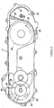
- FIG. 4 is an inside view of the transmission case cover.
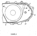
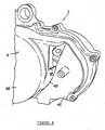
- FIG. 5 is an outside view of the transmission case cover.
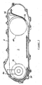
- FIG. 6 is a side view of the rear part of the transmission case cover with a soundproof cover attached.
- FIG. 7 shows the air flow in the belt chamber.
- FIG. 8 is a view, as seen obliquely from above, of the rear part of the transmission case cover.
- a vertical boss 4A is integrally formed with the forward upper outside surface of the transmission case cover.
- the top end surface of the boss 4A is open to be a cooling air inlet 4a.
- the bottom end surface of the boss 4A is open to the belt chamber S formed inside the transmission case cover 4.
- the front arcuate portion of. the outside wall of the transmission case cover 4 forms an air introducing wall 4b.
- a spiral-shaped air (introducing or guiding) passage 54 with its cross-sectional area gradually increasing in the rotation (arrow in the figure) direction of the drive pulley 35 is formed between the air introducing wall 4b and the drive pulley 35 of the V-belt type of automatic transmission 2.
- a stepped portion is formed with; the first outside wall surface 4B of the transmission case cover 4 covering one side ends of the driven shaft 42 and the driven pulley 44, the second outside wall surface 4C covering one side end in the vehicle width direction of the output shaft 43, and the third outside wall surface 4D extending in the vehicle width direction between the wall surfaces 4A and 4B.
- the third outside wall surface 4D is made to extend along the contour of the driven pulley 44 from below the lower edge to the rear central part of the driven pulley 44 to form an air (introducing or guiding) passage 55.
- a cooling air outlet 56 (the broken line-hatched part in FIGs.
- the cooling air outlet 56 is open rearward through part of the third outside wall 3D above and behind the driven pulley 44.
- the air introducing passage 55 is formed with its cross-sectional area gradually increasing in the rotation (arrows in FIGs. 4 and 5) direction of the driven pulley 44.
- the rear part of the third outside wall surface 3D of the transmission case cover 4 is provided with a generally arcuate rib 4e.
- a space S1 is formed between both of the covers 4 and 6.
- the cooling air outlet 56 formed in the transmission case cover 4 is open in the upper part of the space S1 which is open downward to the atmosphere through a cooling air outlet 57.
- the centrifugal clutch 45 is in the off state, the rotation of the hollow shaft 46 and the clutch inside member 45a of the centrifugal clutch 45 is not transmitted to the driven shaft 42, and the hollow shaft 46 and the clutch inside member 45a of the centrifugal clutch 45 rotate freely on the driven shaft 42.
- the magnitude of the centrifugal force working on the centrifugal weights 37 is in proportion to the rotation speed of the crankshaft 13. According to the magnitude of the centrifugal force, the centrifugal weights 37 move radially outward along the contact surface of the cam plate 36 to move the movable sheave 35b of the drive pulley 35 toward the fixed sheave 35a, and increase the girdling diameter of the V-belt 49 around the drive pulley 35. In contrast, the girdling diameter of the V-belt 49 around the driven pulley 44 decreases. As a result, the speed ratio of the driven shaft 42 to the crankshaft 13 increases gradually, to gradually increase the rotation speed of the driven shaft 42. In this way, automatic speed change is performed.
- the fixed sheave 35a of the drive pulley 35 serves also as a cooling fan and draws cooling air through the cooling air inlet 4a of the transmission case cover 4 into the belt chamber S.
- the cooling air introduced into the belt chamber S is stirred with the drive pulley 35 rotating in the direction of the arrow shown in FIG. 7 and flows in the direction of the arrow shown through the air introducing passage 54 formed around the drive pulley 35.
- the air introducing passage 54 is formed spirally with its cross-sectional area gradually increasing in the direction of the cooling air flow. Therefore, the velocity of the cooling air passing through the air introducing passage 54 decreases gradually and its dynamic pressure is held low.
- the cooling air with its velocity reduced as described above flows as shown with the arrow in FIG. 7 through the belt chamber S toward the rear of the vehicle body to cool the belt chamber S, stirred with the driven pulley 44 rotating in the arrow direction, flows through the air introducing passage 55 in the arrow direction obliquely rear upward and discharged out of the belt chamber S through the cooling air outlet 56 formed ahead of the flow direction, flows into the space S1 formed between the covers 4 and 6 to expand, flows down through the space S1, and finally discharged to the atmosphere through the cooling air outlet 57 (See FIG. 6) .
- the air introducing passage 55 like the air introducing passage 54, is formed in the spiral shape with its cross-sectional area gradually increasing in the direction of the cooling air flow. Therefore, the velocity of the cooling air passing through the air introducing passage 55 decreases gradually and its dynamic pressure is held low.
- the air introducing passages 54 and 55 of the spiral shape are formed around the drive and driven pulleys 35 and 44 of the V-belt type of automatic transmission 2 respectively, the cooling air velocity is reduced as the air flows through the spiral-shaped air introducing passages 54 and 55 having gradually increasing cross-sectional areas respectively.
- the cooling air with the reduced velocity flows without changing greatly its flow direction in the tangential direction through the air introducing passage 55 around the driven pulley 44 and out of the belt chamber S through the cooling air outlet 56. Therefore, the flow energy loss of the cooling air in the belt chamber s is held low, the cooling efficiency is enhanced, and power loss is held low.
- the air introducing passage 55 is formed by utilizing the third outside wall surface 4D constituting the stepped portion of the transmission case cover 4, cooling efficiency is enhanced in comparison with forming the air introducing passage 55 with a rib, while holding down the increase in the weight of the transmission case cover 4, and securing the rigidity required of the transmission case cover 4.
- this embodiment is arranged that the rearward-opening cooling air outlet is formed in the stepped portion located higher than the driven wheel 42 and deeper than the first outside wall surface 4B of the transmission case cover 4.
- the space S1 serving as an expansion chamber is formed with the soundproof cover 6 in the downstream position from the cooling air outlet 56, it is possible to reduce noise while more effectively preventing water and dust from entering the belt chamber S.
- cooling air is introduced through the cooling air introducing inlet 40a bored in the right side wall of the air shroud 40 into the interior of the air shroud 40 as the cooling fan 32 is rotated as described above, and the cooling air flows through the air shroud 40 toward the front of the vehicle body and cools various parts of the engine 1 including the cylinder body 104 and the cylinder head 9.
- the above description relates to a transmission case cover structure of a unit swing type of engine.
- the unit swing type of engine is constituted with a V-belt type of automatic transmission, which in turn is constituted with a drive pulley attached to a crankshaft extending in the vehicle width direction, a driven pulley attached to a driven shaft extending in the vehicle width direction behind the crankshaft, and an endless V-belt fitted around and stretched between the drive and driven pulleys.
- the unit swing type of engine is housed in a belt chamber formed by covering with a transmission case cover a side opening of a transmission case protruding in the vehicle width direction from one side end of the crankcase of the engine.
- the transmission case cover structure is constituted with the following features:
- a stepped portion is formed with; a first outside wall surface of the transmission case cover covering the one side ends in the vehicle width direction of the driven shaft and the driven pulley, a second outside wall surface covering the one side end in the vehicle width direction of the output shaft, and a third outside wall surface extending in the vehicle width direction to interconnect the first and second outside wall surfaces.
- the third outside wall surface is formed around the contour of the driven pulley to form an air introducing passage around the driven pulley.
- a cooling air outlet is formed in part of the outside wall on the extended tangent line of the air introducing passage.
- the outside wall surface is formed around the contour of the driven pulley to form an air introducing passage around the driven pulley and a cooling air outlet is formed in part of the outside wall on an extended tangent line of the air introducing passage, the cooling air flows through the air introducing passage without greatly changing its flow direction in the tangential direction of the driven pulley and flows out of the belt chamber through the cooling air outlet. This reduces the flow energy loss of the cooling air in the belt chamber, enhances the cooling efficiency in the belt chamber, and reduces power loss.
- the cooling efficiency is enhanced, in comparison with the case of forming the air introducing passage with a rib, while holding down the increase in the weight of the transmission case cover and securing rigidity required for the transmission case cover.
- the third outside wall surface of the transmission case cover is made to extend around the contour of the driven pulley, from below the lower edge to the rear central part of the driven pulley, to form the air introducing passage around the driven pulley, and the cooling air outlet open toward the rear is formed in part of the outside wall above behind the driven pulley.
- cooling air outlet is made to be open toward the rear in the stepped portion located deeper than the first outside wall surface of the transmission case cover, water is prevented from entering the belt chamber and the flow energy loss of the cooling air is further reduced to further enhance the cooling effciency.
- a soundproof cover is provided to cover the outside wall surface of the transmission case cover to form a space between the soundproof cover and the transmission case cover, and the cooling air outlet is made open to the space.
- a transmission means especially for a unit type of engine comprises a V-belt type of automatic transmission 2 with a drive pulley 35, a driven pulley 44 and an endless V-belt 49 fitted around said drive and driven pulley 35,44.
- Said drive and driven pulley 35,44 and said endless V-belt 49 are housed in a belt chamber S formed by a transmission case 3.
- a transmission case cover 4 is provided on a side opening of said transmission case 3, wherein said transmission case cover 4 defines an air passage 55 around said driven pulley 44.
- the air passage 55 gradually increases in direction of a cooling air flow.
- Said transmission case cover 4 comprises a first outside wall surface 4B covering the driven pulley 44 and a third outside wall surface 4D extending from said first outside wall surface 4B and formed around a contour of said driven pulley 44 to form said air passage 55 around said driven pulley 44.
- a cooling air outlet 56 is formed on said third outside wall surface 4D.
- Said third outside wall surface 4D is formed to cover a lower edge area of the driven pulley 44 and extends to cover a rear edge of said driven pulley 44 to form said air passage 55 around said driven pulley 44.
- Said cooling air outlet 56 is formed in a rear part of said third outside wall surface above and behind said rear edge of the driven pulley 44. Said cooling air outlet 56 is formed on said third outside wall surface 4D on an extended tangent line of said air introducing passage 55.
- Said driven pulley 44 is connected with a driven shaft 42 and an output shaft 43 is provided which is spaced from driven shaft 42 and connected therewith.
- Said transmission case cover 4 comprises a second outside wall surface 4C covering the output shaft 43 and said third outside wall surface 4D is interconnecting said first outside wall surface 4B and said-second outside wall surface 4B to constitute a stepped portion of the transmission case cover 4.
- a soundproof cover 6 is provided to cover said outside wall surfaces of the transmission case cover 4, wherein a space S1 is formed between said soundproof cover 6 and the transmission case cover 4 and said cooling air outlet 56 is made open to said space S1.
- An arcuate rib 4e is provided on the second outside wall surface 4C to define said space S1, wherein said cooling air outlet 56 is open in an upper part of said space S1 and said space S1 is provided with a further cooling air outlet 57 in a downward direction.
- a cooling air inlet 4a is provided on said transmission case 3 and an further air passage 54 is provided around said drive pulley 35 from said cooling air inlet 4a and a cross-sectional area of said air passage 54 gradually increases in a direction of a cooling air flow.
- the above described embodiment also teaches a motor vehicle with an engine 1 especially for a unit type of engine, a vehicle body and a transmission means with a V-belt type of automatic transmission 2.
- Said transmission means is constructed as mentioned above, wherein said V-belt type of automatic transmission 2 is provided with a drive pulley 35, a driven pulley 44 and an endless V-belt 49 fitted around said drive and driven pulley 35,44, said drive and driven pulley 35,44 and said endless V-belt 49 are housed in a belt chamber S formed by a transmission case 3 and a transmission case cover 4 provided on a side opening of said transmission case 3 in the width direction of the vehicle body, wherein said transmission case cover 4 defines an air passage 55 around said driven pulley 44.
- Said transmission case cover 4 comprises a first outside wall surface 4B covering the driven pulley 44 in the width direction of the vehicle body and a third outside wall surface 4D extending in the width direction of the vehicle body from said first outside wall surface 4B and formed around a contour of said driven pulley 44 to form said air passage 55 around said driven pulley 44, wherein a cooling air outlet 56 is formed on said third outside wall surface 4D.
- Said third outside wall surface 4D is formed to cover a lower edge area of the driven pulley 44 and extends to cover a rear edge of said driven pulley 44 to form said air passage 55 around said driven pulley 44, wherein said cooling air outlet 56 is formed in a rear part of said third outside wall surface above and behind said rear edge of the driven pulley 44.
- said driven pulley 44 is connected with a driven shaft 42 extending in the width direction of the vehicle body and an output shaft 43 extending in the width direction of the vehicle body is provided which is spaced from driven shaft 42 and connected therewith, and said transmission case cover 4 comprises a second outside wall surface 4C covering the output shaft 43 in the width direction of the vehicle body and said third outside wall surface 4D is interconnecting said first outside wall surface 4B and said second outside wall surface 4B to constitute a stepped portion of the transmission case cover 4.
- the soundproof cover 6 is provided to cover said outside wall surfaces of the transmission case cover 4 in the width direction of the vehicle body, wherein a space S1 is formed between said soundproof cover 6 and the transmission case cover 4 and said cooling air outlet 56 is made open to said space S1.
Landscapes
- Engineering & Computer Science (AREA)
- General Engineering & Computer Science (AREA)
- Mechanical Engineering (AREA)
- Chemical & Material Sciences (AREA)
- Combustion & Propulsion (AREA)
- Transportation (AREA)
- General Details Of Gearings (AREA)
Abstract
Description
- This invention relates to a transmission means especially for a unit type of engine with a V-belt type of automatic transmission and a motor vehicle with an engine especially for a unit type of engine, a vehicle body and a transmission means with a V-belt type of automatic transmission.
- The unit swing type of engine for example mounted on a small-sized scooter type of motorcycle is constituted as a single unit assembling together an engine as a driving power source, and a transmission mechanism including a V-belt type of automatic speed reduction mechanism, etc. in a transmission case.
- Such a unit swing type of engine employs a constitution shown in FIG. 9: a V-belt type of
automatic transmission 102 is accommodated in a belt chamber S covered with atransmission case cover 104, and the belt chamber S is cooled with cooling air introduced into the belt chamber S. - The V-belt type of
automatic transmission 102 is constituted with adrive pulley 135, a driven pulley 144, and an endless V-belt 149 fitted around and stretched between the drive and driven pulleys. The belt chamber S is provided in its front lower corner with a cooling air inlet 104a open in the direction obliquely down forward (left in the figure) and in its rear part with acooling air outlet 136 open in the downward direction. Cooling air introduced with a cooling fan (not shown) provided on thedrive pulley 135 of the V-belt type ofautomatic transmission 102 from the cooling air inlet 104a into the belt chamber S, flows in the direction of the arrow, cools the belt chamber S, and flows out of the belt chamber S through thecooling air outlet 136. - The conventional constitution shown in FIG. 9, however, has problems: Since the width of the flow passage formed between the outside wall of the
transmission case cover 104 and thedrive pulley 135 of the V-belt type ofautomatic transmission 102 is constant, the velocity in the belt chamber S of the cooling air introduced into the belt chamber S is great. Therefore, the cooling air having a great velocity is bent by a large angle in a Ushape and discharged out of thecooling air outlet 136. This causes problems of; a great flow energy loss of the cooling air, poor cooling efficiency in thebelt chamber 5, and a great power loss. - It is an objective of the present invention to provide a transmission means especially for a unit type of engine with a V-belt type of automatic transmission and a motor vehicle with an engine, especially for a unit type of engine, a vehicle body and a transmission means with a V-belt type of automatic transmission having a high cooling efficiency in the belt chamber.
- According to a first aspect of the present invention said objective is solved by a transmission means especially for a unit type of engine with a V-belt type of automatic transmission provided with a drive pulley, a driven pulley and an endless V-belt fitted around said drive and driven pulley, said drive and driven pulley and said endless V-belt are housed in a belt chamber formed by a transmission case and a transmission case cover provided on a side opening of said transmission case, wherein said transmission case cover defines an air passage around said driven pulley.
- It is a special advantage of the invention to provide a transmission means which can reduce power loss.
- Preferably, the air passage gradually increases in direction of a cooling air flow.
- According to a preferred embodiment of the transmission means, said transmission case cover comprises a first outside wall surface covering the driven pulley and a third outside wall surface extending from said first outside wall surface and formed around a contour of said driven pulley to form said air passage around said driven pulley, wherein a cooling air outlet is formed on said third outside wall surface.
- Said third outside wall surface is formed to cover a lower edge area of the driven pulley and extends to cover a rear edge of said driven pulley to form said air passage around said driven pulley, wherein said cooling air outlet is formed in a rear part of said third outside wall surface above and behind said rear edge of the driven pulley.
- Preferably, said cooling air outlet is formed on said third outside wall surface on an extended tangent line of said air introducing passage.
- According to a preferred embodiment of the transmission means, said driven pulley is connected with a driven shaft and an output shaft is provided which is spaced from driven shaft and connected therewith, and said transmission case cover comprises a second outside wall surface covering the output shaft and said third outside wall surface is interconnecting said first outside wall surface and said second outside wall surface to constitute a stepped portion of the transmission case cover.
- According to a preferred embodiment, a soundproof cover is provided to cover said outside wall surfaces of the transmission case cover, wherein a space is formed between said soundproof cover and the transmission case cover and said cooling air outlet is made open to said space.
- Preferably, an arcuate rib is provided on the second outside wall surface to define said space, wherein said cooling air outlet is open in an upper part of said space and said space is provided with a further cooling air outlet in a downward direction.
- According to a preferred embodiment, a cooling air inlet is provided on said transmission case and an further air passage is provided around said drive pulley from said cooling air inlet and a cross-sectional area of said air passage gradually increases in a direction of a cooling air flow.
- According to a second aspect of the present invention said objective is solved by a motor vehicle with an engine, especially for a unit type of engine, a vehicle body and a transmission means with a V-belt type of automatic transmission provided with a drive pulley, a driven pulley and an endless V-belt fitted around said drive and driven pulley, said drive and driven pulley and said endless V-belt are housed in a belt chamber formed by a transmission case and a transmission case cover provided on a side opening of said transmission case in the width direction of the vehicle body, wherein said transmission case cover defines an air passage around said driven pulley.
- It is a special advantage of the invention to provide a motor vehicle wherein power loss can be reduced.
- According to a preferred embodiment of the motor vehicle, said transmission case cover comprises a first outside wall surface covering the driven pulley in the width direction of the vehicle body and a third outside wall surface extending in the width direction of the vehicle body from said first outside wall surface and formed around a contour of said driven pulley to form said air passage around said driven pulley, wherein a cooling air outlet is formed on said third outside wall surface.
- Said third outside wall surface is formed to cover a lower edge area of the driven pulley and extends to cover a rear edge of said driven pulley to form said air passage around said driven pulley, wherein said cooling air outlet is formed in a rear part of said third outside wall surface above and behind said rear edge of the driven pulley. Said cooling air outlet is formed on said third outside wall surface on an extended tangent line of said air introducing passage.
- According to a preferred embodiment of the motor vehicle said driven pulley is connected with a driven shaft extending in the width direction of the vehicle body and an output shaft extending in the width direction of the vehicle body is provided which is spaced from driven shaft and connected therewith, and said transmission case cover comprises a second outside wall surface covering the output shaft in the width direction of the vehicle body and said third outside wall surface is interconnecting said first outside wall surface and said second outside wall surface to constitute a stepped portion of the transmission case cover.
- Preferably, a soundproof cover is provided to cover said outside wall surfaces of the transmission case cover in the width direction of the vehicle body, wherein a space is formed between said soundproof cover and the transmission case cover and said cooling air outlet is made open to said space.
- Other preferred embodiments of the present invention are laid down in further dependent claims.
- In the following, the present invention is explained in greater detail with respect to several embodiments thereof in conjunction with the accompanying drawings, wherein:
- FIG. 1 is a cross-sectional plan view of a unit swing type of engine;
- FIG. 2 is a cross-sectional plan view of the four-stroke cycle engine portion of the unit swing type of engine;
- FIG. 3 is a cross-sectional side view of the four-stroke cycle engine portion of the unit swing type of engine;
- FIG. 4 is an inside view of a transmission case cover;
- FIG. 5 is an external view of the transmission case cover;
- FIG. 6 a side view of the rear part of the transmission case cover with another cover attached;
- FIG. 7 is a cooling air flow diagram in the transmission case cover structure;
- FIG. 8 is a perspective view of the rear part of the transmission case; and
- FIG. 9 is a cooling air flow diagram in a conventional transmission case cover structure.
-
- An embodiment will be described below in reference to the appended figures.
- FIG. 1 is a plan view, partially in cross section, of a unit swing type of engine. FIG. 2 is a plan view in cross section of a four-stroke cycle engine portion of the unit swing type of engine. FIG. 3 shows a side cross-sectional view of the same.
- The unit swing type of
engine 10 of this embodiment is to be mounted on a scooter type of motorcycle (motor vehicle) (not shown) and constituted with; a forced air cooled type of four-stroke cycle engine (hereinafter simply called an engine) 1, and a transmission mechanism including a V-belt type ofautomatic transmission 2 disposed in a transmission case 3 extending from the left side of the crankcase 1a of the engine 1 toward the rear of the vehicle body, all assembled in a compact unit. - As shown in FIG. 1, a
transmission case cover 4 is attached using abolt 5 onto the side opening of the transmission case 3. A belt chamber S is formed inside the transmission case 3 covered with thetransmission case cover 4. The V-belt type ofautomatic transmission 2 is disposed in the belt chamber S. - A
soundproof cover 6 is attached using a plurality ofbolts 7 onto the outside surface of thetransmission case cover 4. A sponge-like sealing member 8 is interposed between both of thecovers - Here, constitution of the engine 1 will be roughly described.
- As shown in FIG. 3, the engine 1 has a
single cylinder 5 bored in acylinder body 104 directed generally horizontally forward of the vehicle body of a scooter type of motorcycle. Apiston 60 is slidably disposed in thecylinder 5. Thepiston 60 is connected through a connecting rod 8 to acrankshaft 13 rotatably disposed in the vehicle width direction. - A
cylinder head 9 placed to cover thecylinder body 104 has anintake port 10 and an exhaust port 11 bored in upper and lower positions of thecylinder head 9. The intake andexhaust ports 10 and 11 are opened and closed according to appropriate timing with intake andexhaust valves 12 and 131 so that gas in thecylinder 5 is exchanged as required. - As shown in FIG. 3, the intake and
exhaust valves 12 and 131 are slidably inserted into and held with valve guides 14 and 15 press-fitted into thecylinder head 9, and urged toward the closing side with springs 16 and 17, and their tops are in contact with one side ends ofrocker arms 18 and 19. Therocker arms 18 and 19 are pivoted for swinging about their middle parts with shafts 20 and 21. The other side ends of therocker arms 18 and 19 are in contact with cams formed integrally with a camshaft 22. - A chain sprocket (not shown) is attached to one end of the camshaft 22. An
endless cam chain 30 is routed around between the chain sprocket and anothersprocket 29 attached to the middle part of the crankshaft 13 (See FIG. 2). - The rotation of the
crankshaft 13 is transmitted through thesprocket 29, thecam chain 30, and the chain sprocket (not shown) attached to the camshaft 22. When the camshaft 22 is driven at a specified speed (half the speed of the crankshaft 13), the intake andexhaust valves 12 and 131 are driven by therocker arms 18, 19, to open and dose the intake andexhaust ports 10 and 11 according to appropriate timing. In this way, gas in thecylinder 5 is exchanged as required. - As shown in FIG. 2 in detail, the
crankshaft 13 is rotatably supported with paired right andleft bearings 31. Acooling fan 32 is attached to one (right) end of thecrankshaft 13. A dynamo 33 is disposed inside thecooling fan 32. Astarter wheel 34, and adrive pulley 35 as a component of the V-belt type ofautomatic transmission 2, are attached to the other (left) end of thecrankshaft 13. - The
drive pulley 35 is constituted with a fixedsheave 35a secured to one end of thecrankshaft 13 and amovable sheave 35b supported to be slidable along thecrankshaft 13. A plural number ofcentrifugal weights 37 are housed to be movable in radial directions in the space between themovable sheave 35b and acam plate 36 secured to thecrankshaft 13. A plural number ofcooling fins 38 are formed integrally with the fixedsheave 35a of thedrive pulley 35 to serve as a cooling fan. - As shown in FIG. 3, an
intake pipe 312 connected to theintake port 10 is attached to the upper part of thecylinder head 9. A carburetor and an air cleaner (both not shown) are connected to theintake pipe 312. An exhaust pipe (not shown) is attached to the exhaust port 11 which is open to the lower part of thecylinder head 9. A muffler (not shown) is attached to the exhaust pipe. - The entire engine 1 constituted as described above is enclosed with an
air shroud 40 made of a plastic material. Part of theair shroud 40 opposite the coolingfan 32 is provided with a coolingair introducing opening 40a coaxially with thecrankshaft 13. As shown in FIG. 2, theair shroud 40 is provided, at its front part, with a plug hole 40b which is open to the obliquely side direction and behind it, with around hole 40c for checking the top dead center. An ignition plug (not shown) is passed through the plug hole 40b and screwed into thecylinder head 9. Arubber cap 41 is removably fitted into theround hole 40c for checking the top dead center. - Next will be described the constitution of the transmission mechanism of the unit swing type of
engine 10. - As shown in FIG. 1, in the rear part of the crankcase 3 are disposed a driven shaft 42, an intermediate shaft (not shown), and an output (wheel)
shaft 43, parallel to each other. A drivenpulley 44 and a centrifugal clutch 45 are attached to the driven shaft 42. - On the driven shaft 42 is rotatably supported a
hollow shaft 46. To the inside end of thehollow shaft 46 is attached the fixedsheave 44a of the drivenpulley 44. A movable sleeve 47 is slidably fitted over thehollow shaft 46. The movable sheave 44b of the drivenpulley 44 is attached to the inside end of the movable sleeve 47. The movable sheave 44b is urged toward the fixedsheave 44a with aspring 48 compression-installed between the centrifugal clutch 45 and the movable sheave 44b itself. The V-belt type ofautomatic transmission 2 is constituted with; the drivenpulley 44 constituted with the fixedsheave 44a and the movable sheave 44b, thedrive pulley 35 disposed on thecrankshaft 13, and an endless V-belt 49 routed around between thedrive pulley 35 and the drivenpulley 44. - The centrifugal clutch 45 is constituted with a clutch inside member 45a fixed to the outside end of the
hollow shaft 46 and a clutch outsidemember 45b which is in a form of drum and secured at the outer end of driven shaft 42. - A drive gear 50 is integrally formed with the inside end of the driven shaft 42. A drive gear and a driven gear of a large and a small diameters respectively are attached to an intermediate shaft (not shown). The driven gear of the intermediate shaft meshes with the drive gear 50. The drive gear (not shown) of the intermediate shaft meshes with the large diameter driven
gear 51 attached to theoutput shaft 43. Arear wheel 52 of the scooter type of motorcycle is attached to the end of theoutput shaft 43 protruding out of the transmission case 3. Akick lever 53 for kick-starting is shown in FIG. 1. - The constitution of the transmission case cover will be now described in reference to FIGs. 4 to 8. FIG. 4 is an inside view of the transmission case cover. FIG. 5 is an outside view of the transmission case cover. FIG. 6 is a side view of the rear part of the transmission case cover with a soundproof cover attached. FIG. 7 shows the air flow in the belt chamber. FIG. 8 is a view, as seen obliquely from above, of the rear part of the transmission case cover.
- As shown in FIG. 5, a
vertical boss 4A is integrally formed with the forward upper outside surface of the transmission case cover. The top end surface of theboss 4A is open to be a coolingair inlet 4a. The bottom end surface of theboss 4A is open to the belt chamber S formed inside thetransmission case cover 4. - The front arcuate portion of. the outside wall of the transmission case cover 4 forms an
air introducing wall 4b. A spiral-shaped air (introducing or guiding)passage 54 with its cross-sectional area gradually increasing in the rotation (arrow in the figure) direction of thedrive pulley 35 is formed between theair introducing wall 4b and thedrive pulley 35 of the V-belt type ofautomatic transmission 2. - As shown in FIGs. 5 and 8, a stepped portion is formed with; the first
outside wall surface 4B of the transmission case cover 4 covering one side ends of the driven shaft 42 and the drivenpulley 44, the second outside wall surface 4C covering one side end in the vehicle width direction of theoutput shaft 43, and the thirdoutside wall surface 4D extending in the vehicle width direction between the wall surfaces 4A and 4B. The thirdoutside wall surface 4D is made to extend along the contour of the drivenpulley 44 from below the lower edge to the rear central part of the drivenpulley 44 to form an air (introducing or guiding)passage 55. A cooling air outlet 56 (the broken line-hatched part in FIGs. 4 and 5) is formed in part of the thirdoutside wall 4D on an extended tangent line of theair introducing passage 55. The coolingair outlet 56 is open rearward through part of the third outside wall 3D above and behind the drivenpulley 44. Theair introducing passage 55 is formed with its cross-sectional area gradually increasing in the rotation (arrows in FIGs. 4 and 5) direction of the drivenpulley 44. - As shown in FIGs. 5 and 8, the rear part of the third outside wall surface 3D of the
transmission case cover 4 is provided with a generallyarcuate rib 4e. - When the outside surface of the
transmission case cover 4 is covered with thesoundproof cover 6 as shown in FIG. 6, a space S1 is formed between both of thecovers air outlet 56 formed in thetransmission case cover 4 is open in the upper part of the space S1 which is open downward to the atmosphere through a coolingair outlet 57. - Next will be described the function of the unit swing type of
engine 10 constituted as described above. - When the engine 1 of the unit swing type of
engine 10 is started as thekick lever 53 or a starter button (not shown) is operated and thecrankshaft 13 rotates, the coolingfan 32 and thedynamo 33 both attached coaxially to thecrankshaft 13 rotate together. At the same time, the rotation of thecrankshaft 13 is transmitted through thedrive pulley 35 of the V-belt type ofautomatic transmission 2, the V-belt 49, and the drivenpulley 44 to thehollow shaft 46. Thehollow shaft 46 and the clutch inside member 45a of the centrifugal clutch 45 secured to thehollow shaft 46 are driven together to rotate. - When the rotation speed of the
crankshaft 13 is low, the centrifugal force working on thecentrifugal weights 37 rotating together with thecrankshaft 13 is small, and thecentrifugal weights 37 remain unmoved in the position shown in FIGs. 1 and 2. At this time, themovable sheave 35b of thedrive pulley 35 also remains in the position shown in the figures and the girdling diameter of the V-belt 49 around thedrive pulley 44 is also small. - Therefore, the girdling diameter of the V-
belt 49 around the drivenpulley 44 is held large, and the rotation of thecrankshaft 13 is reduced as it is transmitted to thehollow shaft 46 and the clutch inside member 45a of thecentrifugal clutch 45. In this way, while the rotation speed of the clutch inside member 45a of the centrifugal clutch 45 is small and the centrifugal force working on the clutch inside member 45a of the centrifugal clutch 45 is smaller than a specified value, the centrifugal clutch 45 is in the off state, the rotation of thehollow shaft 46 and the clutch inside member 45a of the centrifugal clutch 45 is not transmitted to the driven shaft 42, and thehollow shaft 46 and the clutch inside member 45a of the centrifugal clutch 45 rotate freely on the driven shaft 42. - After that, when the rotation speed of the
crankshaft 13 increases and the centrifugal force working on the clutch inside member 45a exceeds a specified value, the centrifugal clutch 45 is brought to the on state, the rotation of thehollow shaft 46 is transmitted through the centrifugal clutch 45 to the driven shaft 42, and the driven shaft 42 is driven to rotate. And the rotation of the driven shaft 42 is transmitted through a gear (not shown) attached to the intermediate shaft and a drivengear 51 attached to anoutput shaft 43, while being reduced in two stages, to theoutput shaft 43, and farther to therear wheel 52 attached to the out putshaft 43, 50 that the scooter type of motorcycle is driven. - The magnitude of the centrifugal force working on the
centrifugal weights 37 is in proportion to the rotation speed of thecrankshaft 13. According to the magnitude of the centrifugal force, thecentrifugal weights 37 move radially outward along the contact surface of thecam plate 36 to move themovable sheave 35b of thedrive pulley 35 toward the fixedsheave 35a, and increase the girdling diameter of the V-belt 49 around thedrive pulley 35. In contrast, the girdling diameter of the V-belt 49 around the drivenpulley 44 decreases. As a result, the speed ratio of the driven shaft 42 to thecrankshaft 13 increases gradually, to gradually increase the rotation speed of the driven shaft 42. In this way, automatic speed change is performed. - When the V-belt type of
automatic transmission 2 is operated as described above and thedrive pulley 35 is rotated, the fixedsheave 35a of thedrive pulley 35 serves also as a cooling fan and draws cooling air through the coolingair inlet 4a of the transmission case cover 4 into the belt chamber S. - The cooling air introduced into the belt chamber S is stirred with the
drive pulley 35 rotating in the direction of the arrow shown in FIG. 7 and flows in the direction of the arrow shown through theair introducing passage 54 formed around thedrive pulley 35. As described before, theair introducing passage 54 is formed spirally with its cross-sectional area gradually increasing in the direction of the cooling air flow. Therefore, the velocity of the cooling air passing through theair introducing passage 54 decreases gradually and its dynamic pressure is held low. - The cooling air with its velocity reduced as described above flows as shown with the arrow in FIG. 7 through the belt chamber S toward the rear of the vehicle body to cool the belt chamber S, stirred with the driven
pulley 44 rotating in the arrow direction, flows through theair introducing passage 55 in the arrow direction obliquely rear upward and discharged out of the belt chamber S through the coolingair outlet 56 formed ahead of the flow direction, flows into the space S1 formed between thecovers air introducing passage 55, like theair introducing passage 54, is formed in the spiral shape with its cross-sectional area gradually increasing in the direction of the cooling air flow. Therefore, the velocity of the cooling air passing through theair introducing passage 55 decreases gradually and its dynamic pressure is held low. - With this embodiment as described above, the
air introducing passages pulleys automatic transmission 2 respectively, the cooling air velocity is reduced as the air flows through the spiral-shapedair introducing passages air introducing passage 55 around the drivenpulley 44 and out of the belt chamber S through the coolingair outlet 56. Therefore, the flow energy loss of the cooling air in the belt chamber s is held low, the cooling efficiency is enhanced, and power loss is held low. - Since the
air introducing passage 55 is formed by utilizing the thirdoutside wall surface 4D constituting the stepped portion of thetransmission case cover 4, cooling efficiency is enhanced in comparison with forming theair introducing passage 55 with a rib, while holding down the increase in the weight of thetransmission case cover 4, and securing the rigidity required of thetransmission case cover 4. - Furthermore, this embodiment is arranged that the rearward-opening cooling air outlet is formed in the stepped portion located higher than the driven wheel 42 and deeper than the first
outside wall surface 4B of thetransmission case cover 4. As a result, it is possible to prevent water and dust from entering the belt chamber S, to further reduce flow energy loss of the cooling air, and to additionally enhance cooling efficiency. - Moreover, since the space S1 serving as an expansion chamber is formed with the
soundproof cover 6 in the downstream position from the coolingair outlet 56, it is possible to reduce noise while more effectively preventing water and dust from entering the belt chamber S. - On the part of the engine 1, cooling air is introduced through the cooling
air introducing inlet 40a bored in the right side wall of theair shroud 40 into the interior of theair shroud 40 as the coolingfan 32 is rotated as described above, and the cooling air flows through theair shroud 40 toward the front of the vehicle body and cools various parts of the engine 1 including thecylinder body 104 and thecylinder head 9. - The above description relates to a transmission case cover structure of a unit swing type of engine. The unit swing type of engine is constituted with a V-belt type of automatic transmission, which in turn is constituted with a drive pulley attached to a crankshaft extending in the vehicle width direction, a driven pulley attached to a driven shaft extending in the vehicle width direction behind the crankshaft, and an endless V-belt fitted around and stretched between the drive and driven pulleys. The unit swing type of engine is housed in a belt chamber formed by covering with a transmission case cover a side opening of a transmission case protruding in the vehicle width direction from one side end of the crankcase of the engine.
- The transmission case cover structure is constituted with the following features:
- A stepped portion is formed with; a first outside wall surface of the transmission case cover covering the one side ends in the vehicle width direction of the driven shaft and the driven pulley, a second outside wall surface covering the one side end in the vehicle width direction of the output shaft, and a third outside wall surface extending in the vehicle width direction to interconnect the first and second outside wall surfaces.
- The third outside wall surface is formed around the contour of the driven pulley to form an air introducing passage around the driven pulley.
- A cooling air outlet is formed in part of the outside wall on the extended tangent line of the air introducing passage.
- As a result, effects are provided that belt chamber cooling effect is enhanced and power loss is reduced.
- Therefore, since the outside wall surface is formed around the contour of the driven pulley to form an air introducing passage around the driven pulley and a cooling air outlet is formed in part of the outside wall on an extended tangent line of the air introducing passage, the cooling air flows through the air introducing passage without greatly changing its flow direction in the tangential direction of the driven pulley and flows out of the belt chamber through the cooling air outlet. This reduces the flow energy loss of the cooling air in the belt chamber, enhances the cooling efficiency in the belt chamber, and reduces power loss. Furthermore, since part of the outside wall, constituting the stepped portions, of the transmission case cover is utilized to form the air introducing passage, the cooling efficiency is enhanced, in comparison with the case of forming the air introducing passage with a rib, while holding down the increase in the weight of the transmission case cover and securing rigidity required for the transmission case cover.
- The third outside wall surface of the transmission case cover is made to extend around the contour of the driven pulley, from below the lower edge to the rear central part of the driven pulley, to form the air introducing passage around the driven pulley, and the cooling air outlet open toward the rear is formed in part of the outside wall above behind the driven pulley.
- Since the cooling air outlet is made to be open toward the rear in the stepped portion located deeper than the first outside wall surface of the transmission case cover, water is prevented from entering the belt chamber and the flow energy loss of the cooling air is further reduced to further enhance the cooling effciency.
- A soundproof cover is provided to cover the outside wall surface of the transmission case cover to form a space between the soundproof cover and the transmission case cover, and the cooling air outlet is made open to the space.
- Since the space functioning as an expansion chamber is formed in a downstream position from the cooling air outlet with the soundproof cover, noise is reduced while preventing more effectively water and dust from the entering the belt chamber.
- Regarding the above embodiment a transmission means especially for a unit type of engine is provided. Said embodiment comprises a V-belt type of
automatic transmission 2 with adrive pulley 35, a drivenpulley 44 and an endless V-belt 49 fitted around said drive and drivenpulley pulley belt 49 are housed in a belt chamber S formed by a transmission case 3. Atransmission case cover 4 is provided on a side opening of said transmission case 3, wherein saidtransmission case cover 4 defines anair passage 55 around said drivenpulley 44. Theair passage 55 gradually increases in direction of a cooling air flow. - Said
transmission case cover 4 comprises a firstoutside wall surface 4B covering the drivenpulley 44 and a thirdoutside wall surface 4D extending from said first outsidewall surface 4B and formed around a contour of said drivenpulley 44 to form saidair passage 55 around said drivenpulley 44. A coolingair outlet 56 is formed on said thirdoutside wall surface 4D. - Said third
outside wall surface 4D is formed to cover a lower edge area of the drivenpulley 44 and extends to cover a rear edge of said drivenpulley 44 to form saidair passage 55 around said drivenpulley 44. Said coolingair outlet 56 is formed in a rear part of said third outside wall surface above and behind said rear edge of the drivenpulley 44. Said coolingair outlet 56 is formed on said thirdoutside wall surface 4D on an extended tangent line of saidair introducing passage 55. - Said driven
pulley 44 is connected with a driven shaft 42 and anoutput shaft 43 is provided which is spaced from driven shaft 42 and connected therewith. Saidtransmission case cover 4 comprises a second outside wall surface 4C covering theoutput shaft 43 and said thirdoutside wall surface 4D is interconnecting said first outsidewall surface 4B and said-second outsidewall surface 4B to constitute a stepped portion of thetransmission case cover 4. - A
soundproof cover 6 is provided to cover said outside wall surfaces of thetransmission case cover 4, wherein a space S1 is formed between saidsoundproof cover 6 and thetransmission case cover 4 and saidcooling air outlet 56 is made open to said space S1. - An
arcuate rib 4e is provided on the secondoutside wall surface 4C to define said space S1, wherein said coolingair outlet 56 is open in an upper part of said space S1 and said space S1 is provided with a furthercooling air outlet 57 in a downward direction. - A cooling
air inlet 4a is provided on said transmission case 3 and anfurther air passage 54 is provided around saiddrive pulley 35 from said coolingair inlet 4a and a cross-sectional area of saidair passage 54 gradually increases in a direction of a cooling air flow. - Furthermore the above described embodiment also teaches a motor vehicle with an engine 1 especially for a unit type of engine, a vehicle body and a transmission means with a V-belt type of
automatic transmission 2. Said transmission means is constructed as mentioned above, wherein said V-belt type ofautomatic transmission 2 is provided with adrive pulley 35, a drivenpulley 44 and an endless V-belt 49 fitted around said drive and drivenpulley pulley belt 49 are housed in a belt chamber S formed by a transmission case 3 and a transmission case cover 4 provided on a side opening of said transmission case 3 in the width direction of the vehicle body, wherein saidtransmission case cover 4 defines anair passage 55 around said drivenpulley 44. - Said
transmission case cover 4 comprises a firstoutside wall surface 4B covering the drivenpulley 44 in the width direction of the vehicle body and a thirdoutside wall surface 4D extending in the width direction of the vehicle body from said first outsidewall surface 4B and formed around a contour of said drivenpulley 44 to form saidair passage 55 around said drivenpulley 44, wherein a coolingair outlet 56 is formed on said third outside wall surface 4D. Said thirdoutside wall surface 4D is formed to cover a lower edge area of the drivenpulley 44 and extends to cover a rear edge of said drivenpulley 44 to form saidair passage 55 around said drivenpulley 44, wherein said coolingair outlet 56 is formed in a rear part of said third outside wall surface above and behind said rear edge of the drivenpulley 44. - According to the motor vehicle, said driven
pulley 44 is connected with a driven shaft 42 extending in the width direction of the vehicle body and anoutput shaft 43 extending in the width direction of the vehicle body is provided which is spaced from driven shaft 42 and connected therewith, and saidtransmission case cover 4 comprises a second outside wall surface 4C covering theoutput shaft 43 in the width direction of the vehicle body and said thirdoutside wall surface 4D is interconnecting said first outsidewall surface 4B and said secondoutside wall surface 4B to constitute a stepped portion of thetransmission case cover 4. - The
soundproof cover 6 is provided to cover said outside wall surfaces of the transmission case cover 4 in the width direction of the vehicle body, wherein a space S1 is formed between saidsoundproof cover 6 and thetransmission case cover 4 and saidcooling air outlet 56 is made open to said space S1.
Claims (18)
- Transmission means especially for a unit type of engine with a V-belt type of automatic transmission (2) provided with a drive pulley (35), a driven pulley (44) and an endless V-belt (49) fitted around said drive and driven pulley (35,44), said drive and driven pulley (35,44) and said endless V-belt (49) are housed in a belt chamber (S) formed by a transmission case (3) and a transmission case cover (4) provided on a side opening of said transmission case (3), wherein said transmission case cover (4) defines an air passage (55) around said driven pulley (44).
- Transmission means according to claim 1, wherein the air passage (55) gradually increases in direction of a cooling air flow.
- Transmission means according to claim 1 or 2, wherein said transmission case cover (4) comprises a first outside wall surface (4B) covering the driven pulley (44) and a third outside wall surface (4D) extending from said first outside wall surface (4B) and formed around a contour of said driven pulley (44) to form said air passage (55) around said driven pulley (44), wherein a cooling air outlet (56) is formed on said third outside wall surface (4D).
- Transmission means according to claim 3, wherein said third outside wall surface (4D) is formed to cover a lower edge area of the driven pulley (44) and extends to cover a rear edge of said driven pulley (44) to form said air passage (55) around said driven pulley (44), wherein said cooling air outlet (56) is formed in a rear part of said third outside wall surface above and behind said rear edge of the driven pulley (44).
- Transmission means according to claim 3 or 4, wherein said cooling air outlet (56) is formed on said third outside wall surface (4D) on an extended tangent line of said air introducing passage (55).
- Transmission means according to at least one of the claims 3 to 5, wherein said driven pulley (44) is connected with a driven shaft (42) and an output shaft (43) is provided which is spaced from driven shaft (42) and connected therewith, and said transmission case cover (4) comprises a second outside wall surface (4C) covering the output shaft (43) and said third outside wall surface (4D) is interconnecting said first outside wall surface (4B) and said second outside wall surface (4B) to constitute a stepped portion of the transmission case cover (4).
- Transmission means according to at least one of the claims 3 to 6, wherein a soundproof cover (6) is provided to cover said outside wall surfaces of the transmission case cover (4), wherein a space (S1) is formed between said soundproof cover (6) and the transmission case cover (4) and said cooling air outlet (56) is made open to said space (S1).
- Transmission means according to claim 7, wherein an arcuate rib (4e) is provided on the second outside wall surface (4C) to define said space (S1), wherein said cooling air outlet (56) is open in an upper part of said space (S1) and said space (S1) is provided with a further cooling air outlet (57) in a downward direction.
- Transmission means according to at least one of the claims 1 to 8, wherein a cooling air inlet (4a) is provided on said transmission case (3) and an further air passage (54) is provided around said drive pulley (35) from said cooling air inlet (4a) and a cross-sectional area of said air passage (54) gradually increases in a direction of a cooling air flow.
- Motor vehicle with an engine (1) especially for a unit type of engine, a vehicle body and a transmission means with a V-belt type of automatic transmission (2) provided with a drive pulley (35), a driven pulley (44) and an endless V-belt (49) fitted around said drive and driven pulley (35,44), said drive and driven pulley (35,44) and said endless V-belt (49) are housed in a belt chamber (S) formed by a transmission case (3) and a transmission case cover (4) provided on a side opening of said transmission case (3) in the width direction of the vehicle body, wherein said transmission case cover (4) defines an air passage (55) around said driven pulley (44).
- Motor vehicle according to claim 10, wherein the air passage (55) gradually increases in direction of a cooling air flow.
- Motor vehicle according to claim 10 or 11, wherein said transmission case cover (4) comprises a first outside wall surface (4B) covering the driven pulley (44) in the width direction of the vehicle body and a third outside wall surface (4D) extending in the width direction of the vehicle body from said first outside wall surface (4B) and formed around a contour of said driven pulley (44) to form said air passage (55) around said driven pulley (44), wherein a cooling air outlet (56) is formed on said third outside wall surface (4D).
- Motor vehicle according to claim 12, wherein said third outside wall surface (4D) is formed to cover a lower edge area of the driven pulley (44) and extends to cover a rear edge of said driven pulley (44) to form said air passage (55) around said driven pulley (44), wherein said cooling air outlet (56) is formed in a rear part of said third outside wall surface above and behind said rear edge of the driven pulley (44).
- Motor vehicle according to claim 12 or 13, wherein said cooling air outlet (56) is formed on said third outside wall surface (4D) on an extended tangent line of said air introducing passage (55).
- Motor vehicle according to at least one of the claims 12 to 14, wherein said driven pulley (44) is connected with a driven shaft (42) extending in the width direction of the vehicle body and an output shaft (43) extending in the width direction of the vehicle body is provided which is spaced from driven shaft (42) and connected therewith, and said transmission case cover (4) comprises a second outside wall surface (4C) covering the output shaft (43) in the width direction of the vehicle body and said third outside wall surface (4D) is interconnecting said first outside wall surface (4B) and said second outside wall surface (4B) to constitute a stepped portion of the transmission case cover (4).
- Motor vehicle according to at least one of the claims 12 to 15, wherein a soundproof cover (6) is provided to cover said outside wall surfaces of the transmission case cover (4) in the width direction of the vehicle body, wherein a space (S1) is formed between said soundproof cover (6) and the transmission case cover (4) and said cooling air outlet (56) is made open to said space (S1).
- Motor vehicle according to claim 16, wherein an arcuate rib (4e) is provided on the second outside wall surface (4C) to define said space (S1), wherein said cooling air outlet (56) is open in an upper part of said space (S1) and said space (S1) is provided with a further cooling air outlet (57) in a downward direction.
- Motor vehicle according to at least one of the claims 10 to 17, wherein a cooling air inlet (4a) is provided on said transmission case (3) and an further air passage (54) is provided around said drive pulley (35) from said cooling air inlet (4a) and a cross-sectional area of said air passage (54) gradually increases in a direction of a cooling air flow.
Applications Claiming Priority (2)
| Application Number | Priority Date | Filing Date | Title |
|---|---|---|---|
| JP37157399A JP2001182548A (en) | 1999-12-27 | 1999-12-27 | Transmission case cover structure for unit swing type engine |
| JP37157399 | 1999-12-27 |
Publications (3)
| Publication Number | Publication Date |
|---|---|
| EP1112921A2 true EP1112921A2 (en) | 2001-07-04 |
| EP1112921A3 EP1112921A3 (en) | 2004-04-28 |
| EP1112921B1 EP1112921B1 (en) | 2005-08-10 |
Family
ID=18498946
Family Applications (1)
| Application Number | Title | Priority Date | Filing Date |
|---|---|---|---|
| EP20000128580 Expired - Lifetime EP1112921B1 (en) | 1999-12-27 | 2000-12-27 | Transmission means and motor vehicle with a transmission means |
Country Status (5)
| Country | Link |
|---|---|
| EP (1) | EP1112921B1 (en) |
| JP (1) | JP2001182548A (en) |
| CN (1) | CN1127633C (en) |
| ID (1) | ID28686A (en) |
| TW (1) | TW592196U (en) |
Cited By (2)
| Publication number | Priority date | Publication date | Assignee | Title |
|---|---|---|---|---|
| DE10317691B4 (en) * | 2002-04-17 | 2006-03-23 | Suzuki Motor Corp., Hamamatsu | Cooling arrangement for a belt-type transmission |
| EP1712463A1 (en) * | 2005-04-14 | 2006-10-18 | Yamaha Hatsudoki Kabushiki Kaisha | Straddle-type vehicle |
Families Citing this family (2)
| Publication number | Priority date | Publication date | Assignee | Title |
|---|---|---|---|---|
| JP2006142875A (en) * | 2004-11-16 | 2006-06-08 | Yamaha Motor Co Ltd | Saddle riding vehicle |
| JP6485087B2 (en) * | 2015-02-09 | 2019-03-20 | スズキ株式会社 | Cooling structure for continuously variable transmission |
Family Cites Families (5)
| Publication number | Priority date | Publication date | Assignee | Title |
|---|---|---|---|---|
| US4531928A (en) * | 1981-12-23 | 1985-07-30 | Honda Giken Kogyo Kabushiki Kaisha | Belt transmission having air cooling function |
| FR2533287B1 (en) * | 1982-08-18 | 1988-04-01 | Honda Motor Co Ltd | BELT TYPE TRANSMISSION DEVICE INCLUDING VENTILATION MEANS MOUNTED ON A PULLEY |
| US5222572A (en) * | 1989-07-13 | 1993-06-29 | Honda Giken Kogyo Kabushiki Kaisha | Electric motor driven vehicle and power unit thereof |
| JP3156079B2 (en) * | 1990-03-21 | 2001-04-16 | ヤマハ発動機株式会社 | Power transmission device for motorcycle |
| JP3786490B2 (en) * | 1997-02-17 | 2006-06-14 | ヤマハ発動機株式会社 | Scooter type vehicle air cleaner |
-
1999
- 1999-12-27 JP JP37157399A patent/JP2001182548A/en active Pending
-
2000
- 2000-12-19 TW TW92206744U patent/TW592196U/en not_active IP Right Cessation
- 2000-12-22 ID IDP20001133D patent/ID28686A/en unknown
- 2000-12-27 CN CN 00137522 patent/CN1127633C/en not_active Expired - Fee Related
- 2000-12-27 EP EP20000128580 patent/EP1112921B1/en not_active Expired - Lifetime
Non-Patent Citations (1)
| Title |
|---|
| None |
Cited By (2)
| Publication number | Priority date | Publication date | Assignee | Title |
|---|---|---|---|---|
| DE10317691B4 (en) * | 2002-04-17 | 2006-03-23 | Suzuki Motor Corp., Hamamatsu | Cooling arrangement for a belt-type transmission |
| EP1712463A1 (en) * | 2005-04-14 | 2006-10-18 | Yamaha Hatsudoki Kabushiki Kaisha | Straddle-type vehicle |
Also Published As
| Publication number | Publication date |
|---|---|
| EP1112921B1 (en) | 2005-08-10 |
| CN1127633C (en) | 2003-11-12 |
| EP1112921A3 (en) | 2004-04-28 |
| TW592196U (en) | 2004-06-11 |
| CN1301932A (en) | 2001-07-04 |
| JP2001182548A (en) | 2001-07-06 |
| ID28686A (en) | 2001-06-28 |
Similar Documents
| Publication | Publication Date | Title |
|---|---|---|
| JP4700260B2 (en) | Continuously variable transmission | |
| US6544134B2 (en) | Belt type transmission | |
| JP2001355424A (en) | Breather structure of vehicle internal combustion engine | |
| JP2008190425A (en) | Forced air-cooled internal combustion engine | |
| EP1112921B1 (en) | Transmission means and motor vehicle with a transmission means | |
| EP2020534B1 (en) | Power unit | |
| JP2011163429A (en) | Breather structure of power unit | |
| EP2020536A2 (en) | Cooling structure for belt type non-stage transmission | |
| EP1505275B1 (en) | Engine | |
| JPH1111171A (en) | Engine power transmission | |
| JP2002201934A (en) | Secondary air supply device for engine exhaust purification | |
| EP1112920B1 (en) | Transmission means and motor vehicle | |
| JP2001241355A (en) | Cylinder head cooling structure of forced air-cooled 4-cycle engine | |
| KR100688221B1 (en) | Auxiliary structure for internal combustion engine | |
| KR0137906B1 (en) | Starter supporting mechanism for supporting engine starter for motorcycle | |
| JP4640784B2 (en) | Power unit provided with belt type transmission | |
| CN1075597C (en) | Ignitor of IC engine | |
| EP1130236B1 (en) | Engine | |
| JP4530928B2 (en) | Radiator device for small vehicles | |
| JP4682579B2 (en) | Motorcycle power unit | |
| JP3273330B2 (en) | Motorcycle unit swing engine | |
| JPH0321728B2 (en) | ||
| JP2001241326A (en) | Cooling structure of forced air-cooled 4-cycle engine | |
| JPS6332899Y2 (en) | ||
| JP2001179556A (en) | Transmission case machining method for unit swing type engine |
Legal Events
| Date | Code | Title | Description |
|---|---|---|---|
| PUAI | Public reference made under article 153(3) epc to a published international application that has entered the european phase |
Free format text: ORIGINAL CODE: 0009012 |
|
| AK | Designated contracting states |
Kind code of ref document: A2 Designated state(s): AT BE CH CY DE DK ES FI FR GB GR IE IT LI LU MC NL PT SE TR |
|
| AX | Request for extension of the european patent |
Free format text: AL;LT;LV;MK;RO;SI |
|
| PUAL | Search report despatched |
Free format text: ORIGINAL CODE: 0009013 |
|
| AK | Designated contracting states |
Kind code of ref document: A3 Designated state(s): AT BE CH CY DE DK ES FI FR GB GR IE IT LI LU MC NL PT SE TR |
|
| AX | Request for extension of the european patent |
Extension state: AL LT LV MK RO SI |
|
| RIC1 | Information provided on ipc code assigned before grant |
Ipc: 7B 62M 9/06 B Ipc: 7B 62M 7/12 A |
|
| 17P | Request for examination filed |
Effective date: 20040401 |
|
| 17Q | First examination report despatched |
Effective date: 20040805 |
|
| AKX | Designation fees paid |
Designated state(s): ES FR IT |
|
| REG | Reference to a national code |
Ref country code: DE Ref legal event code: 8566 |
|
| GRAP | Despatch of communication of intention to grant a patent |
Free format text: ORIGINAL CODE: EPIDOSNIGR1 |
|
| GRAS | Grant fee paid |
Free format text: ORIGINAL CODE: EPIDOSNIGR3 |
|
| GRAA | (expected) grant |
Free format text: ORIGINAL CODE: 0009210 |
|
| GRAL | Information related to payment of fee for publishing/printing deleted |
Free format text: ORIGINAL CODE: EPIDOSDIGR3 |
|
| GRAS | Grant fee paid |
Free format text: ORIGINAL CODE: EPIDOSNIGR3 |
|
| AK | Designated contracting states |
Kind code of ref document: B1 Designated state(s): ES FR IT |
|
| PG25 | Lapsed in a contracting state [announced via postgrant information from national office to epo] |
Ref country code: IT Free format text: LAPSE BECAUSE OF FAILURE TO SUBMIT A TRANSLATION OF THE DESCRIPTION OR TO PAY THE FEE WITHIN THE PRESCRIBED TIME-LIMIT;WARNING: LAPSES OF ITALIAN PATENTS WITH EFFECTIVE DATE BEFORE 2007 MAY HAVE OCCURRED AT ANY TIME BEFORE 2007. THE CORRECT EFFECTIVE DATE MAY BE DIFFERENT FROM THE ONE RECORDED. Effective date: 20050810 |
|
| PG25 | Lapsed in a contracting state [announced via postgrant information from national office to epo] |
Ref country code: ES Free format text: LAPSE BECAUSE OF FAILURE TO SUBMIT A TRANSLATION OF THE DESCRIPTION OR TO PAY THE FEE WITHIN THE PRESCRIBED TIME-LIMIT Effective date: 20051121 |
|
| PLBE | No opposition filed within time limit |
Free format text: ORIGINAL CODE: 0009261 |
|
| STAA | Information on the status of an ep patent application or granted ep patent |
Free format text: STATUS: NO OPPOSITION FILED WITHIN TIME LIMIT |
|
| 26N | No opposition filed |
Effective date: 20060511 |
|
| PG25 | Lapsed in a contracting state [announced via postgrant information from national office to epo] |
Ref country code: FR Free format text: LAPSE BECAUSE OF FAILURE TO SUBMIT A TRANSLATION OF THE DESCRIPTION OR TO PAY THE FEE WITHIN THE PRESCRIBED TIME-LIMIT Effective date: 20060811 |
|
| EN | Fr: translation not filed | ||
| PG25 | Lapsed in a contracting state [announced via postgrant information from national office to epo] |
Ref country code: FR Free format text: LAPSE BECAUSE OF FAILURE TO SUBMIT A TRANSLATION OF THE DESCRIPTION OR TO PAY THE FEE WITHIN THE PRESCRIBED TIME-LIMIT Effective date: 20050810 |