EP1112752A2 - An odor removing apparatus and a refrigerating apparatus using the same - Google Patents
An odor removing apparatus and a refrigerating apparatus using the same Download PDFInfo
- Publication number
- EP1112752A2 EP1112752A2 EP00311457A EP00311457A EP1112752A2 EP 1112752 A2 EP1112752 A2 EP 1112752A2 EP 00311457 A EP00311457 A EP 00311457A EP 00311457 A EP00311457 A EP 00311457A EP 1112752 A2 EP1112752 A2 EP 1112752A2
- Authority
- EP
- European Patent Office
- Prior art keywords
- removing apparatus
- odor removing
- photocatalytic
- enclosure
- beads
- Prior art date
- Legal status (The legal status is an assumption and is not a legal conclusion. Google has not performed a legal analysis and makes no representation as to the accuracy of the status listed.)
- Withdrawn
Links
Images


Classifications
-
- A—HUMAN NECESSITIES
- A61—MEDICAL OR VETERINARY SCIENCE; HYGIENE
- A61L—METHODS OR APPARATUS FOR STERILISING MATERIALS OR OBJECTS IN GENERAL; DISINFECTION, STERILISATION OR DEODORISATION OF AIR; CHEMICAL ASPECTS OF BANDAGES, DRESSINGS, ABSORBENT PADS OR SURGICAL ARTICLES; MATERIALS FOR BANDAGES, DRESSINGS, ABSORBENT PADS OR SURGICAL ARTICLES
- A61L9/00—Disinfection, sterilisation or deodorisation of air
- A61L9/16—Disinfection, sterilisation or deodorisation of air using physical phenomena
- A61L9/18—Radiation
- A61L9/20—Ultraviolet radiation
- A61L9/205—Ultraviolet radiation using a photocatalyst or photosensitiser
-
- F—MECHANICAL ENGINEERING; LIGHTING; HEATING; WEAPONS; BLASTING
- F25—REFRIGERATION OR COOLING; COMBINED HEATING AND REFRIGERATION SYSTEMS; HEAT PUMP SYSTEMS; MANUFACTURE OR STORAGE OF ICE; LIQUEFACTION SOLIDIFICATION OF GASES
- F25D—REFRIGERATORS; COLD ROOMS; ICE-BOXES; COOLING OR FREEZING APPARATUS NOT OTHERWISE PROVIDED FOR
- F25D2317/00—Details or arrangements for circulating cooling fluids; Details or arrangements for circulating gas, e.g. air, within refrigerated spaces, not provided for in other groups of this subclass
- F25D2317/04—Treating air flowing to refrigeration compartments
- F25D2317/041—Treating air flowing to refrigeration compartments by purification
- F25D2317/0415—Treating air flowing to refrigeration compartments by purification by deodorizing
Definitions
- the present invention relates to an apparatus for removing or decomposing odor producing ingredients. More particularly, the present invention relates to an apparatus for removing or decomposing odor producing ingredients, which utilizes a photocatalytic substance having a photocatalyst.
- the odor removing apparatus is provided with an ultraviolet ray lamp, a photocatalytic layer recieving ultraviolet radiation from the lamp, and an enclosure accommodating those elements.
- the photocatalytic layer comprises titanium oxide and particles of glass beads. The ultraviolet radiation from the lamp is applied to the photocatalytic layer by means of multiple reflecting on the glass beads. Accordingly, photocatalysis effectively occurs, so that the odor ingredients are decomposed and removed.
- the lamp since the lamp can not be in the photocatalytic layer, the lamp is inevitably apart from the photocatalytic layer. Accordingly, the energy of the ultraviolet radiation from the lamp reduces slightly, before reaching the photocatalytic layer. Besides, the photocatalytic layer is not able to capture the whole ultraviolet radiation, because the layer does not surround the lamp. As described above, the action of the photocatalysis may be restricted.
- This odor removing apparatus which has a rare gas discharge lamp, is utilized in a refrigerator.
- the rare gas discharge lamp can operate in a wide temperature condition. Accordingly, when the rare gas discharge lamp is used in the refrigerator, the lamp efficiency thereof is able to avoid reducing. Since the energy of the ultraviolet radiation from the discharge lamp does not decrease, photocatalysis appropriately occurs. On the other hand, the energy of the lamp is absolutely less than that of a low-pressure mercury vapor discharge lamp.
- an odor removing apparatus which is provided with a Raschig ring and a discharge lamp, is known in Japanese Laid Open Patent Application HEI 9-29065 (the '065 application) .
- the Raschig ring made of a transmissible material is filled with a photocatalytic substance to be exited by the ultraviolet radiation.
- the photocatalytic substance must be selected for improving transmittances of the ultraviolet radiation and airflow. Nevertheless, the shape of the photocatalytic substance is not disclosed in the '065 application for achieving the above.
- An object of the invention is to provide an odor removing apparatus, which can improve an ability of removing the odor.
- Another object of the invention is to provide a refrigerating apparatus using the odor removing apparatus, which can also improve an ability of removing odor at low temperatures.
- an odor removing apparatus comprises an ultraviolet ray light source, a plurality of photocatalytic beads receiving ultraviolet ray from the light source, and an enclosure, which is able to pass air, accommodating the light source and the photocatalytic beads.
- an odor removing apparatus comprises an ultraviolet ray discharge lamp provided with an outer bulb filled with gas at less than atmospheric pressure or at atmospheric pressure and a discharge vessel, which contains mercury (Hg) and rare gas, disposed in said outer bulb along the axis thereof and a photocatalytic substance receiving the ultraviolet ray.
- an ultraviolet ray discharge lamp provided with an outer bulb filled with gas at less than atmospheric pressure or at atmospheric pressure and a discharge vessel, which contains mercury (Hg) and rare gas, disposed in said outer bulb along the axis thereof and a photocatalytic substance receiving the ultraviolet ray.
- a refrigerating apparatus comprises the above-mentioned odor removing apparatus, a photocatalytic substance receiving the ultraviolet ray, an airflow passage holding the odor removing apparatus therein and a refrigerating housing accommodating the odor removing apparatus and the airflow passage.
- FIGS 1 to 5 an embodiment of the invention will be explained.
- FIG.1 shows an odor removing apparatus 10 provided with an ultraviolet ray light source 3 to radiate ultraviolet rays, photocatalytic beads 4 to receive the ultraviolet radiation and an enclosure 1 accommodating the light source 3 and photocatalytic beads 4.
- the enclosure 1 made of aluminum is shaped in a rectangular body having primary elements defining a plurality of holes and two side plates.
- the dimensions of the enclosure are respectively about 70 mm in width, 30 mm in height, and 30 mm in depth.
- the plurality of holes having diameter of about 2 mm are disposed on the primary elements in lines and rows spaced 3 mm from each other.
- a punching machine preferably forms the holes.
- the ultraviolet ray can reflect on an inner surface of the enclosure, the reflected ultraviolet radiation is further applied to the photocatalytic beads 4, so that photocatalysis is effectively activated,
- the primary elements may be intratly made of a mesh having square holes or honeycomb holes. That is, air is able to flow through the primary elements into the photocatalytic beads.
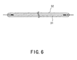
- the ultraviolet ray light source 3 may be an ultraviolet ray fluorescent lamp, which is provided with a discharge vessel 31 accommodated in an outer bulb 32 together with rare gas, e.g., xenon, at about 1.3Pa. Moreover, the pressure of the rare gas filling the outer bulb 32 may be atmospheric pressure or less to avoid changing the condition in the discharge vessel. As a result, thermal conductivity between the outer bulb 32 and the discharge vessel 31 lowers, so that the temperature of the discharge vessel is maintained. Accordingly, the lamp can appropriately radiate ultraviolet rays, even if the photocatalytic beads 4 contact the surface of the outer bulb 32.
- rare gas e.g., xenon
- the fluorescent lamp has preferred dimensions as follows. Whole lamp length 80 mm Outer diameter of the discharge vessel 1.6 mm Outer diameter of the outer bulb 2.2 mm The rated lamp power 0.5 W
- the discharge vessel 31 is filled with a gas, including, for example, mercury (Hg), and rare gas, e.g., argon, krypton or xenon, and a pair of cold cathodes connected to a high frequency inverter circuit 33.
- a gas including, for example, mercury (Hg), and rare gas, e.g., argon, krypton or xenon, and a pair of cold cathodes connected to a high frequency inverter circuit 33.
- a phosphor layer is coated on the inner surface of the discharge vessel 31.
- the layer converts ultraviolet radiation of 254 nm generated by the discharge into visible light and ultraviolet radiation within 300 nm to 400 nm.
- the layer has a luminescent compound, which generates the ultraviolet radiation, is strontium boron oxide activated by europium, e.g., indicated as SrB 4 O 7 : Eu 2+ , which has a peak emission at 368 nm.
- alkaline earth metal silicate activated by lead e.g., indicated as follows (Ba, Sr, Mg) 3 Si 2 O 7 : Pb 2+ or BaSi 2 O 5 : Pb 2+
- alkaline earth metal phosphate activated by europium e.g., indicated as (SrMg) 2 P 2 O 7 : Eu 2+
- rare earth metal phosphate activated by cerium e.g., indicated as YPO 4 : Ce 2+
- the ultraviolet radiation within 300 nm to 400 nm is useful for the photocatalyst activating.
- a low-pressure mercury vapor discharge lamp 3 like a fluorescent lamp, a rare gas discharge lamp, or a halogen incandescent lamp may provide the ultraviolet ray light source 3.
- the fluorescent lamp 3 is located in the center of the enclosure 1, and both sides of the lamp 3 are respectively fixed to the side plates lb, lb' via an insulator, e.g., a rubber or silicone.
- the photocatalytic beads 4 fill the enclosure 1.
- the beads are comprised a spherical body made of silica gel and a photocatalyst layer made of titanium oxide.
- the photocatalytic beads are preferably manufactured by coating titania sol on the silica gel and drying it.
- the titanium oxide can be manufactured by other methods such as dipping or spraying titanium oxide on the spherical body, or stacking particles made of titanium oxide on the spherical body.
- the average diameter of the particles may be more than nano-meter orders, preferably within 50 nm to 3000 nm.
- the spherical bodies or the photocatalytic beads may not be accurately spherical shape. That is, the bodies or the photocatalytic beads have any shape that does not flaw the outer surface of the fluorescent lamp at a contact surface.
- the spherical body is preferably made of glass or ceramic, which has higher ultraviolet radiation transmittance.
- silica gel can also absorb moisture, the silica gel containing moisture effectively promotes the photocatalysis.
- FIG.3 is a graph showing a relationship between a quantity of photocatalytic beads and a diameter of the photocatalytic beads as shown in FIG.1.
- the graph has two peaks at about 3 mm and 4 mm.
- these photocatalytic beads 4 can effectively remove the odor ingredients, because the surface area of the photocatalyst in the enclosure 1 becomes large and also many airflow passages are formed.
- these photocatalytic beads 4 are filled in the enclosure as shown FIG.2, so that many airflow passages are formed through the photocatalytic beads 4 in the enclosure 1. Accordingly, the air can flow from the primary element through the airflow passages to the photocatalytic beads 4.
- the above-mentioned photocatalyst is a substance that can convert photo energy into chemical energy.
- the particles of the metallic oxide constituting the photocatalyst are semiconducting.
- the semiconductor has a charge band, a conduction band and a band gap therebetween.
- the band gap has a value of eV inherent to the photocatalyst.
- the photocatalyst comprises titanium oxide a sort of semiconductor
- its band gap is 3 eV.
- light having a wavelength shorter than about 413 nm is applied onto the titanium oxide, electrons in the charge band jump to the conduction band.
- the electrons create positive holes h + where the electrons e - left. This condition corresponds to an excited condition of the photocatalyst.
- the excited condition is created, when the ultraviolet radiation is applied onto the titanium oxide.
- OH-radical is created around the surface of the photocatalyst, while a hydroxyl group OH reacts on the h + .
- the OH - is decomposed from water content H 2 O around the photocatalyst. This OH-radical acts to oxidize and decompose the odor ingredients.
- the substance of photocatalyst may be one or more selected from a group of titanium oxide (TiO 2 ) of anatase structure, zinc oxide (ZnO), tungsten oxide (WO 3 ), iron oxide (Fe 2 O 3 ), lanthanum rhodium phosphorus (LaRhP 3 ), iron titanium oxide (FeTiO 3 ), cadmium diiron oxide (CdFe 2 O 4 ) and strontium titanium oxide (SrTiO 3 ).
- titanium oxide or zinc oxide itself may form the photocatalytic beads by means of the known vapor-phase epitaxy method or the cohesive method.
- the beads comprise the particles of titanium oxide or zinc oxide, ultraviolet radiation can transmit through the particles. Accordingly, photocatalysis occurs even in the particles.
- the odor removing apparatus 10 is disposed along airflow passages, which contain odor producing ingredients such as acetaldehyde.
- the air flows into the photocatalytic beads 4 through one primary element of the enclosure 1, and is exhausted from another primary element.
- the ultraviolet radiation within 300 nm to 400 nm from the lamp is applied on the photocatalytic beads 4, while ultraviolet radiation passes the airflow passages with reflection or diffusion.
- This condition corresponds to an excited condition of the photocatalyst.
- the excited condition is created, when the ultraviolet radiation is applied onto the titanium oxide.
- An OH-radical is generated around the photocatalyst. This OH-radical acts to oxidize and decompose the above-mentioned odor ingredients, e.g., acetaldehyde (CH 3 CHO). This oxidation and decomposition occur according to the following chemical formula to eliminate any bad smell.
- CH 3 CHO + OH-radical ⁇ CH 3 C + H 2 O + CO 2
- Any other odor producing ingredients can also be decomposed oxidation forces of the OH-radical to eliminate the bad smell.
- FIG.4 is a graph showing a relationship between concentration of acetaldehyde gas and operational time of the apparatus.
- the horizontal axis indicates an operational time of the apparatus.
- the vertical axis indicates a respective concentration of acetaldehyde gas.
- the Example line (a) designates the relative concentration of acetaldehyde gas referenced to the comparative example line (b).
- the apparatus uses a fluorescent lamp without an outer bulb.
- the apparatus of the embodiment is disposed in a room having an interior volume of 500 liters.
- the room is filled with air including acetaldehyde.
- a blower fan in the room introduces acetaldehyde gas into the apparatus.
- the temperature is approximately minus ten degrees centigrade.
- a gas chromatography is used for operating a quantitative analysis of acetaldehyde gas in every constant time. It is seen that the relative concentration of the example is better than that of the comparative example In the low temperature environment. Because the example can prevent reducing energy of ultraviolet radiation relatively. That is, the outer bulb 32 can maintain a constant mercury vapor pressure of the fluorescent lamp 3, because the outer bulb 32 can prevent dissipation of the heat from the discharge vessel 31.
- FIG. 5 shows a cross section of the refrigerating apparatus 50. It is provided with a refrigerating room 52, a freezer 51 above the refrigerating room, an airflow passage to communicate them, the odor removing apparatus 10 to be detachably mounted in the airflow passage, a blower fan 54 and an air compressor (not shown). Alternatively, the odor removing apparatus may be disposed in the refrigerating room.
- the refrigerating room is separated from the freezer by a partition having another passage allowing airflow.
- the former passage is disposed at the back of the refrigerating room 52 and the freezer 51, and connects them. Accordingly, the airflow caused by the blower fan 54 circulates in the refrigerating apparatus as shown by arrows in FIG.5.
- the photocatalytic beads 4 of the odor removing apparatus 10 decompose the odor ingredients.
- the ultraviolet radiation within 300 nm to 400 nm from fluorescent lamp 3 of the odor removing apparatus 10 is applied on the photocatalytic beads 4, the excited condition of the photocatalyst is created. Accordingly, as mentioned above, OH-radicals act to oxidize and decompose odor ingredients in the airflow.
- the fluorescent lamp may light on always, or be controlled by a timer or something to synchronize it. That is, the lamp may be lit, when a door of the refrigerating apparatus opens or shuts. Further, when the compressor or the blow fan operates or stops, the fluorescent lamp may turn on.
- the airflow and the fluorescent lamp become cold.
- the progress of evaporation of mercury (Hg) in a fluorescent lamp is decreased, so that the lamp reduces energy of the ultraviolet radiation.
- the fluorescent lamp of this embodiment can prevent lowering the progress of the evaporation. Because the outer bulb 32 of the fluorescent lamp can prevent dissipation of the heat from the discharge vessel 31. Accordingly, the fluorescent lamp can respectively maintain the temperature of the discharge vessel 31 and Hg-vapor pressure thereof. Consequently, even if the odor removing apparatus is used at such a low temperature, the excited condition of the photocatalyst is constantly created. Therefore, the odor removing apparatus can effectively oxidize and decompose the odor ingredients.
- the oder removing apparatus may be used in an air conditioner or any other apparatus having flowing air.
Landscapes
- Health & Medical Sciences (AREA)
- General Health & Medical Sciences (AREA)
- Chemical Kinetics & Catalysis (AREA)
- Epidemiology (AREA)
- Life Sciences & Earth Sciences (AREA)
- Animal Behavior & Ethology (AREA)
- Chemical & Material Sciences (AREA)
- Public Health (AREA)
- Veterinary Medicine (AREA)
- Disinfection, Sterilisation Or Deodorisation Of Air (AREA)
- Exhaust Gas Treatment By Means Of Catalyst (AREA)
- Catalysts (AREA)
- Cold Air Circulating Systems And Constructional Details In Refrigerators (AREA)
Abstract
Description
| | 80 mm |
| Outer diameter of the discharge vessel | 1.6 mm |
| Outer diameter of the outer bulb | 2.2 mm |
| The rated lamp power | 0.5 W |
According to the refrigerating apparatus, since the ultraviolet radiation within 300 nm to 400 nm from
Claims (10)
- An odor removing apparatus comprising:an ultraviolet ray light source (3) for radiating ultraviolet rays;an enclosure (1) holding said light source (3) and a photocatalytic substance (4), wherein air passes through said enclosure;said odor removing apparatus being characterized in that said photocatalytic substance (4) comprises a plurality of photocatalytic beads (4) arranged to receive the ultraviolet rays from said light source (3).
- An odor removing apparatus according to claim 1, wherein said photocatalytic beads (4) contact said light source (3).
- An odor removing apparatus according to claim 1, wherein said photocatalytic beads (4) comprise a spherical body made of either glass or silica gel and a photocatalyst comprises titanium oxide, or zinc oxide, coated on the body.
- An odor removing apparatus according to claim 1, wherein said photocatalytic beads (4) comprise titanium oxide, or zinc oxide.
- An odor removing apparatus according to claim 1, wherein each photocatalytic bead (4) has a different diameter causing plural peaks of distribution.
- An odor removing apparatus according to claim 1, wherein said enclosure (1) defines holes (2); and wherein said photocatalytic beads (4) are not able to pass through said holes (2).
- An odor removing apparatus comprising:an ultraviolet ray discharge lamp (3) for radiating ultraviolet rays;a photocatalytic substance (4) arranged to receive ultrav iolet rays from said discharge lamp (3);an enclosure (1) holding said discharge lamp (3) and said photocatalytic substance (4), wherein air passes through said enclosure (1);said odor removing apparatus being characterized in that said ultraviolet ray discharge lamp (3) has an outer bulb (32) filled with gas at pressure less than or equal to atmospheric pressure and a discharge vessel (31) containing mercury (Hg), and a rare gas, said discharge vessel (31) being in said outer bulb (32) along an axis thereof.
- An odor removing apparatus according to said claim 7, wherein said photocatalytic substance (4) comprises photocatalytic beads; and wherein
said photocatalytic beads (4) contact said outer bulb (32) of said ultraviolet ray discharge lamp (3). - A refrigerating apparatus, comprising:
an odor removing apparatus (1), comprising:an ultraviolet ray light source (3) for radiating ultraviolet rays,a photocatalytic substance (4), andan enclosure (1) holding said light source (3) and said photocatalytic substance(4);an airflow passage through said odor removing apparatus (10); anda refrigerating housing accommodating said odor removing apparatus (10) and said airflow passage;said refrigerating apparatus being characterized in that said photocatalytic substance (4) comprises a plurality of photocatalytic beads (4) arranged to receive the ultraviolet rays from said light source (3). - A refrigerating apparatus comprising:an odor removing apparatus (10) comprising:an ultraviolet ray discharge lamp (3) for radiating ultraviolet rays,a photocatalytic substance (4) arranged to receive ultraviolet rays from said discharge lamp (3),an enclosure (1) holding said discharge lamp (3) and said photocatalytic substance (4), wherein air passes through said enclosure (1);an airflow passage through said odor removing apparatus (10); anda refrigerating housing accommodating said odor removing apparatus (10) and said airflow passage;said refrigerating apparatus being characterized in that said ultraviolet ray discharge lamp (3) has an outer bulb (32) filled with gas at pressure less than or equal to atmospheric pressure and a discharge vessel (31) containing mercury (Hg), and a rare gas, said discharge vessel (31) being in said outer bulb (32) along an axis thereof.
Applications Claiming Priority (2)
| Application Number | Priority Date | Filing Date | Title |
|---|---|---|---|
| JP37575899A JP2001187124A (en) | 1999-12-28 | 1999-12-28 | Deodorizer and refrigerator |
| JP37575899 | 1999-12-28 |
Publications (2)
| Publication Number | Publication Date |
|---|---|
| EP1112752A2 true EP1112752A2 (en) | 2001-07-04 |
| EP1112752A3 EP1112752A3 (en) | 2001-09-19 |
Family
ID=18506016
Family Applications (1)
| Application Number | Title | Priority Date | Filing Date |
|---|---|---|---|
| EP00311457A Withdrawn EP1112752A3 (en) | 1999-12-28 | 2000-12-20 | An odor removing apparatus and a refrigerating apparatus using the same |
Country Status (3)
| Country | Link |
|---|---|
| US (1) | US20010052237A1 (en) |
| EP (1) | EP1112752A3 (en) |
| JP (1) | JP2001187124A (en) |
Cited By (11)
| Publication number | Priority date | Publication date | Assignee | Title |
|---|---|---|---|---|
| WO2003033037A1 (en) * | 2001-10-16 | 2003-04-24 | Nichimen Chemical Industry Co., Ltd. | Deodorizing device |
| WO2004110509A1 (en) * | 2003-05-30 | 2004-12-23 | Carrier Corporation | Air purification system using ultra-violet photocatalytic oxidation |
| WO2007072165A3 (en) * | 2005-12-19 | 2008-01-03 | Indesit Co Spa | Apparatus adapted to store and/or preserve foodstuffs comprising an inner compartment |
| US7399331B2 (en) | 2003-05-29 | 2008-07-15 | Carrier Corporation | Gas phase contaminant removal with low pressure drop |
| EP1732616A4 (en) * | 2004-03-31 | 2008-12-03 | Univ Florida | SYSTEMS AND METHODS FOR REVITALIZING AIR |
| EP1574225A4 (en) * | 2002-11-15 | 2009-05-06 | Fujitsu Ltd | AIR CLEANER |
| CN101962538A (en) * | 2009-09-29 | 2011-02-02 | 鹤壁佳多科工贸有限责任公司 | Lead-excited barium silicate ultraviolet fluorescent powder |
| EP2361639A3 (en) * | 2007-03-27 | 2012-01-18 | John J. Hayman Jr. | Photocatalytic air treatment system and method |
| WO2018074864A1 (en) * | 2016-10-19 | 2018-04-26 | Samsung Electronics Co., Ltd. | Photocatalyst filter and air conditioner including the same |
| CN109844411A (en) * | 2016-10-19 | 2019-06-04 | 三星电子株式会社 | Photocatalytic filter and air-conditioning including the photocatalytic filter |
| CN111457498A (en) * | 2020-04-09 | 2020-07-28 | 常州科镭光电有限公司 | Ultraviolet photocatalyst air purification box |
Families Citing this family (10)
| Publication number | Priority date | Publication date | Assignee | Title |
|---|---|---|---|---|
| US7988923B2 (en) * | 2004-02-23 | 2011-08-02 | Rgf Environmental Group, Inc. | Device, system and method for an advanced oxidation process using photohydroionization |
| JP2005279534A (en) * | 2004-03-30 | 2005-10-13 | Okaya Electric Ind Co Ltd | Photocatalyst carrying body |
| US20090007582A1 (en) * | 2007-07-05 | 2009-01-08 | Ulanov Gennady N | Air conditioning system |
| JP2010046604A (en) * | 2008-08-21 | 2010-03-04 | Utsunomiya Univ | Photocatalyst, method for producing hydrogen and method for decomposing organic matter |
| EP2525173B1 (en) * | 2011-05-18 | 2018-11-21 | Whirlpool Corporation | Fruits and vegetables compartment of a refrigerator with means for preserving freshness |
| JP6778343B1 (en) * | 2020-02-13 | 2020-10-28 | 倫文 木原 | UV cut filter |
| JP7446962B2 (en) * | 2020-09-21 | 2024-03-11 | 倫文 木原 | UV cut filter |
| CN112473366B (en) * | 2020-12-11 | 2023-01-06 | 赋舜材料科技有限公司 | A photocatalyst air purification device |
| KR102351680B1 (en) * | 2021-03-12 | 2022-01-14 | 위아비 주식회사 | Photocatalysts filter module |
| KR102483776B1 (en) * | 2022-01-05 | 2023-01-03 | 주식회사 첨단랩 | Air purification device with modular structure |
Family Cites Families (10)
| Publication number | Priority date | Publication date | Assignee | Title |
|---|---|---|---|---|
| DE69433980T2 (en) * | 1993-10-26 | 2005-09-01 | E. Heller & Co., Oakland | PHOTO CATALYST AND BINDER CONTAINING COMPOSITIONS |
| JP2885638B2 (en) * | 1994-03-28 | 1999-04-26 | 株式会社東芝 | refrigerator |
| JPH09234376A (en) * | 1996-03-04 | 1997-09-09 | Tao:Kk | Molded product with photocatalytic function |
| JPH09313581A (en) * | 1996-06-03 | 1997-12-09 | Nippon Muki Co Ltd | Deodorizing method and deodorizing device for refrigerator |
| JPH10154488A (en) * | 1996-06-27 | 1998-06-09 | Toshiba Lighting & Technol Corp | Fluorescent lamp for photocatalyst and cleaning device |
| JPH1015393A (en) * | 1996-07-08 | 1998-01-20 | Fumihide Shiraishi | Photocatalytic reactor |
| CN1089541C (en) * | 1996-10-31 | 2002-08-21 | 东芝照明技术株式会社 | Low-voltage mercury vapour discharge lamp, illuminating apparatus and display device |
| JPH10235202A (en) * | 1997-02-28 | 1998-09-08 | Toshiba Lighting & Technol Corp | Photocatalyst and air purifier |
| JPH11114045A (en) * | 1997-10-09 | 1999-04-27 | Nhk Spring Co Ltd | Deodorizing device |
| JP3573933B2 (en) * | 1997-11-12 | 2004-10-06 | 株式会社ティ・アンド・シー・テクニカル | UV oxidation equipment |
-
1999
- 1999-12-28 JP JP37575899A patent/JP2001187124A/en active Pending
-
2000
- 2000-12-20 EP EP00311457A patent/EP1112752A3/en not_active Withdrawn
- 2000-12-28 US US09/749,739 patent/US20010052237A1/en not_active Abandoned
Cited By (15)
| Publication number | Priority date | Publication date | Assignee | Title |
|---|---|---|---|---|
| WO2003033037A1 (en) * | 2001-10-16 | 2003-04-24 | Nichimen Chemical Industry Co., Ltd. | Deodorizing device |
| EP1574225A4 (en) * | 2002-11-15 | 2009-05-06 | Fujitsu Ltd | AIR CLEANER |
| US8080214B2 (en) | 2002-11-15 | 2011-12-20 | Fujitsu Limited | Air cleaner |
| US7399331B2 (en) | 2003-05-29 | 2008-07-15 | Carrier Corporation | Gas phase contaminant removal with low pressure drop |
| WO2004110509A1 (en) * | 2003-05-30 | 2004-12-23 | Carrier Corporation | Air purification system using ultra-violet photocatalytic oxidation |
| EP1732616A4 (en) * | 2004-03-31 | 2008-12-03 | Univ Florida | SYSTEMS AND METHODS FOR REVITALIZING AIR |
| WO2007072165A3 (en) * | 2005-12-19 | 2008-01-03 | Indesit Co Spa | Apparatus adapted to store and/or preserve foodstuffs comprising an inner compartment |
| EP2361639A3 (en) * | 2007-03-27 | 2012-01-18 | John J. Hayman Jr. | Photocatalytic air treatment system and method |
| CN101962538A (en) * | 2009-09-29 | 2011-02-02 | 鹤壁佳多科工贸有限责任公司 | Lead-excited barium silicate ultraviolet fluorescent powder |
| WO2018074864A1 (en) * | 2016-10-19 | 2018-04-26 | Samsung Electronics Co., Ltd. | Photocatalyst filter and air conditioner including the same |
| CN109844411A (en) * | 2016-10-19 | 2019-06-04 | 三星电子株式会社 | Photocatalytic filter and air-conditioning including the photocatalytic filter |
| EP3488155A4 (en) * | 2016-10-19 | 2019-12-11 | Samsung Electronics Co., Ltd. | PHOTOCATALYST FILTER AND AIR CONDITIONER COMPRISING THE SAME |
| US10722605B2 (en) | 2016-10-19 | 2020-07-28 | Samsung Electronics Co., Ltd. | Photocatalyst filter and air conditioner including the same |
| US11701446B2 (en) | 2016-10-19 | 2023-07-18 | Samsung Electronics Co., Ltd. | Photocatalyst filter and air conditioner including the same |
| CN111457498A (en) * | 2020-04-09 | 2020-07-28 | 常州科镭光电有限公司 | Ultraviolet photocatalyst air purification box |
Also Published As
| Publication number | Publication date |
|---|---|
| JP2001187124A (en) | 2001-07-10 |
| US20010052237A1 (en) | 2001-12-20 |
| EP1112752A3 (en) | 2001-09-19 |
Similar Documents
| Publication | Publication Date | Title |
|---|---|---|
| US20010052237A1 (en) | Order removing apparatus and a refrigerating apparatus using the order removing apparatus | |
| US5801483A (en) | Fluorescent lamp having visible and UV radiation | |
| JP3573392B2 (en) | Photocatalyst, light source and lighting equipment | |
| JP2001332216A (en) | Discharge lamp, light irradiation device, sterilization device, liquid treatment device and air cleaning device | |
| JP2002204653A (en) | Gas removal equipment | |
| JP2001081460A (en) | Ultraviolet light emitting material, ultraviolet light emitting fluorescent lamp and ultraviolet light emitting device using the same | |
| EP1403906B1 (en) | Discharge lamp and ultraviolet irradiation system and operation method therefor | |
| US20030076028A1 (en) | Method of activating photocatalysis, photocatalytic discharge tube, and device using the same | |
| JP2001172624A (en) | Ultraviolet light emitting material, ultraviolet light emitting fluorescent lamp and ultraviolet light emitting device using the same | |
| JP4459022B2 (en) | Cleaning device | |
| JP2003190812A (en) | Photocatalyst | |
| JPH09129012A (en) | Photocatalysts, fluorescent lamps and lighting fixtures | |
| JP2001155690A (en) | Photocatalytic mechanism, photocatalytic deodorizer, and device with photocatalytic deodorizing function | |
| JP3551279B2 (en) | Article with photocatalyst device for low temperature and article with lighting device for low temperature | |
| JPH09262483A (en) | Photocatalysts and lamps and lighting fixtures | |
| JPH10235202A (en) | Photocatalyst and air purifier | |
| JP3772388B2 (en) | Photocatalyst, incandescent bulb, discharge lamp and lighting fixture | |
| JP4662778B2 (en) | Electric and fluorescent lights | |
| JPH0992225A (en) | Dielectric barrier discharge lamp | |
| JPH10154488A (en) | Fluorescent lamp for photocatalyst and cleaning device | |
| JP3688869B2 (en) | Purifier in refrigerator | |
| JP3396993B2 (en) | Fluorescent lamps and lighting equipment | |
| JPH0684498A (en) | Low pressure mercury vapor discharge lamp for UV irradiation | |
| JP2001015068A (en) | UV fluorescent lamp | |
| EP1323181B1 (en) | Very high output low pressure discharge lamp |
Legal Events
| Date | Code | Title | Description |
|---|---|---|---|
| PUAI | Public reference made under article 153(3) epc to a published international application that has entered the european phase |
Free format text: ORIGINAL CODE: 0009012 |
|
| AK | Designated contracting states |
Kind code of ref document: A2 Designated state(s): AT BE CH CY DE DK ES FI FR GB GR IE IT LI LU MC NL PT SE TR |
|
| AX | Request for extension of the european patent |
Free format text: AL;LT;LV;MK;RO;SI |
|
| PUAL | Search report despatched |
Free format text: ORIGINAL CODE: 0009013 |
|
| RIC1 | Information provided on ipc code assigned before grant |
Free format text: 7A 61L 9/20 A, 7H 01J 61/34 B, 7H 01J 61/72 B, 7H 01J 61/20 B |
|
| AK | Designated contracting states |
Kind code of ref document: A3 Designated state(s): AT BE CH CY DE DK ES FI FR GB GR IE IT LI LU MC NL PT SE TR |
|
| AX | Request for extension of the european patent |
Free format text: AL;LT;LV;MK;RO;SI |
|
| AKX | Designation fees paid | ||
| REG | Reference to a national code |
Ref country code: DE Ref legal event code: 8566 |
|
| STAA | Information on the status of an ep patent application or granted ep patent |
Free format text: STATUS: THE APPLICATION IS DEEMED TO BE WITHDRAWN |
|
| 18D | Application deemed to be withdrawn |
Effective date: 20020320 |