EP1111662B1 - Method for aligning semiconductor die to interconnect metal on flex substrate - Google Patents
Method for aligning semiconductor die to interconnect metal on flex substrate Download PDFInfo
- Publication number
- EP1111662B1 EP1111662B1 EP00311553A EP00311553A EP1111662B1 EP 1111662 B1 EP1111662 B1 EP 1111662B1 EP 00311553 A EP00311553 A EP 00311553A EP 00311553 A EP00311553 A EP 00311553A EP 1111662 B1 EP1111662 B1 EP 1111662B1
- Authority
- EP
- European Patent Office
- Prior art keywords
- die
- looking camera
- bond pads
- fiducials
- downward
- Prior art date
- Legal status (The legal status is an assumption and is not a legal conclusion. Google has not performed a legal analysis and makes no representation as to the accuracy of the status listed.)
- Expired - Lifetime
Links
Images

Classifications
-
- H—ELECTRICITY
- H01—ELECTRIC ELEMENTS
- H01L—SEMICONDUCTOR DEVICES NOT COVERED BY CLASS H10
- H01L24/00—Arrangements for connecting or disconnecting semiconductor or solid-state bodies; Methods or apparatus related thereto
- H01L24/74—Apparatus for manufacturing arrangements for connecting or disconnecting semiconductor or solid-state bodies
- H01L24/76—Apparatus for connecting with build-up interconnects
-
- H—ELECTRICITY
- H01—ELECTRIC ELEMENTS
- H01L—SEMICONDUCTOR DEVICES NOT COVERED BY CLASS H10
- H01L23/00—Details of semiconductor or other solid state devices
- H01L23/52—Arrangements for conducting electric current within the device in operation from one component to another, i.e. interconnections, e.g. wires, lead frames
- H01L23/538—Arrangements for conducting electric current within the device in operation from one component to another, i.e. interconnections, e.g. wires, lead frames the interconnection structure between a plurality of semiconductor chips being formed on, or in, insulating substrates
- H01L23/5389—Arrangements for conducting electric current within the device in operation from one component to another, i.e. interconnections, e.g. wires, lead frames the interconnection structure between a plurality of semiconductor chips being formed on, or in, insulating substrates the chips being integrally enclosed by the interconnect and support structures
-
- H—ELECTRICITY
- H01—ELECTRIC ELEMENTS
- H01L—SEMICONDUCTOR DEVICES NOT COVERED BY CLASS H10
- H01L24/00—Arrangements for connecting or disconnecting semiconductor or solid-state bodies; Methods or apparatus related thereto
- H01L24/01—Means for bonding being attached to, or being formed on, the surface to be connected, e.g. chip-to-package, die-attach, "first-level" interconnects; Manufacturing methods related thereto
- H01L24/18—High density interconnect [HDI] connectors; Manufacturing methods related thereto
- H01L24/19—Manufacturing methods of high density interconnect preforms
-
- H—ELECTRICITY
- H01—ELECTRIC ELEMENTS
- H01L—SEMICONDUCTOR DEVICES NOT COVERED BY CLASS H10
- H01L24/00—Arrangements for connecting or disconnecting semiconductor or solid-state bodies; Methods or apparatus related thereto
- H01L24/80—Methods for connecting semiconductor or other solid state bodies using means for bonding being attached to, or being formed on, the surface to be connected
- H01L24/82—Methods for connecting semiconductor or other solid state bodies using means for bonding being attached to, or being formed on, the surface to be connected by forming build-up interconnects at chip-level, e.g. for high density interconnects [HDI]
-
- H—ELECTRICITY
- H01—ELECTRIC ELEMENTS
- H01L—SEMICONDUCTOR DEVICES NOT COVERED BY CLASS H10
- H01L2223/00—Details relating to semiconductor or other solid state devices covered by the group H01L23/00
- H01L2223/544—Marks applied to semiconductor devices or parts
- H01L2223/54426—Marks applied to semiconductor devices or parts for alignment
-
- H—ELECTRICITY
- H01—ELECTRIC ELEMENTS
- H01L—SEMICONDUCTOR DEVICES NOT COVERED BY CLASS H10
- H01L2224/00—Indexing scheme for arrangements for connecting or disconnecting semiconductor or solid-state bodies and methods related thereto as covered by H01L24/00
- H01L2224/01—Means for bonding being attached to, or being formed on, the surface to be connected, e.g. chip-to-package, die-attach, "first-level" interconnects; Manufacturing methods related thereto
- H01L2224/02—Bonding areas; Manufacturing methods related thereto
- H01L2224/04—Structure, shape, material or disposition of the bonding areas prior to the connecting process
- H01L2224/04105—Bonding areas formed on an encapsulation of the semiconductor or solid-state body, e.g. bonding areas on chip-scale packages
-
- H—ELECTRICITY
- H01—ELECTRIC ELEMENTS
- H01L—SEMICONDUCTOR DEVICES NOT COVERED BY CLASS H10
- H01L2224/00—Indexing scheme for arrangements for connecting or disconnecting semiconductor or solid-state bodies and methods related thereto as covered by H01L24/00
- H01L2224/01—Means for bonding being attached to, or being formed on, the surface to be connected, e.g. chip-to-package, die-attach, "first-level" interconnects; Manufacturing methods related thereto
- H01L2224/26—Layer connectors, e.g. plate connectors, solder or adhesive layers; Manufacturing methods related thereto
- H01L2224/31—Structure, shape, material or disposition of the layer connectors after the connecting process
- H01L2224/32—Structure, shape, material or disposition of the layer connectors after the connecting process of an individual layer connector
- H01L2224/321—Disposition
- H01L2224/32151—Disposition the layer connector connecting between a semiconductor or solid-state body and an item not being a semiconductor or solid-state body, e.g. chip-to-substrate, chip-to-passive
- H01L2224/32221—Disposition the layer connector connecting between a semiconductor or solid-state body and an item not being a semiconductor or solid-state body, e.g. chip-to-substrate, chip-to-passive the body and the item being stacked
- H01L2224/32225—Disposition the layer connector connecting between a semiconductor or solid-state body and an item not being a semiconductor or solid-state body, e.g. chip-to-substrate, chip-to-passive the body and the item being stacked the item being non-metallic, e.g. insulating substrate with or without metallisation
-
- H—ELECTRICITY
- H01—ELECTRIC ELEMENTS
- H01L—SEMICONDUCTOR DEVICES NOT COVERED BY CLASS H10
- H01L2224/00—Indexing scheme for arrangements for connecting or disconnecting semiconductor or solid-state bodies and methods related thereto as covered by H01L24/00
- H01L2224/80—Methods for connecting semiconductor or other solid state bodies using means for bonding being attached to, or being formed on, the surface to be connected
- H01L2224/83—Methods for connecting semiconductor or other solid state bodies using means for bonding being attached to, or being formed on, the surface to be connected using a layer connector
- H01L2224/8312—Aligning
- H01L2224/83136—Aligning involving guiding structures, e.g. spacers or supporting members
- H01L2224/83138—Aligning involving guiding structures, e.g. spacers or supporting members the guiding structures being at least partially left in the finished device
- H01L2224/8314—Guiding structures outside the body
-
- H—ELECTRICITY
- H01—ELECTRIC ELEMENTS
- H01L—SEMICONDUCTOR DEVICES NOT COVERED BY CLASS H10
- H01L2224/00—Indexing scheme for arrangements for connecting or disconnecting semiconductor or solid-state bodies and methods related thereto as covered by H01L24/00
- H01L2224/80—Methods for connecting semiconductor or other solid state bodies using means for bonding being attached to, or being formed on, the surface to be connected
- H01L2224/83—Methods for connecting semiconductor or other solid state bodies using means for bonding being attached to, or being formed on, the surface to be connected using a layer connector
- H01L2224/8319—Arrangement of the layer connectors prior to mounting
- H01L2224/83192—Arrangement of the layer connectors prior to mounting wherein the layer connectors are disposed only on another item or body to be connected to the semiconductor or solid-state body
-
- H—ELECTRICITY
- H01—ELECTRIC ELEMENTS
- H01L—SEMICONDUCTOR DEVICES NOT COVERED BY CLASS H10
- H01L2224/00—Indexing scheme for arrangements for connecting or disconnecting semiconductor or solid-state bodies and methods related thereto as covered by H01L24/00
- H01L2224/91—Methods for connecting semiconductor or solid state bodies including different methods provided for in two or more of groups H01L2224/80 - H01L2224/90
- H01L2224/92—Specific sequence of method steps
- H01L2224/921—Connecting a surface with connectors of different types
- H01L2224/9212—Sequential connecting processes
- H01L2224/92142—Sequential connecting processes the first connecting process involving a layer connector
- H01L2224/92144—Sequential connecting processes the first connecting process involving a layer connector the second connecting process involving a build-up interconnect
-
- H—ELECTRICITY
- H01—ELECTRIC ELEMENTS
- H01L—SEMICONDUCTOR DEVICES NOT COVERED BY CLASS H10
- H01L2924/00—Indexing scheme for arrangements or methods for connecting or disconnecting semiconductor or solid-state bodies as covered by H01L24/00
- H01L2924/01—Chemical elements
- H01L2924/01004—Beryllium [Be]
-
- H—ELECTRICITY
- H01—ELECTRIC ELEMENTS
- H01L—SEMICONDUCTOR DEVICES NOT COVERED BY CLASS H10
- H01L2924/00—Indexing scheme for arrangements or methods for connecting or disconnecting semiconductor or solid-state bodies as covered by H01L24/00
- H01L2924/01—Chemical elements
- H01L2924/01005—Boron [B]
-
- H—ELECTRICITY
- H01—ELECTRIC ELEMENTS
- H01L—SEMICONDUCTOR DEVICES NOT COVERED BY CLASS H10
- H01L2924/00—Indexing scheme for arrangements or methods for connecting or disconnecting semiconductor or solid-state bodies as covered by H01L24/00
- H01L2924/01—Chemical elements
- H01L2924/01006—Carbon [C]
-
- H—ELECTRICITY
- H01—ELECTRIC ELEMENTS
- H01L—SEMICONDUCTOR DEVICES NOT COVERED BY CLASS H10
- H01L2924/00—Indexing scheme for arrangements or methods for connecting or disconnecting semiconductor or solid-state bodies as covered by H01L24/00
- H01L2924/01—Chemical elements
- H01L2924/01013—Aluminum [Al]
-
- H—ELECTRICITY
- H01—ELECTRIC ELEMENTS
- H01L—SEMICONDUCTOR DEVICES NOT COVERED BY CLASS H10
- H01L2924/00—Indexing scheme for arrangements or methods for connecting or disconnecting semiconductor or solid-state bodies as covered by H01L24/00
- H01L2924/01—Chemical elements
- H01L2924/01018—Argon [Ar]
-
- H—ELECTRICITY
- H01—ELECTRIC ELEMENTS
- H01L—SEMICONDUCTOR DEVICES NOT COVERED BY CLASS H10
- H01L2924/00—Indexing scheme for arrangements or methods for connecting or disconnecting semiconductor or solid-state bodies as covered by H01L24/00
- H01L2924/01—Chemical elements
- H01L2924/01027—Cobalt [Co]
-
- H—ELECTRICITY
- H01—ELECTRIC ELEMENTS
- H01L—SEMICONDUCTOR DEVICES NOT COVERED BY CLASS H10
- H01L2924/00—Indexing scheme for arrangements or methods for connecting or disconnecting semiconductor or solid-state bodies as covered by H01L24/00
- H01L2924/01—Chemical elements
- H01L2924/01029—Copper [Cu]
-
- H—ELECTRICITY
- H01—ELECTRIC ELEMENTS
- H01L—SEMICONDUCTOR DEVICES NOT COVERED BY CLASS H10
- H01L2924/00—Indexing scheme for arrangements or methods for connecting or disconnecting semiconductor or solid-state bodies as covered by H01L24/00
- H01L2924/01—Chemical elements
- H01L2924/01033—Arsenic [As]
-
- H—ELECTRICITY
- H01—ELECTRIC ELEMENTS
- H01L—SEMICONDUCTOR DEVICES NOT COVERED BY CLASS H10
- H01L2924/00—Indexing scheme for arrangements or methods for connecting or disconnecting semiconductor or solid-state bodies as covered by H01L24/00
- H01L2924/01—Chemical elements
- H01L2924/01039—Yttrium [Y]
-
- H—ELECTRICITY
- H01—ELECTRIC ELEMENTS
- H01L—SEMICONDUCTOR DEVICES NOT COVERED BY CLASS H10
- H01L2924/00—Indexing scheme for arrangements or methods for connecting or disconnecting semiconductor or solid-state bodies as covered by H01L24/00
- H01L2924/01—Chemical elements
- H01L2924/01074—Tungsten [W]
-
- H—ELECTRICITY
- H01—ELECTRIC ELEMENTS
- H01L—SEMICONDUCTOR DEVICES NOT COVERED BY CLASS H10
- H01L2924/00—Indexing scheme for arrangements or methods for connecting or disconnecting semiconductor or solid-state bodies as covered by H01L24/00
- H01L2924/01—Chemical elements
- H01L2924/01075—Rhenium [Re]
-
- H—ELECTRICITY
- H01—ELECTRIC ELEMENTS
- H01L—SEMICONDUCTOR DEVICES NOT COVERED BY CLASS H10
- H01L2924/00—Indexing scheme for arrangements or methods for connecting or disconnecting semiconductor or solid-state bodies as covered by H01L24/00
- H01L2924/01—Chemical elements
- H01L2924/01078—Platinum [Pt]
-
- H—ELECTRICITY
- H01—ELECTRIC ELEMENTS
- H01L—SEMICONDUCTOR DEVICES NOT COVERED BY CLASS H10
- H01L2924/00—Indexing scheme for arrangements or methods for connecting or disconnecting semiconductor or solid-state bodies as covered by H01L24/00
- H01L2924/01—Chemical elements
- H01L2924/01082—Lead [Pb]
-
- H—ELECTRICITY
- H01—ELECTRIC ELEMENTS
- H01L—SEMICONDUCTOR DEVICES NOT COVERED BY CLASS H10
- H01L2924/00—Indexing scheme for arrangements or methods for connecting or disconnecting semiconductor or solid-state bodies as covered by H01L24/00
- H01L2924/01—Chemical elements
- H01L2924/01087—Francium [Fr]
-
- H—ELECTRICITY
- H01—ELECTRIC ELEMENTS
- H01L—SEMICONDUCTOR DEVICES NOT COVERED BY CLASS H10
- H01L2924/00—Indexing scheme for arrangements or methods for connecting or disconnecting semiconductor or solid-state bodies as covered by H01L24/00
- H01L2924/10—Details of semiconductor or other solid state devices to be connected
- H01L2924/11—Device type
- H01L2924/12—Passive devices, e.g. 2 terminal devices
- H01L2924/1204—Optical Diode
- H01L2924/12042—LASER
-
- H—ELECTRICITY
- H01—ELECTRIC ELEMENTS
- H01L—SEMICONDUCTOR DEVICES NOT COVERED BY CLASS H10
- H01L2924/00—Indexing scheme for arrangements or methods for connecting or disconnecting semiconductor or solid-state bodies as covered by H01L24/00
- H01L2924/10—Details of semiconductor or other solid state devices to be connected
- H01L2924/11—Device type
- H01L2924/14—Integrated circuits
- H01L2924/141—Analog devices
- H01L2924/1423—Monolithic Microwave Integrated Circuit [MMIC]
-
- Y—GENERAL TAGGING OF NEW TECHNOLOGICAL DEVELOPMENTS; GENERAL TAGGING OF CROSS-SECTIONAL TECHNOLOGIES SPANNING OVER SEVERAL SECTIONS OF THE IPC; TECHNICAL SUBJECTS COVERED BY FORMER USPC CROSS-REFERENCE ART COLLECTIONS [XRACs] AND DIGESTS
- Y10—TECHNICAL SUBJECTS COVERED BY FORMER USPC
- Y10T—TECHNICAL SUBJECTS COVERED BY FORMER US CLASSIFICATION
- Y10T29/00—Metal working
- Y10T29/49—Method of mechanical manufacture
- Y10T29/49002—Electrical device making
- Y10T29/49117—Conductor or circuit manufacturing
- Y10T29/49124—On flat or curved insulated base, e.g., printed circuit, etc.
- Y10T29/4913—Assembling to base an electrical component, e.g., capacitor, etc.
- Y10T29/49131—Assembling to base an electrical component, e.g., capacitor, etc. by utilizing optical sighting device
Definitions
- This invention relates generally to the field of die placement, and in particular, to improving accuracy during placement of die onto a flex substrate such as polyimide flex.
- the technique of adaptive lithography for die placement involves measuring the misalignment of specified preexisting features (e.g. die bond pads or fiducial marks on prior metal layers), and modifying the routing of metal lines and vias to correspond to these misalignments. If one were using conventional lithography tools, this would be analogous to fabricating a custom mask for each layer of artwork exposed on each unique part.
- a virtual mask i.e., a mask which is written directly from computer memory onto the parts
- the automated customization of the artwork prevents this from being cost-prohibitive.
- HDI circuit module In one form of high density interconnect (HDI) circuit module, an adhesive-coated polymer film overlay is applied over a substrate which can support integrated circuit chips in chip wells. Via openings are then formed to expose chip pads of the integrated circuit chips.
- the polymer film provides an insulated layer upon which is deposited a metallization pattern for interconnection of substrate metallization and/or individual circuit chips through the vias.
- Methods for performing an HDI process using overlays are further described in Eichelberger et al., U.S. Patent No. 4,783,695 , and in Eichelberger et al., U.S. Patent No. 4,933,042 . Generally a plurality of polymer film overlays and metallization patterns are used.
- a method for fabricating a circuit module includes using a flexible interconnect layer having a metallized base insulative layer and an outer insulative layer. At least one circuit chip having chip pads is attached to the base insulative layer and vias are formed in the outer and base insulative layers to expose selected portions of the base insulative layer metallization and the chip pads. A substrate can be molded around the attached chip or chips. A patterned outer metallization layer is applied over the outer insulative layer extending through selected ones of the vias to interconnect selected ones of the chip pads and selected portions of the base insulative layer metallization.
- the die are placed on flex substrate such as polyimide flex by interpolative alignment to "global" fiducials patterned in metal which are typically located at the outer extents of the module layout.
- the accuracy of die placement within 25 ⁇ of target has a Z st of 1.79 ⁇ (see Figure 6 ), wherein Z st is defined as the "short term sigma.”
- Z st is a statistical measure of how often defects (i.e. die misplacements in this case) are likely to occur. The higher the sigma value, the less likely a process will produce defects.
- Adaptive lithography is a method which can accommodate die placement errors by creating "custom" direct write artwork for the position of laser drilled vias and the subsequent interconnect metal patterning. Although this process works well, it requires custom built equipment which is expensive and relatively difficult to maintain. It also requires a very large data file to store unique artwork for each module processed. The resulting "adaptive" artwork also limits the design rules of the interconnect layout near die. This becomes increasingly more important as the size of die and die bond pads shrink. It is estimated that by the year 2007, the die bond pad size will shrink to 40 ⁇ m on a 55 ⁇ m pitch. Interconnect routing using adaptive lithography will become very difficult.
- US-A-6,284,564 discloses a process in which vias are pre-drilled through flex substrate coated with adhesive. The die are then aligned to the pre-drilled vias, and placed in the adhesive. This method depends heavily on the flow properties of the die attach adhesive. To provide void-free attachments, the optimum die attach adhesives for chip-on-flex flow during curing. With this method, adhesive also flows into the pre-drilled vias during the cure process, and can not be removed. If the via is not open, contact to the die bond pad can not be made. The pre-drilled vias in polyimide are also not an optimum structure for die placement alignment. Other methods for mounting chips on substrates are disclosed in US-A-5,192,716 ; US-A-5,920,123 ; US-A-5,084,959 ; and JP 09 232363 .
- MCM multi-chip module
- Round vias may improve reliability because they have no stress points, and may allow for more efficient interconnect routing designs.
- RIE reactive ion etching
- plasma etching excimer ablation
- a method for aligning die to interconnect metal on a flex substrate to produce at least one electronic chip package in accordance with appended claim 1 is provided.
- the flex metal artwork does not have to be customized for each die misplacement using "adaptive lithography".
- Die are placed based on the local details of the interconnected artwork, rather than interconnect artwork being adapted to suit the prior placement of die.
- Lower cost commercially available lithography equipment can be used for processing, reducing capital equipment and processing cost.
- the method is compatible with the projected designs of the next generation die which will have bond pads on the order of 40 ⁇ m in size.
- a mask for via formation is first deposited and patterned in a metal via mask layer 102 on the bottom surface of flex substrate 100 (step 12 ).
- the pattern incorporates local reference features which precisely correspond to features on each die that will be placed on the frame.
- local fiducials 114 such as die drop locations are patterned directly into via mask layer 102.
- Via mask layer 102 does not ever have to be modified using adaptive lithography once die are placed, because the via mask layer is the reference upon which all die placements and interconnect patterns are subsequently based.
- Die attach means 104 such as die attach adhesive is then applied to the top side of flex substrate 100 (step 13 ). Bond pads 106 on die 108 are locally aligned to local fiducials 114 patterned on metal via mask layer 102 and attached (using die attach means, e.g. adhesive 104 ) to flex substrate 100 with high accuracy, using a novel and inventive "adaptive die placement" apparatus and method (step 14 ). Adaptive die placement as disclosed herein will be described in greater detail in connection with Figs. 2 through 5 .
- the modules optionally may be encapsulated by material 111 at this point, for example, in manner similar to that described in aforementioned U.S. Patent 5,527,741 .
- Vias 110 down to die bond pads 106 are then created (opened) by any of a variety of methods, such as plasma etching or excimer laser ablation, through the existing aligned metal via mask layer 102 on flex substrate 100 (step 15 ).
- the use of via mask layer 102 for adaptive die placement has the side benefit of enabling a wide range of techniques to be used for via formation.
- interconnect metal 112 is then deposited (step 16 ), and patterned and etched (step 17 ). This results in a full chip scale package or multichip module 1 following step 17.
- steps in FIG. 1 are all shown as having the same orientation, typically steps 12 and 15-17 are more easily performed by inverting the structure. Additionally, the terms “top” and “bottom” are used for purposes of example only.
- Figs. 2 through 5 illustrate in further detail, the adaptive die placement leading to the configuration of step 14.
- Preparation of the frame for die placement may introduce distortion of the flex substrate 100 on the frame.
- Variability in placement of the frame within a die attach station may introduce translation and rotation errors for the entire frame. Errors in the calibration or interpolation of robot motion across its working area may result in misplacement of die with respect to fiducials between which the robot motions are interpolated.
- die 108 are loaded with the active surface face down.
- a downward-looking camera focuses on the reference features on a frame.
- a vision recognition system determines the location of reference features on the frame in a three-tiered hierarchy: "global" fiducials, "module” fiducials, and "local” fiducials. All of these fiducials are created at step 12 as part and parcel of via mask layer 102.
- Global fiducials are coarse features which enable the system to compensate for gross misalignment or rotation of the entire frame.
- a first downward-looking camera with low-magnification moves to a pair of standardized coordinates and locates the global fiducials within its field of view. These two global fiducials establish the location and rotation of the frame.
- a second downward-looking camera with higher-magnification, 500 is positioned over the coordinates for each pair of module fiducials. Acquisition of each pair of module fiducials by this higher magnification camera partially corrects for distortion of the flex pattern across the frame. Aside from the fact that these fiducials are created as part of the patterning of via mask layer 102, the two above-described alignment steps are standard prior art practice for fabrication of chip-on-flex modules.
- High magnification, downward-looking camera 500 is positioned over the local fiducials 114 of via mask layer 102 for each die to be placed, and the vision system acquires the position of each of these local fiducial 114 features (see Fig. 3 ).
- the advantage to this step is that the computed interpolation of the placement point for each die, based on the module fiducials, is superseded by the actual positions of local fiducial 114 features which correspond to the die placement.
- An example of this would be a field of metal having openings such as via drop openings acting as local fiducials 114 which correspond (302) to the desired placement locations of die bond pads 106 on die 108.
- Alignment to two or more of these openings allows for more accurate placement of the die than does interpolation from a distant fiducial. Calibration errors, local distortions of the flex film, and other minor error sources are eliminated.
- the die is then "picked" by a vacuum end effector 610 and brought over an upward-looking camera 600 (see Fig. 4 ). Upward-looking camera 600 has the same magnification as high magnification, downward-looking camera 500 which acquired the local fiducials.
- the position of the bond pads 106 on die 108 corresponding to the acquired features of the local fiducials 114 such as the via drop openings on flex substrate 100 are captured. This precisely determines the position and rotational orientation of die 108 and die bond pads 106 relative to vacuum end effector 610.
- Die 108 is then translated and rotated to match the desired position on flex substrate 100, and pressed against die attach means 104 on flex substrate 100.
- downward-looking camera 500 emits light 510 from a light source associated therewith, toward and through die attach means 104 and flex substrate 100, each of which is translucent.
- Light rays which strike the metallic via mask layer 102 are reflected back toward downward-looking camera 500 while those directed toward the local fiducials 114 at the via drop openings pass through flex substrate 100 and are not reflected back, thus enabling downward-looking camera 500 to detect the via drop openings.
- a control system 502 accepts (506) vision recognition data from downward-looking camera 500, and determines and records precise positions and angular orientations of the via drop openings in the plane normal to light path 510 as marked by local fiducials 114.
- local fiducials 114 are the via drop openings, which are directly patterned into metallic via mask layer 102.
- An actuator 504 for precisely moving and angularly-orienting downward-looking camera 500 and flex substrate 100 relative to one another are controlled by control system 502.
- Actuator 504 typically employ numerically-controlled robotic motion technologies known in the art.
- flex substrate 100 occupies a fixed location, and downward-looking camera 500 is moved relative thereto.
- Fig. 4 illustrates how die bond pads 106 are in fact empirically located, using upward-looking camera 600. Vacuum end effector 610 or a suitable substitute or equivalent picks up die 108 with die bond pads 106. Further actuator 604 for precisely moving and angularly-orienting vacuum end effector 610 and upward-looking camera 600 relative to one another are also controlled by control system 502. Further actuator 604 typically employ robotic motion technologies, and the same considerations noted earlier for actuator 504 apply here as well.
- Upward-looking camera 600 also emits light 615 from a light source associated therewith. Light reflected off of die bond pads 106 is thus used to detect the locations and angular orientations of die bond pads 106 relative to the known location and orientation of vacuum end effector 610. As a result, control system 502 now has all the information needed to precisely align via drop openings (local fiducials 114) with die bond pads 106, see again, Fig. 2 .
- control system 502 uses the information previously captured by downward-looking camera 500 and upward-looking camera 600 to actuate (i.e. move) (508, 608) die bond pads 106 into alignment with the via drop openings on flex substrate 100, using the numerically-controlled robotic motion technologies that cause actuation 508, 608. Die bond pads 106 are then pressed together with flex substrate 100 and in particular are pressed into die attach means 104 to complete the adaptive die placement. After (optional) encapsulation 111, the resulting configuration is that of Fig. 1 , step 14.
- the present invention is also an improvement over above-discussed adaptive lithography techniques which correct for the misplaced die by mapping where the misplaced die bond pads are and laser drilling a via to hit that location. In adaptive lithography techniques, the metal interconnect is also adjusted to hit the via, hence each artwork is different.
- the processes of forming the die-specific alignment features on the flex film by depositing and patterning metal via mask layer 102 on the bottom surface of flex substrate 100, and aligning and placing die with respect to these features, as illustrated in Figs. 1 through 5 comprise adaptive die placement as disclosed and understood herein. It should be noted that no adaptive lithography is necessary; indeed the elimination of adaptive lithography is a useful benefit of the invention. Again, die are placed in reference to the interconnect pattern as opposed to the interconnect pattern being corrected in reference to the die placement.
- the die alignment features consist of a continuous field of metal (via mask layer 102 ) with local fiducials 114 that actually double as via drop openings for die bond pads 106
- a second novel and inventive process enhancement may be realized.
- vias are drilled through a flex film to the die bond pads using an Argon-ion laser at 351nm in a serial process which is frequently time consuming, particularly for complex modules incorporating a number of high pin count devices.
- the step is further complicated by the necessity of aligning to and recording the position of each die, as mentioned above.
- an identical module built using the above-described metal field for adaptive die placement already has a conformal mask (via mask layer 102 ) integrated onto the bottom surface of flex substrate 100 .
- This mask can be used to form all the vias to the die bond pads (step 15 ) using any of a wide variety of methods (e.g., RIE, plasma etching, excimer ablation). These are all parallel methods, so the time required to form the vias is independent of the number of vias on the module.
- the same via mask layer 102 that enables die 108 to be placed without these placements being later compensated by adaptive lithography also provides a conformal mask which enables vias 110 to be formed using a wide range of methods -- including parallel methods -- that cannot otherwise be employed for this purpose.
- the need for adaptive lithography subsequent to the via drilling step is dependent only on the flex distortion, since the die and vias are located with respect to the preexisting alignment pattern on the flex.
- An advantage of the use of local alignment features for precision placement of the die on the flex surface is that by aligning to a conformal via mask layer 102 for the subsequent via-forming step, precise alignment of the vias to the pads is ensured 1) without requiring an additional alignment / adaptation iteration, 2) without a serial laser via-drilling operation, and (3) without depending on the flow properties of the die attach adhesive.
- the conformal alignment layer (via mask layer 102 ) disclosed herein overcomes the many prior art limitations noted earlier.
- KAPTON® polyimide (KAPTON® is a trademark of DuPont Co.) flex (12.7 ⁇ m, 0.5 mil thick) was metallized on both sides (top layer 12nm thick Ti / bottom layer 4.3 ⁇ m thick Brite Cu), patterned, and etched.
- the top (die) side was patterned with an interconnect test pattern, and the upper side of the interconnect test pattern was patterned with via openings. After metal etching, die attach adhesive was applied. Die were then attached using adaptive die placement with alignment to the patterned metal via openings. The accuracy of the alignment is shown in Fig. 7 .
- the die attach adhesive was cured.
- the vias were then opened using two methods, laser excimer ablation (248nm KrFI excimer130 mJ, 300 repeats), and reactive ion etching (36 sccm CF 4 / 4 sccm O 2 , 20.7Pa (155mtorr), 500W) through the openings in the already aligned metal via mask.
- the vias opened using reactive ion etching were larger than the excimer ablated vias due to lateral etching that occurred with the RIE conditions used.
- a more anisotropic etch is possible, which among other benefits, helps to avoid sharp via corners.
Description
- This invention relates generally to the field of die placement, and in particular, to improving accuracy during placement of die onto a flex substrate such as polyimide flex.
- The technique of adaptive lithography for die placement involves measuring the misalignment of specified preexisting features (e.g. die bond pads or fiducial marks on prior metal layers), and modifying the routing of metal lines and vias to correspond to these misalignments. If one were using conventional lithography tools, this would be analogous to fabricating a custom mask for each layer of artwork exposed on each unique part. The employment of a virtual mask (i.e., a mask which is written directly from computer memory onto the parts), and the automated customization of the artwork, prevents this from being cost-prohibitive.
- Yet, there are still drawbacks to this approach. It is capital-intensive, requiring custom equipment for automating the customization of the interconnect artwork to accommodate misalignment of die and distortion of prior layers of routing. It is also computationally intensive, as design rules for minimum line width and pitch must be followed while rerouting lines, and each artwork is unique to the part it represents. Finally, and most importantly, as currently practiced this procedure remains highly labor intensive. The precise measurement of misregistration of each die, and of the distortion of flexible substrates has not been fully automated. Techniques have been developed to generalize flex distortion and reduce the number of measurements, and custom "Component Mapping Systems" (CMS) can be used to reduce the number of man-hours required to acquire the data needed to accurately customize artwork for each unique part. But a significant amount of operator involvement is still required for setup, discretion (to supplement / override the automated vision system of the CMS), and tracking to ensure that the correct artwork is exposed on each corresponding part.
- In one form of high density interconnect (HDI) circuit module, an adhesive-coated polymer film overlay is applied over a substrate which can support integrated circuit chips in chip wells. Via openings are then formed to expose chip pads of the integrated circuit chips. The polymer film provides an insulated layer upon which is deposited a metallization pattern for interconnection of substrate metallization and/or individual circuit chips through the vias. Methods for performing an HDI process using overlays are further described in
Eichelberger et al., U.S. Patent No. 4,783,695 , and inEichelberger et al., U.S. Patent No. 4,933,042 . Generally a plurality of polymer film overlays and metallization patterns are used. - In another form of circuit module fabrication (referred to herein as chip-on-flex), as described by commonly assigned
Cole et al., U.S. Patent No. 5,527,741 , a method for fabricating a circuit module includes using a flexible interconnect layer having a metallized base insulative layer and an outer insulative layer. At least one circuit chip having chip pads is attached to the base insulative layer and vias are formed in the outer and base insulative layers to expose selected portions of the base insulative layer metallization and the chip pads. A substrate can be molded around the attached chip or chips. A patterned outer metallization layer is applied over the outer insulative layer extending through selected ones of the vias to interconnect selected ones of the chip pads and selected portions of the base insulative layer metallization. - In the standard chip-on-flex processes such as disclosed in aforementioned
Cole et al., U.S. Patent 5,527,741 , the die are placed on flex substrate such as polyimide flex by interpolative alignment to "global" fiducials patterned in metal which are typically located at the outer extents of the module layout. The accuracy of die placement within 25µ of target has a Zst of 1.79 σ (seeFigure 6 ), wherein Zst is defined as the "short term sigma." Zst is a statistical measure of how often defects (i.e. die misplacements in this case) are likely to occur. The higher the sigma value, the less likely a process will produce defects. As a result of this, alignment of the flex metal interconnect through vias to the die bond pads is generally accomplished with the use of "adaptive lithography" such as described inEichelberger et al., US Patent No. 4,835,704 . Adaptive lithography is a method which can accommodate die placement errors by creating "custom" direct write artwork for the position of laser drilled vias and the subsequent interconnect metal patterning. Although this process works well, it requires custom built equipment which is expensive and relatively difficult to maintain. It also requires a very large data file to store unique artwork for each module processed. The resulting "adaptive" artwork also limits the design rules of the interconnect layout near die. This becomes increasingly more important as the size of die and die bond pads shrink. It is estimated that by the year 2007, the die bond pad size will shrink to 40µm on a 55µm pitch. Interconnect routing using adaptive lithography will become very difficult. -
US-A-6,284,564 discloses a process in which vias are pre-drilled through flex substrate coated with adhesive. The die are then aligned to the pre-drilled vias, and placed in the adhesive. This method depends heavily on the flow properties of the die attach adhesive. To provide void-free attachments, the optimum die attach adhesives for chip-on-flex flow during curing. With this method, adhesive also flows into the pre-drilled vias during the cure process, and can not be removed. If the via is not open, contact to the die bond pad can not be made. The pre-drilled vias in polyimide are also not an optimum structure for die placement alignment. Other methods for mounting chips on substrates are disclosed inUS-A-5,192,716 ;US-A-5,920,123 ;US-A-5,084,959 ; andJP 09 232363 - Further, avoiding sharp via corners is typically advantageous to improve reliability, reduce stress, and allow for more efficient interconnect routing designs.
- Thus, it is desirable to provide an alternate method of aligning the die to the interconnect metal on the flex using commercially available equipment, while eliminating the use of adaptive lithography and expensive custom equipment. A benefit of this would be the ability to accommodate multi-chip module (MCM)interconnect routing necessary for the next generation die.
- It is further desirable to provide a method of forming non-rectangular vias, allowing the via shape, determined by the metal pattern and the etching technique, to be varied. Round vias, for example, may improve reliability because they have no stress points, and may allow for more efficient interconnect routing designs.
- It is further desirable to provide the ability to remove dielectric material from the surface of other dies for improved electrical performance or mechanical function, in large areas, not just small vias.
- It is further desirable to enable the formation of vias to bond pads using any of a variety of methods (e.g., RIE (reactive ion etching), plasma etching, excimer ablation).
- Briefly, in accordance with the invention, a method for aligning die to interconnect metal on a flex substrate to produce at least one electronic chip package in accordance with appended
claim 1 is provided. - As a result of this process, the flex metal artwork does not have to be customized for each die misplacement using "adaptive lithography". Die are placed based on the local details of the interconnected artwork, rather than interconnect artwork being adapted to suit the prior placement of die. Lower cost commercially available lithography equipment can be used for processing, reducing capital equipment and processing cost. The method is compatible with the projected designs of the next generation die which will have bond pads on the order of 40µm in size.
- The features of the invention believed to be novel are set forth in the appended claims. The invention, however, together with further objects and advantages thereof, may best be understood by reference to the following description taken in conjunction with the accompanying drawing(s) in which:
-
Fig. 1 contains a series of plan views illustrating the steps of the process by which a die is aligned to interconnect metal on a flex substrate according to an embodiment of the invention. -
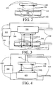
Fig. 2 is a plan view illustrating the desired alignment of a die and its die bond pads to via drop openings patterned in a metal mask layer of a flex substrate. -
Fig. 3 is a mixed plan and schematic view showing how a downward-looking camera is used to pinpoint via drop openings to which die bond pads are to be aligned. -
Fig. 4 is a mixed plan and schematic view showing how an upward-looking camera is used to pinpoint the locations of the die bond pads to be aligned with the via drop openings pinpointed inFig. 3 . -
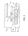
Fig. 5 is a mixed plan and schematic view showing how the die bond pads are then aligned and pressed into alignment with the via drop openings, following the processes ofFigs. 4 and5 . -
Fig. 6 is a graphical illustration of die placement accuracy obtained by prior art methods. -
Fig. 7 is a graphical illustration of the improvement in die placement accuracy obtained by an experimental reduction to practice of the invention. - Referring to
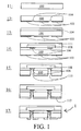
Fig. 1 , which from top to bottom illustrates a die alignment process according to one embodiment of the present invention, starting with aflex substrate 100 such as polyimide flex atstep 11, a mask for via formation is first deposited and patterned in a metal viamask layer 102 on the bottom surface of flex substrate 100 (step 12). Importantly, the pattern incorporates local reference features which precisely correspond to features on each die that will be placed on the frame. In particular,local fiducials 114 such as die drop locations are patterned directly into viamask layer 102. Viamask layer 102 does not ever have to be modified using adaptive lithography once die are placed, because the via mask layer is the reference upon which all die placements and interconnect patterns are subsequently based. - Die attach means 104 such as die attach adhesive is then applied to the top side of flex substrate 100 (step 13).
Bond pads 106 ondie 108 are locally aligned tolocal fiducials 114 patterned on metal viamask layer 102 and attached (using die attach means, e.g. adhesive 104) to flexsubstrate 100 with high accuracy, using a novel and inventive "adaptive die placement" apparatus and method (step 14). Adaptive die placement as disclosed herein will be described in greater detail in connection withFigs. 2 through 5 . The modules optionally may be encapsulated bymaterial 111 at this point, for example, in manner similar to that described in aforementionedU.S. Patent 5,527,741 . -
Vias 110 down to diebond pads 106 are then created (opened) by any of a variety of methods, such as plasma etching or excimer laser ablation, through the existing aligned metal viamask layer 102 on flex substrate 100 (step 15). Indeed, the use of viamask layer 102 for adaptive die placement has the side benefit of enabling a wide range of techniques to be used for via formation. - Finally,
interconnect metal 112 is then deposited (step 16), and patterned and etched (step 17). This results in a full chip scale package ormultichip module 1 followingstep 17. - Although the steps in
FIG. 1 are all shown as having the same orientation, typically steps 12 and 15-17 are more easily performed by inverting the structure. Additionally, the terms "top" and "bottom" are used for purposes of example only. -
Figs. 2 through 5 illustrate in further detail, the adaptive die placement leading to the configuration ofstep 14. Generally, there are three primary sources of die placement misalignment. Preparation of the frame for die placement may introduce distortion of theflex substrate 100 on the frame. Variability in placement of the frame within a die attach station may introduce translation and rotation errors for the entire frame. Errors in the calibration or interpolation of robot motion across its working area may result in misplacement of die with respect to fiducials between which the robot motions are interpolated. - These errors are accommodated so as to lead to the configuration resulting at
step 14, using adaptive die placement. In particular, as shown inFig. 2 , it is desired to achieve aclose alignment 302 between a selected pair ofdie bond pads 106 ofdie 108 and a corresponding selected pair oflocal fiducials 114, such as the illustrated via drop openings, patterned directly into viamask layer 102. - To achieve this, die 108 are loaded with the active surface face down. A downward-looking camera focuses on the reference features on a frame. A vision recognition system determines the location of reference features on the frame in a three-tiered hierarchy: "global" fiducials, "module" fiducials, and "local" fiducials. All of these fiducials are created at
step 12 as part and parcel of viamask layer 102. Global fiducials are coarse features which enable the system to compensate for gross misalignment or rotation of the entire frame. A first downward-looking camera with low-magnification moves to a pair of standardized coordinates and locates the global fiducials within its field of view. These two global fiducials establish the location and rotation of the frame. A second downward-looking camera with higher-magnification, 500, is positioned over the coordinates for each pair of module fiducials. Acquisition of each pair of module fiducials by this higher magnification camera partially corrects for distortion of the flex pattern across the frame. Aside from the fact that these fiducials are created as part of the patterning of viamask layer 102, the two above-described alignment steps are standard prior art practice for fabrication of chip-on-flex modules. - At this point, an additional novel and inventive alignment step takes place. High magnification, downward-looking
camera 500 is positioned over thelocal fiducials 114 of viamask layer 102 for each die to be placed, and the vision system acquires the position of each of these local fiducial 114 features (seeFig. 3 ). The advantage to this step is that the computed interpolation of the placement point for each die, based on the module fiducials, is superseded by the actual positions of local fiducial 114 features which correspond to the die placement. An example of this would be a field of metal having openings such as via drop openings acting aslocal fiducials 114 which correspond (302) to the desired placement locations ofdie bond pads 106 ondie 108. Alignment to two or more of these openings allows for more accurate placement of the die than does interpolation from a distant fiducial. Calibration errors, local distortions of the flex film, and other minor error sources are eliminated. The die is then "picked" by avacuum end effector 610 and brought over an upward-looking camera 600 (seeFig. 4 ). Upward-lookingcamera 600 has the same magnification as high magnification, downward-lookingcamera 500 which acquired the local fiducials. The position of thebond pads 106 on die 108 corresponding to the acquired features of thelocal fiducials 114 such as the via drop openings onflex substrate 100 are captured. This precisely determines the position and rotational orientation ofdie 108 and diebond pads 106 relative to vacuumend effector 610.Die 108 is then translated and rotated to match the desired position onflex substrate 100, and pressed against die attach means 104 onflex substrate 100. - In particular, as shown in detail in
Fig. 3 , downward-lookingcamera 500 emits light 510 from a light source associated therewith, toward and through die attachmeans 104 andflex substrate 100, each of which is translucent. Light rays which strike the metallic viamask layer 102 are reflected back toward downward-lookingcamera 500 while those directed toward thelocal fiducials 114 at the via drop openings pass throughflex substrate 100 and are not reflected back, thus enabling downward-lookingcamera 500 to detect the via drop openings. As illustrated schematically, acontrol system 502 accepts (506) vision recognition data from downward-lookingcamera 500, and determines and records precise positions and angular orientations of the via drop openings in the plane normal tolight path 510 as marked bylocal fiducials 114. Again, it is important to emphasize that in a preferred embodiment,local fiducials 114 are the via drop openings, which are directly patterned into metallic viamask layer 102. Anactuator 504 for precisely moving and angularly-orienting downward-lookingcamera 500 andflex substrate 100 relative to one another are controlled bycontrol system 502.Actuator 504 typically employ numerically-controlled robotic motion technologies known in the art. In a preferred embodiment,flex substrate 100 occupies a fixed location, and downward-lookingcamera 500 is moved relative thereto. It is understood, however, that alternative embodiments of the invention may actually move one or both of downward-lookingcamera 500 andflex substrate 100 on an absolute scale of motion to achieve the desired relative motion therebetween, and that numerous variations to achieve this relative motion within the scope of the appended claims would be apparent to someone of ordinary skill and is considered to be within the scope of this disclosure and its associated claims. - At this point, with suitable coordinates identified for via drop openings (local fiducials 114) and recorded in
control system 502, it is now known where onflex substrate 100die bond pads 106 -- once these are empirically located -- should be placed.Fig. 4 illustrates how diebond pads 106 are in fact empirically located, using upward-lookingcamera 600.Vacuum end effector 610 or a suitable substitute or equivalent picks up die 108 withdie bond pads 106.Further actuator 604 for precisely moving and angularly-orientingvacuum end effector 610 and upward-lookingcamera 600 relative to one another are also controlled bycontrol system 502.Further actuator 604 typically employ robotic motion technologies, and the same considerations noted earlier foractuator 504 apply here as well. Upward-lookingcamera 600 also emits light 615 from a light source associated therewith. Light reflected off ofdie bond pads 106 is thus used to detect the locations and angular orientations ofdie bond pads 106 relative to the known location and orientation ofvacuum end effector 610. As a result,control system 502 now has all the information needed to precisely align via drop openings (local fiducials 114) withdie bond pads 106, see again,Fig. 2 . - Thus, as now shown in
Fig. 5 ,control system 502 uses the information previously captured by downward-lookingcamera 500 and upward-lookingcamera 600 to actuate (i.e. move) (508, 608) diebond pads 106 into alignment with the via drop openings onflex substrate 100, using the numerically-controlled robotic motion technologies that causeactuation bond pads 106 are then pressed together withflex substrate 100 and in particular are pressed into die attachmeans 104 to complete the adaptive die placement. After (optional)encapsulation 111, the resulting configuration is that ofFig. 1 ,step 14. - This is an improvement over non-adaptive die attachment techniques wherein die are positioned relative to "fiducials" on the metal artwork pattern, stepping a certain X and Y distance from that location to where the die is supposed to be on the flex. If the stepping stage is not calibrated, or if the flex is distorted in any way, the die will be misplaced. The present invention is also an improvement over above-discussed adaptive lithography techniques which correct for the misplaced die by mapping where the misplaced die bond pads are and laser drilling a via to hit that location. In adaptive lithography techniques, the metal interconnect is also adjusted to hit the via, hence each artwork is different.
- The processes of forming the die-specific alignment features on the flex film by depositing and patterning metal via
mask layer 102 on the bottom surface offlex substrate 100, and aligning and placing die with respect to these features, as illustrated inFigs. 1 through 5 , comprise adaptive die placement as disclosed and understood herein. It should be noted that no adaptive lithography is necessary; indeed the elimination of adaptive lithography is a useful benefit of the invention. Again, die are placed in reference to the interconnect pattern as opposed to the interconnect pattern being corrected in reference to the die placement. - In the embodiment described above in which the die alignment features consist of a continuous field of metal (via mask layer 102) with
local fiducials 114 that actually double as via drop openings fordie bond pads 106, a second novel and inventive process enhancement may be realized. In conventional drilling processes., vias are drilled through a flex film to the die bond pads using an Argon-ion laser at 351nm in a serial process which is frequently time consuming, particularly for complex modules incorporating a number of high pin count devices. The step is further complicated by the necessity of aligning to and recording the position of each die, as mentioned above. By contrast, an identical module built using the above-described metal field for adaptive die placement already has a conformal mask (via mask layer 102) integrated onto the bottom surface offlex substrate 100. This mask can be used to form all the vias to the die bond pads (step 15) using any of a wide variety of methods (e.g., RIE, plasma etching, excimer ablation). These are all parallel methods, so the time required to form the vias is independent of the number of vias on the module. In short, the same viamask layer 102 that enables die 108 to be placed without these placements being later compensated by adaptive lithography also provides a conformal mask which enables vias 110 to be formed using a wide range of methods -- including parallel methods -- that cannot otherwise be employed for this purpose. - The need for adaptive lithography subsequent to the via drilling step is dependent only on the flex distortion, since the die and vias are located with respect to the preexisting alignment pattern on the flex.
- An advantage of the use of local alignment features for precision placement of the die on the flex surface is that by aligning to a conformal via
mask layer 102 for the subsequent via-forming step, precise alignment of the vias to the pads is ensured 1) without requiring an additional alignment / adaptation iteration, 2) without a serial laser via-drilling operation, and (3) without depending on the flow properties of the die attach adhesive. The conformal alignment layer (via mask layer 102) disclosed herein overcomes the many prior art limitations noted earlier. - In an experimental reduction to practice, KAPTON® polyimide (KAPTON® is a trademark of DuPont Co.) flex (12.7µm, 0.5 mil thick) was metallized on both sides (top layer 12nm thick Ti / bottom layer 4.3µm thick Brite Cu), patterned, and etched. The top (die) side was patterned with an interconnect test pattern, and the upper side of the interconnect test pattern was patterned with via openings. After metal etching, die attach adhesive was applied. Die were then attached using adaptive die placement with alignment to the patterned metal via openings. The accuracy of the alignment is shown in
Fig. 7 . Adaptive dye placement can be done within a 25µm, target with Zst = 5.98 σ, which significantly improves on Zst = 1.79 σ for non-adaptive methods shown inFig. 6 . - After placement, the die attach adhesive was cured. The vias were then opened using two methods, laser excimer ablation (248nm KrFI excimer130 mJ, 300 repeats), and reactive ion etching (36 sccm CF4 / 4 sccm O2, 20.7Pa (155mtorr), 500W) through the openings in the already aligned metal via mask.
- The vias opened using reactive ion etching were larger than the excimer ablated vias due to lateral etching that occurred with the RIE conditions used. A more anisotropic etch is possible, which among other benefits, helps to avoid sharp via corners.
Claims (5)
- A method for aligning (302) dies (108) to a via mask layer (102) on a flex substrate (100) to produce at least one electronic chip package (1), comprising the steps of:patterning (12) a mask for via formation in said via mask layer (102) on a bottom surface of said flex substrate, characterized by:adaptively aligning (302) the bond pads (106) of each die (108) to at least one local fiducial (114) of said via mask layer; comprisinglocating global fiducials, defining coarse features which enable compensation for gross misalignment or rotation, using a first downward-looking camera with a first low-magnification by moving the first downward-looking camera to a pair of standardized coordinates and locating the global fiducials within its field of view;locating a pair of module fiducials that define local fiducials (114) using a second downward-looking camera (500) with a high magnification that is higher than said first magnification;wherein the second downward looking camera (500) emits light (510) from a light source toward and through a die attach means (104) and the flex substrate (100), each of which is translucent, and wherein light rays which strike the via mask layer (102) are reflected back toward the second downward looking camera (500) while those directed toward the local fiducials (114) at via drop openings pass through the flex substrate (100) and are not reflected back, thus enabling the second downward looking camera (500) to detect the via drop openings;acquiring the actual positions of each of the local fiducials;bringing the die over an upward-looking camera (600), and locating said bond pads (106) using the upward-looking camera (600), which has the same magnification as the second downward-looking camera (500);wherein the upward looking camera (600) also emits light (615) from a light source, where said light (615) is reflected off of die bond pads (106) and used to detect the locations and angular orientations of the die bond pads (106) relative to the known location and orientation of a vacuum end effector (610); andadaptively aligning said bond pads and said local fiducials with one another based upon the locations of said local fiducials (114) located by said second downward-looking camera (500) and the locations of said bond pads (106) located by said upward-looking camera (600), using a control system (502) and actuator.
- The method of claim 1, comprising the further step of attaching said bond pads (106) to a top surface of said flex substrate (100).
- The method of claim 2, said local fiducials (114) comprising via drop openings, comprising the further step of opening vias from said bottom surface of said flex substrate (100) to said bond pads (106) at said via drop openings.
- The method of claim 3, comprising the further step of: depositing, patterning and etching interconnect metal upon said bottom surface of said flex substrate (100).
- The method of claim 2, wherein attaching said bond pads (106) to said top surface of said flex substrate (100) comprises using an adhesive.
Applications Claiming Priority (2)
| Application Number | Priority Date | Filing Date | Title |
|---|---|---|---|
| US09/469,749 US6475877B1 (en) | 1999-12-22 | 1999-12-22 | Method for aligning die to interconnect metal on flex substrate |
| US469749 | 1999-12-22 |
Publications (3)
| Publication Number | Publication Date |
|---|---|
| EP1111662A2 EP1111662A2 (en) | 2001-06-27 |
| EP1111662A3 EP1111662A3 (en) | 2003-10-01 |
| EP1111662B1 true EP1111662B1 (en) | 2012-12-12 |
Family
ID=23864927
Family Applications (1)
| Application Number | Title | Priority Date | Filing Date |
|---|---|---|---|
| EP00311553A Expired - Lifetime EP1111662B1 (en) | 1999-12-22 | 2000-12-21 | Method for aligning semiconductor die to interconnect metal on flex substrate |
Country Status (5)
| Country | Link |
|---|---|
| US (2) | US6475877B1 (en) |
| EP (1) | EP1111662B1 (en) |
| JP (1) | JP4931277B2 (en) |
| CN (1) | CN1199250C (en) |
| TW (1) | TW490716B (en) |
Cited By (1)
| Publication number | Priority date | Publication date | Assignee | Title |
|---|---|---|---|---|
| US11778751B2 (en) | 2019-12-05 | 2023-10-03 | At&S Austria Technologie & Systemtechnik Aktiengesellschaft | Compensating misalignment of component carrier feature by modifying target design concerning correlated component carrier feature |
Families Citing this family (61)
| Publication number | Priority date | Publication date | Assignee | Title |
|---|---|---|---|---|
| US6888240B2 (en) | 2001-04-30 | 2005-05-03 | Intel Corporation | High performance, low cost microelectronic circuit package with interposer |
| US6894399B2 (en) | 2001-04-30 | 2005-05-17 | Intel Corporation | Microelectronic device having signal distribution functionality on an interfacial layer thereof |
| US7071024B2 (en) | 2001-05-21 | 2006-07-04 | Intel Corporation | Method for packaging a microelectronic device using on-die bond pad expansion |
| US7183658B2 (en) | 2001-09-05 | 2007-02-27 | Intel Corporation | Low cost microelectronic circuit package |
| JP3645511B2 (en) * | 2001-10-09 | 2005-05-11 | 株式会社ルネサステクノロジ | Manufacturing method of semiconductor device |
| US8455994B2 (en) * | 2002-01-31 | 2013-06-04 | Imbera Electronics Oy | Electronic module with feed through conductor between wiring patterns |
| FI119215B (en) * | 2002-01-31 | 2008-08-29 | Imbera Electronics Oy | A method for immersing a component in a substrate and an electronic module |
| FI115285B (en) * | 2002-01-31 | 2005-03-31 | Imbera Electronics Oy | Method of immersing a component in a base material and forming a contact |
| US6964881B2 (en) * | 2002-08-27 | 2005-11-15 | Micron Technology, Inc. | Multi-chip wafer level system packages and methods of forming same |
| US6855953B2 (en) * | 2002-12-20 | 2005-02-15 | Itt Manufacturing Enterprises, Inc. | Electronic circuit assembly having high contrast fiducial |
| US7263677B1 (en) * | 2002-12-31 | 2007-08-28 | Cadence Design Systems, Inc. | Method and apparatus for creating efficient vias between metal layers in semiconductor designs and layouts |
| US8704359B2 (en) | 2003-04-01 | 2014-04-22 | Ge Embedded Electronics Oy | Method for manufacturing an electronic module and an electronic module |
| FI115601B (en) * | 2003-04-01 | 2005-05-31 | Imbera Electronics Oy | Method for manufacturing an electronic module and an electronic module |
| US8222723B2 (en) | 2003-04-01 | 2012-07-17 | Imbera Electronics Oy | Electric module having a conductive pattern layer |
| CN1302541C (en) * | 2003-07-08 | 2007-02-28 | 敦南科技股份有限公司 | Chip packaging base plate having flexible circuit board and method for manufacturing the same |
| FI20031201A (en) * | 2003-08-26 | 2005-02-27 | Imbera Electronics Oy | Procedure for manufacturing an electronics module and an electronics module |
| FI20031341A (en) | 2003-09-18 | 2005-03-19 | Imbera Electronics Oy | Method for manufacturing an electronic module |
| TWI237883B (en) * | 2004-05-11 | 2005-08-11 | Via Tech Inc | Chip embedded package structure and process thereof |
| FI117814B (en) * | 2004-06-15 | 2007-02-28 | Imbera Electronics Oy | A method for manufacturing an electronic module |
| TWI250596B (en) * | 2004-07-23 | 2006-03-01 | Ind Tech Res Inst | Wafer-level chip scale packaging method |
| FI117812B (en) * | 2004-08-05 | 2007-02-28 | Imbera Electronics Oy | Manufacture of a layer containing a component |
| US8487194B2 (en) * | 2004-08-05 | 2013-07-16 | Imbera Electronics Oy | Circuit board including an embedded component |
| FI117369B (en) | 2004-11-26 | 2006-09-15 | Imbera Electronics Oy | Procedure for manufacturing an electronics module |
| WO2006080388A1 (en) * | 2005-01-28 | 2006-08-03 | Matsushita Electric Industrial Co., Ltd. | Electronic element package manufacturing method and electronic element package |
| FI122128B (en) * | 2005-06-16 | 2011-08-31 | Imbera Electronics Oy | Process for manufacturing circuit board design |
| DE112006001506T5 (en) | 2005-06-16 | 2008-04-30 | Imbera Electronics Oy | Board structure and method for its production |
| FI119714B (en) | 2005-06-16 | 2009-02-13 | Imbera Electronics Oy | Circuit board structure and method for manufacturing a circuit board structure |
| US20070012965A1 (en) * | 2005-07-15 | 2007-01-18 | General Electric Company | Photodetection system and module |
| JP4487875B2 (en) * | 2005-07-20 | 2010-06-23 | セイコーエプソン株式会社 | Method for manufacturing electronic substrate, method for manufacturing electro-optical device, and method for manufacturing electronic device |
| US9601474B2 (en) * | 2005-07-22 | 2017-03-21 | Invensas Corporation | Electrically stackable semiconductor wafer and chip packages |
| KR100785014B1 (en) * | 2006-04-14 | 2007-12-12 | 삼성전자주식회사 | Micro-electro mechanical system device using silicon on insulator wafer and method of manufacturing the same |
| JP5091600B2 (en) * | 2006-09-29 | 2012-12-05 | 三洋電機株式会社 | Semiconductor module, semiconductor module manufacturing method, and portable device |
| US7579215B2 (en) * | 2007-03-30 | 2009-08-25 | Motorola, Inc. | Method for fabricating a low cost integrated circuit (IC) package |
| US9953910B2 (en) * | 2007-06-21 | 2018-04-24 | General Electric Company | Demountable interconnect structure |
| US20080313894A1 (en) * | 2007-06-21 | 2008-12-25 | General Electric Company | Method for making an interconnect structure and low-temperature interconnect component recovery process |
| US20080318055A1 (en) * | 2007-06-21 | 2008-12-25 | General Electric Company | Recoverable electronic component |
| US20080318054A1 (en) * | 2007-06-21 | 2008-12-25 | General Electric Company | Low-temperature recoverable electronic component |
| US20080318413A1 (en) * | 2007-06-21 | 2008-12-25 | General Electric Company | Method for making an interconnect structure and interconnect component recovery process |
| US9610758B2 (en) * | 2007-06-21 | 2017-04-04 | General Electric Company | Method of making demountable interconnect structure |
| US20090028491A1 (en) | 2007-07-26 | 2009-01-29 | General Electric Company | Interconnect structure |
| CN101373748B (en) * | 2007-08-20 | 2011-06-15 | 宏茂微电子(上海)有限公司 | Wafer-class encapsulation structure and preparation method thereof |
| JP4966156B2 (en) * | 2007-10-23 | 2012-07-04 | ソニーケミカル&インフォメーションデバイス株式会社 | Wiring board cradle, wiring board connecting device and method using the same |
| WO2009081746A1 (en) * | 2007-12-21 | 2009-07-02 | Tokyo Seimitsu Co., Ltd. | Dicing apparatus and dicing method |
| JP4840373B2 (en) * | 2008-01-31 | 2011-12-21 | カシオ計算機株式会社 | Semiconductor device and manufacturing method thereof |
| FI123205B (en) | 2008-05-12 | 2012-12-31 | Imbera Electronics Oy | A circuit module and a method for manufacturing a circuit module |
| EP2342958B1 (en) | 2008-10-30 | 2020-06-17 | AT & S Austria Technologie & Systemtechnik Aktiengesellschaft | Method for integrating an electronic component into a printed circuit board |
| US8008781B2 (en) | 2008-12-02 | 2011-08-30 | General Electric Company | Apparatus and method for reducing pitch in an integrated circuit |
| US7964974B2 (en) | 2008-12-02 | 2011-06-21 | General Electric Company | Electronic chip package with reduced contact pad pitch |
| US7897481B2 (en) * | 2008-12-05 | 2011-03-01 | Taiwan Semiconductor Manufacturing Company, Ltd. | High throughput die-to-wafer bonding using pre-alignment |
| US20120155038A1 (en) * | 2009-11-30 | 2012-06-21 | Sharp Kabushiki Kaisha | Flexible circuit board and manufacturing method thereof |
| US8623689B2 (en) * | 2010-07-07 | 2014-01-07 | Ineffable Cellular Limited Liability Company | Package process of backside illumination image sensor |
| JP5399542B2 (en) * | 2012-08-08 | 2014-01-29 | 富士通株式会社 | Manufacturing method of semiconductor device |
| JP5554380B2 (en) * | 2012-08-08 | 2014-07-23 | 富士通株式会社 | Semiconductor device |
| CN104584207A (en) * | 2012-12-21 | 2015-04-29 | 松下知识产权经营株式会社 | Electronic component package and method for manufacturing same |
| US9825209B2 (en) | 2012-12-21 | 2017-11-21 | Panasonic Intellectual Property Management Co., Ltd. | Electronic component package and method for manufacturing the same |
| WO2014097642A1 (en) * | 2012-12-21 | 2014-06-26 | パナソニック株式会社 | Electronic component package and method for manufacturing same |
| CN104603932A (en) * | 2012-12-21 | 2015-05-06 | 松下知识产权经营株式会社 | Electronic component package and method for producing same |
| US20150206819A1 (en) * | 2012-12-21 | 2015-07-23 | Panasonic Intellectual Property Management Co., Ltd. | Electronic component package and method for manufacturing the same |
| DE102015214219A1 (en) * | 2015-07-28 | 2017-02-02 | Osram Opto Semiconductors Gmbh | Method for producing a component and a component |
| WO2018098649A1 (en) * | 2016-11-30 | 2018-06-07 | 深圳修远电子科技有限公司 | Integrated circuit packaging method and integrated packaged circuit |
| EP3557608A1 (en) | 2018-04-19 | 2019-10-23 | AT & S Austria Technologie & Systemtechnik Aktiengesellschaft | Packaged integrated circuit with interposing functionality and method for manufacturing such a packaged integrated circuit |
Citations (1)
| Publication number | Priority date | Publication date | Assignee | Title |
|---|---|---|---|---|
| JPH09232363A (en) * | 1996-02-23 | 1997-09-05 | Toshiba Corp | Alignment method and bonding device for semiconductor chip |
Family Cites Families (18)
| Publication number | Priority date | Publication date | Assignee | Title |
|---|---|---|---|---|
| US4783695A (en) | 1986-09-26 | 1988-11-08 | General Electric Company | Multichip integrated circuit packaging configuration and method |
| US4933042A (en) | 1986-09-26 | 1990-06-12 | General Electric Company | Method for packaging integrated circuit chips employing a polymer film overlay layer |
| US4835704A (en) | 1986-12-29 | 1989-05-30 | General Electric Company | Adaptive lithography system to provide high density interconnect |
| US5192716A (en) * | 1989-01-25 | 1993-03-09 | Polylithics, Inc. | Method of making a extended integration semiconductor structure |
| US5055907A (en) * | 1989-01-25 | 1991-10-08 | Mosaic, Inc. | Extended integration semiconductor structure with wiring layers |
| JP2803221B2 (en) * | 1989-09-19 | 1998-09-24 | 松下電器産業株式会社 | IC mounting apparatus and method |
| US5194948A (en) * | 1991-04-26 | 1993-03-16 | At&T Bell Laboratories | Article alignment method and apparatus |
| JPH05152794A (en) * | 1991-11-29 | 1993-06-18 | Sharp Corp | Ic chip mounting apparatus |
| JPH06338538A (en) * | 1993-05-28 | 1994-12-06 | Nippon Chemicon Corp | Connection method of semiconductor element |
| US5527741A (en) * | 1994-10-11 | 1996-06-18 | Martin Marietta Corporation | Fabrication and structures of circuit modules with flexible interconnect layers |
| GB9610689D0 (en) * | 1996-05-22 | 1996-07-31 | Int Computers Ltd | Flip chip attachment |
| US5920123A (en) * | 1997-01-24 | 1999-07-06 | Micron Technology, Inc. | Multichip module assembly having via contacts and method of making the same |
| JP3160252B2 (en) * | 1997-12-11 | 2001-04-25 | イビデン株式会社 | Manufacturing method of multilayer printed wiring board |
| JP3919972B2 (en) * | 1998-07-31 | 2007-05-30 | セイコーエプソン株式会社 | Manufacturing method of semiconductor device |
| US6246010B1 (en) * | 1998-11-25 | 2001-06-12 | 3M Innovative Properties Company | High density electronic package |
| US6284564B1 (en) | 1999-09-20 | 2001-09-04 | Lockheed Martin Corp. | HDI chip attachment method for reduced processing |
| US6242282B1 (en) * | 1999-10-04 | 2001-06-05 | General Electric Company | Circuit chip package and fabrication method |
| US6271469B1 (en) * | 1999-11-12 | 2001-08-07 | Intel Corporation | Direct build-up layer on an encapsulated die package |
-
1999
- 1999-12-22 US US09/469,749 patent/US6475877B1/en not_active Expired - Lifetime
-
2000
- 2000-12-11 TW TW089126381A patent/TW490716B/en not_active IP Right Cessation
- 2000-12-21 EP EP00311553A patent/EP1111662B1/en not_active Expired - Lifetime
- 2000-12-21 JP JP2000388006A patent/JP4931277B2/en not_active Expired - Lifetime
- 2000-12-22 CN CNB001364499A patent/CN1199250C/en not_active Expired - Lifetime
-
2002
- 2002-07-22 US US10/199,296 patent/US6790703B2/en not_active Expired - Lifetime
Patent Citations (1)
| Publication number | Priority date | Publication date | Assignee | Title |
|---|---|---|---|---|
| JPH09232363A (en) * | 1996-02-23 | 1997-09-05 | Toshiba Corp | Alignment method and bonding device for semiconductor chip |
Cited By (1)
| Publication number | Priority date | Publication date | Assignee | Title |
|---|---|---|---|---|
| US11778751B2 (en) | 2019-12-05 | 2023-10-03 | At&S Austria Technologie & Systemtechnik Aktiengesellschaft | Compensating misalignment of component carrier feature by modifying target design concerning correlated component carrier feature |
Also Published As
| Publication number | Publication date |
|---|---|
| JP2001250888A (en) | 2001-09-14 |
| TW490716B (en) | 2002-06-11 |
| CN1199250C (en) | 2005-04-27 |
| JP4931277B2 (en) | 2012-05-16 |
| US6475877B1 (en) | 2002-11-05 |
| CN1301039A (en) | 2001-06-27 |
| EP1111662A3 (en) | 2003-10-01 |
| US6790703B2 (en) | 2004-09-14 |
| US20020197767A1 (en) | 2002-12-26 |
| EP1111662A2 (en) | 2001-06-27 |
Similar Documents
| Publication | Publication Date | Title |
|---|---|---|
| EP1111662B1 (en) | Method for aligning semiconductor die to interconnect metal on flex substrate | |
| EP1158570B1 (en) | Vertical interconnect process for silicon segments | |
| US6255726B1 (en) | Vertical interconnect process for silicon segments with dielectric isolation | |
| US6080596A (en) | Method for forming vertical interconnect process for silicon segments with dielectric isolation | |
| US7019223B2 (en) | Solder resist opening to define a combination pin one indicator and fiducial | |
| US6982475B1 (en) | Hermetic wafer scale integrated circuit structure | |
| US7205181B1 (en) | Method of forming hermetic wafer scale integrated circuit structure | |
| US8609539B2 (en) | Embedded semiconductor device substrate and production method thereof | |
| EP1029360A2 (en) | Vertical interconnect process for silicon segments with dielectric isolation | |
| US5843806A (en) | Methods for packaging tab-BGA integrated circuits | |
| US7030508B2 (en) | Substrate for semiconductor package and wire bonding method using thereof | |
| US6975040B2 (en) | Fabricating semiconductor chips | |
| EP0517198B1 (en) | Thin film magnetic head structure and methods of fabricating the same | |
| JP4100728B2 (en) | Adaptive method and apparatus for electrical interconnection | |
| CN1050930C (en) | Method for automatically welding package of ball array integrated circuit by coil belt | |
| JP3301112B2 (en) | Method for manufacturing multi-chip package type semiconductor device | |
| CN1068710C (en) | Method for automatically welding package of ball array integrated circuit by coil belt | |
| JPH07240431A (en) | Alignment mark of circuit board and its manufacture |
Legal Events
| Date | Code | Title | Description |
|---|---|---|---|
| PUAI | Public reference made under article 153(3) epc to a published international application that has entered the european phase |
Free format text: ORIGINAL CODE: 0009012 |
|
| AK | Designated contracting states |
Kind code of ref document: A2 Designated state(s): AT BE CH CY DE DK ES FI FR GB GR IE IT LI LU MC NL PT SE TR |
|
| AX | Request for extension of the european patent |
Free format text: AL;LT;LV;MK;RO;SI |
|
| PUAL | Search report despatched |
Free format text: ORIGINAL CODE: 0009013 |
|
| AK | Designated contracting states |
Kind code of ref document: A3 Designated state(s): AT BE CH CY DE DK ES FI FR GB GR IE IT LI LU MC NL PT SE TR |
|
| AX | Request for extension of the european patent |
Extension state: AL LT LV MK RO SI |
|
| 17P | Request for examination filed |
Effective date: 20040401 |
|
| 17Q | First examination report despatched |
Effective date: 20040506 |
|
| AKX | Designation fees paid |
Designated state(s): DE FR |
|
| RIC1 | Information provided on ipc code assigned before grant |
Ipc: H01L 21/60 20060101ALI20120426BHEP Ipc: H01L 21/68 20060101ALI20120426BHEP Ipc: H01L 21/00 20060101AFI20120426BHEP Ipc: H01L 23/00 20060101ALI20120426BHEP Ipc: H01L 23/538 20060101ALI20120426BHEP |
|
| GRAP | Despatch of communication of intention to grant a patent |
Free format text: ORIGINAL CODE: EPIDOSNIGR1 |
|
| GRAS | Grant fee paid |
Free format text: ORIGINAL CODE: EPIDOSNIGR3 |
|
| GRAA | (expected) grant |
Free format text: ORIGINAL CODE: 0009210 |
|
| AK | Designated contracting states |
Kind code of ref document: B1 Designated state(s): DE FR |
|
| REG | Reference to a national code |
Ref country code: DE Ref legal event code: R096 Ref document number: 60047692 Country of ref document: DE Effective date: 20130207 |
|
| PLBE | No opposition filed within time limit |
Free format text: ORIGINAL CODE: 0009261 |
|
| STAA | Information on the status of an ep patent application or granted ep patent |
Free format text: STATUS: NO OPPOSITION FILED WITHIN TIME LIMIT |
|
| 26N | No opposition filed |
Effective date: 20130913 |
|
| REG | Reference to a national code |
Ref country code: DE Ref legal event code: R097 Ref document number: 60047692 Country of ref document: DE Effective date: 20130913 |
|
| REG | Reference to a national code |
Ref country code: FR Ref legal event code: PLFP Year of fee payment: 16 |
|
| REG | Reference to a national code |
Ref country code: FR Ref legal event code: PLFP Year of fee payment: 17 |
|
| REG | Reference to a national code |
Ref country code: FR Ref legal event code: PLFP Year of fee payment: 18 |
|
| PGFP | Annual fee paid to national office [announced via postgrant information from national office to epo] |
Ref country code: DE Payment date: 20191119 Year of fee payment: 20 |
|
| PGFP | Annual fee paid to national office [announced via postgrant information from national office to epo] |
Ref country code: FR Payment date: 20191120 Year of fee payment: 20 |
|
| REG | Reference to a national code |
Ref country code: DE Ref legal event code: R071 Ref document number: 60047692 Country of ref document: DE |