EP1111489A1 - Two-dimensional positioning apparatus and method for measuring laser light from the apparatus - Google Patents
Two-dimensional positioning apparatus and method for measuring laser light from the apparatus Download PDFInfo
- Publication number
- EP1111489A1 EP1111489A1 EP00123536A EP00123536A EP1111489A1 EP 1111489 A1 EP1111489 A1 EP 1111489A1 EP 00123536 A EP00123536 A EP 00123536A EP 00123536 A EP00123536 A EP 00123536A EP 1111489 A1 EP1111489 A1 EP 1111489A1
- Authority
- EP
- European Patent Office
- Prior art keywords
- axis
- signal
- slider
- positioning apparatus
- signals
- Prior art date
- Legal status (The legal status is an assumption and is not a legal conclusion. Google has not performed a legal analysis and makes no representation as to the accuracy of the status listed.)
- Granted
Links
Images





Classifications
-
- G—PHYSICS
- G03—PHOTOGRAPHY; CINEMATOGRAPHY; ANALOGOUS TECHNIQUES USING WAVES OTHER THAN OPTICAL WAVES; ELECTROGRAPHY; HOLOGRAPHY
- G03F—PHOTOMECHANICAL PRODUCTION OF TEXTURED OR PATTERNED SURFACES, e.g. FOR PRINTING, FOR PROCESSING OF SEMICONDUCTOR DEVICES; MATERIALS THEREFOR; ORIGINALS THEREFOR; APPARATUS SPECIALLY ADAPTED THEREFOR
- G03F7/00—Photomechanical, e.g. photolithographic, production of textured or patterned surfaces, e.g. printing surfaces; Materials therefor, e.g. comprising photoresists; Apparatus specially adapted therefor
- G03F7/70—Microphotolithographic exposure; Apparatus therefor
- G03F7/70691—Handling of masks or workpieces
- G03F7/70716—Stages
-
- G—PHYSICS
- G01—MEASURING; TESTING
- G01B—MEASURING LENGTH, THICKNESS OR SIMILAR LINEAR DIMENSIONS; MEASURING ANGLES; MEASURING AREAS; MEASURING IRREGULARITIES OF SURFACES OR CONTOURS
- G01B9/00—Measuring instruments characterised by the use of optical techniques
- G01B9/02—Interferometers
- G01B9/02015—Interferometers characterised by the beam path configuration
- G01B9/02017—Interferometers characterised by the beam path configuration with multiple interactions between the target object and light beams, e.g. beam reflections occurring from different locations
- G01B9/02019—Interferometers characterised by the beam path configuration with multiple interactions between the target object and light beams, e.g. beam reflections occurring from different locations contacting different points on same face of object
-
- G—PHYSICS
- G01—MEASURING; TESTING
- G01B—MEASURING LENGTH, THICKNESS OR SIMILAR LINEAR DIMENSIONS; MEASURING ANGLES; MEASURING AREAS; MEASURING IRREGULARITIES OF SURFACES OR CONTOURS
- G01B9/00—Measuring instruments characterised by the use of optical techniques
- G01B9/02—Interferometers
- G01B9/02015—Interferometers characterised by the beam path configuration
- G01B9/02017—Interferometers characterised by the beam path configuration with multiple interactions between the target object and light beams, e.g. beam reflections occurring from different locations
- G01B9/02021—Interferometers characterised by the beam path configuration with multiple interactions between the target object and light beams, e.g. beam reflections occurring from different locations contacting different faces of object, e.g. opposite faces
-
- G—PHYSICS
- G01—MEASURING; TESTING
- G01B—MEASURING LENGTH, THICKNESS OR SIMILAR LINEAR DIMENSIONS; MEASURING ANGLES; MEASURING AREAS; MEASURING IRREGULARITIES OF SURFACES OR CONTOURS
- G01B9/00—Measuring instruments characterised by the use of optical techniques
- G01B9/02—Interferometers
- G01B9/02055—Reduction or prevention of errors; Testing; Calibration
- G01B9/02075—Reduction or prevention of errors; Testing; Calibration of particular errors
- G01B9/02078—Caused by ambiguity
- G01B9/02079—Quadrature detection, i.e. detecting relatively phase-shifted signals
- G01B9/02081—Quadrature detection, i.e. detecting relatively phase-shifted signals simultaneous quadrature detection, e.g. by spatial phase shifting
-
- G—PHYSICS
- G03—PHOTOGRAPHY; CINEMATOGRAPHY; ANALOGOUS TECHNIQUES USING WAVES OTHER THAN OPTICAL WAVES; ELECTROGRAPHY; HOLOGRAPHY
- G03F—PHOTOMECHANICAL PRODUCTION OF TEXTURED OR PATTERNED SURFACES, e.g. FOR PRINTING, FOR PROCESSING OF SEMICONDUCTOR DEVICES; MATERIALS THEREFOR; ORIGINALS THEREFOR; APPARATUS SPECIALLY ADAPTED THEREFOR
- G03F7/00—Photomechanical, e.g. photolithographic, production of textured or patterned surfaces, e.g. printing surfaces; Materials therefor, e.g. comprising photoresists; Apparatus specially adapted therefor
- G03F7/70—Microphotolithographic exposure; Apparatus therefor
- G03F7/70691—Handling of masks or workpieces
- G03F7/70775—Position control, e.g. interferometers or encoders for determining the stage position
-
- G—PHYSICS
- G05—CONTROLLING; REGULATING
- G05B—CONTROL OR REGULATING SYSTEMS IN GENERAL; FUNCTIONAL ELEMENTS OF SUCH SYSTEMS; MONITORING OR TESTING ARRANGEMENTS FOR SUCH SYSTEMS OR ELEMENTS
- G05B19/00—Program-control systems
- G05B19/02—Program-control systems electric
- G05B19/18—Numerical control [NC], i.e. automatically operating machines, in particular machine tools, e.g. in a manufacturing environment, so as to execute positioning, movement or co-ordinated operations by means of program data in numerical form
- G05B19/19—Numerical control [NC], i.e. automatically operating machines, in particular machine tools, e.g. in a manufacturing environment, so as to execute positioning, movement or co-ordinated operations by means of program data in numerical form characterised by positioning or contouring control systems, e.g. to control position from one programmed point to another or to control movement along a programmed continuous path
- G05B19/21—Numerical control [NC], i.e. automatically operating machines, in particular machine tools, e.g. in a manufacturing environment, so as to execute positioning, movement or co-ordinated operations by means of program data in numerical form characterised by positioning or contouring control systems, e.g. to control position from one programmed point to another or to control movement along a programmed continuous path using an incremental digital measuring device
- G05B19/23—Numerical control [NC], i.e. automatically operating machines, in particular machine tools, e.g. in a manufacturing environment, so as to execute positioning, movement or co-ordinated operations by means of program data in numerical form characterised by positioning or contouring control systems, e.g. to control position from one programmed point to another or to control movement along a programmed continuous path using an incremental digital measuring device for point-to-point control
- G05B19/231—Numerical control [NC], i.e. automatically operating machines, in particular machine tools, e.g. in a manufacturing environment, so as to execute positioning, movement or co-ordinated operations by means of program data in numerical form characterised by positioning or contouring control systems, e.g. to control position from one programmed point to another or to control movement along a programmed continuous path using an incremental digital measuring device for point-to-point control the positional error is used to control continuously the servomotor according to its magnitude
-
- H—ELECTRICITY
- H02—GENERATION; CONVERSION OR DISTRIBUTION OF ELECTRIC POWER
- H02K—DYNAMO-ELECTRIC MACHINES
- H02K41/00—Propulsion systems in which a rigid body is moved along a path due to dynamo-electric interaction between the body and a magnetic field travelling along the path
- H02K41/02—Linear motors; Sectional motors
- H02K41/03—Synchronous motors; Motors moving step by step; Reluctance motors
- H02K41/031—Synchronous motors; Motors moving step by step; Reluctance motors of the permanent magnet type
- H02K41/033—Synchronous motors; Motors moving step by step; Reluctance motors of the permanent magnet type with armature and magnets on one member, the other member being a flux distributor
-
- G—PHYSICS
- G01—MEASURING; TESTING
- G01B—MEASURING LENGTH, THICKNESS OR SIMILAR LINEAR DIMENSIONS; MEASURING ANGLES; MEASURING AREAS; MEASURING IRREGULARITIES OF SURFACES OR CONTOURS
- G01B2290/00—Aspects of interferometers not specifically covered by any group under G01B9/02
- G01B2290/70—Using polarization in the interferometer
-
- G—PHYSICS
- G05—CONTROLLING; REGULATING
- G05B—CONTROL OR REGULATING SYSTEMS IN GENERAL; FUNCTIONAL ELEMENTS OF SUCH SYSTEMS; MONITORING OR TESTING ARRANGEMENTS FOR SUCH SYSTEMS OR ELEMENTS
- G05B2219/00—Program-control systems
- G05B2219/30—Nc systems
- G05B2219/37—Measurements
- G05B2219/37275—Laser, interferometer
-
- G—PHYSICS
- G05—CONTROLLING; REGULATING
- G05B—CONTROL OR REGULATING SYSTEMS IN GENERAL; FUNCTIONAL ELEMENTS OF SUCH SYSTEMS; MONITORING OR TESTING ARRANGEMENTS FOR SUCH SYSTEMS OR ELEMENTS
- G05B2219/00—Program-control systems
- G05B2219/30—Nc systems
- G05B2219/49—Nc machine tool, till multiple
- G05B2219/49276—Floating, air, magnetic suspension xy table, sawyer motor, xenetics
-
- H—ELECTRICITY
- H02—GENERATION; CONVERSION OR DISTRIBUTION OF ELECTRIC POWER
- H02K—DYNAMO-ELECTRIC MACHINES
- H02K11/00—Structural association of dynamo-electric machines with electric components or with devices for shielding, monitoring or protection
-
- H—ELECTRICITY
- H02—GENERATION; CONVERSION OR DISTRIBUTION OF ELECTRIC POWER
- H02K—DYNAMO-ELECTRIC MACHINES
- H02K2201/00—Specific aspects not provided for in the other groups of this subclass relating to the magnetic circuits
- H02K2201/18—Machines moving with multiple degrees of freedom
Definitions
- the present invention is applicable to probers, handlers, steppers and other equipment and relates to two-dimensional positioning apparatus for positioning objects in a two-dimensional direction.
- FIG. 1 is a schematic view of the above-mentioned apparatus.
- a platen 10 which is made of a magnetic material, is provided with teeth formed at fixed spacings in the X-axis and Y-axis directions.
- the figure shows only part of the teeth, however, for simplification.
- An object being positioned is placed on a slider 11.
- Levitating means 12 causes the slider 11 to levitate above the platen 10. Nozzles are formed on the surface of the slider 11 facing the platen 10. Jets of compressed air are sent out through the nozzles by the levitating means 12 to produce levitational force.
- a Y-axis motor 13 is mounted on the slider 11 and teeth 132 are formed on the Y-axis motor 13 at fixed spacings in the Y-axis direction.
- the Y-axis motor 13 produces magnetic attractive force between the teeth 132 and the teeth 101 of the platen 10 to cause the slider 11 to move in the Y-axis direction.
- X-axis motors 14 and 15 are mounted on the slider 11 to be symmetrically opposite with each other in relation to the center point of the slider 11. Teeth 141 and 151 are formed on the X-axis motors 14 and 15 at fixed spacings in the X-axis direction. The X-axis motors 14 and 15 produce magnetic attractive force between the teeth 141 and 101 and between the teeth 151 and 101, to cause the slider 11 to move in the X-axis direction.
- Connecting members 111 and 112 connect the Y-axis motor 13 with both the X-axis motors 14 and 15.
- An X-axis mirror 16 is attached to one side of the platen 10, and a mirror surface is formed in the Y-axis direction.
- a Y-axis mirror 17 is attached to another side adjacent to the above-mentioned side of the platen 10, and a mirror surface is formed in the X-axis direction.
- a Y-axis position sensor 18, which is mounted on the Y-axis motor 13, is a laser interferometer that emits light beams to the Y-axis mirror 17, receives catoptric light beams from the Y-axis mirror 17, and detects the Y-axis position of the slider 11 by means of optical interference.
- X-axis position sensors 19 and 20 which are mounted on the X-axis motors 14 and 15, respectively, are laser interferometers that emit light beams to the X-axis mirror 16, receive catoptric light beams from the X-axis mirror 16, and detect the X-axis position of the slider 11 by means of optical interference.
- a Y-axis controller 21 feedback-controls the position of the slider 11 according to the deviation of a Y-axis directive position from a position detected by the Y-axis position sensor 18.
- X-axis controllers 22 and 23 feedback-control the position of the slider 11 according to the deviations of X-axis directive positions from positions detected by the X-axis position sensors 19 and 20.
- a rotational error may occur around an axis perpendicular to the X and Y axes of the slider 11. This phenomenon is referred to as yawing and the angle of the rotational error (i.e., yaw angle) is assumed to be ⁇ .
- the X-axis and ⁇ -axis positions are controlled by giving the same position command to the X-axis controllers 22 and 23.
- the yaw angle must be maintained at nearly zero, i.e., ⁇ ⁇ 0. If ⁇ deflects largely, the light beams emitted by the Y-axis position sensor 18 and X-axis position sensors 19 and 20 will fail to return to the sensors. Consequently, the position of the slider 11 becomes unknown, and therefore the position and speed of the slider 11 cannot be feedback-controlled. Since position sensors in the prior art apparatus of FIG. 1 are optical sensors using laser interferometers, even a small rotational error of the slider 11 can result in uncontrollability.
- the servomechanical rigidity of ⁇ may be increased.
- the servomechanical rigidity in the ⁇ -axis direction is uniquely fixed when the control methods and bandwidths of the X-axis controllers 22 and 23 are fixed.
- T Fx2 ⁇ Lx2 - Fx1 ⁇ Lx1
- propulsion is consumed only for control in the X-axis direction, and no regard is paid to consuming propulsion for control in the ⁇ -axis direction.
- This approach has often resulted in the problem that the maximum propulsion of the two X-axis motors becomes unbalanced, or ⁇ increases when, for example, a disturbing torque interferes and therefore servo control becomes infeasible.
- the present invention has been made to solve the above-mentioned problem.
- FIG. 1 is a schematic view of a prior art two-dimensional positioning apparatus.
- FIG. 2 is a schematic diagram showing one embodiment of the present invention.
- FIG. 3 is a simplified view of the diagram of the control system shown in FIG. 2.
- FIG. 4 is a schematic view showing an arrangement example of motor cores present in X-axis and Y-axis motors.
- FIG. 5 is a schematic view showing a configuration example of the motor cores present in the X-axis and Y-axis motors.
- FIG. 6 is a schematic view showing a configuration example of sensors used in the apparatus of FIG. 2.
- FIG. 7 is a schematic view showing another configuration example of the sensors used in the apparatus of FIG. 2.
- FIG. 8 is a schematic view showing yet another configuration example of the sensors used in the apparatus of FIG. 2.
- FIG. 9 is a schematic view showing a pattern of interference fringes.
- FIG. 10 is a schematic diagram showing a configuration example of a motor drive circuit used in the apparatus of FIG. 2.
- FIG. 11 is a schematic diagram showing another configuration example of the motor drive circuit used in the apparatus of FIG. 2.
- FIG. 12 is a timing chart showing the relationship among signals in the circuit diagram of FIG. 11.
- FIG. 13 is a schematic view showing a configuration example of a two-dimensional positioning apparatus provided with means for detecting laser light wavelengths.
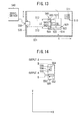
- FIG. 14 is a schematic view showing a configuration example of an origin sensor.
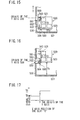
- FIG. 15 is a schematic view explaining the behavior of the apparatus of FIG. 13.
- FIG. 16 is a schematic view also explaining the behavior of the apparatus of FIG. 13.
- FIG. 17 is a graphical view also explaining the behavior of the apparatus of FIG. 13.
- FIG. 2 is a schematic diagram showing one embodiment of the present invention. Elements that are the same as those discussed in the preceding figure are given the same references.
- FIG. 2 is, more specifically, a schematic diagram showing the configuration of a servo control system.
- the platen, slider, levitating means, X-axis motors, Y-axis motor, X-axis position sensors, Y-axis position sensor, X-axis mirrors and Y-axis mirror in FIG. 2 are all similar to those in the prior art apparatus of FIG. 1.
- the X-axis position sensor 19 identifies the direction in which the slider 11 moves, and generates count-up or count-down pulses depending on the direction identified. The number of pulses generated is relative to the amount of movement made by the slider 11.
- An up-down counter 30 counts up or down according to the count-up or count-down pulses generated. The count given by the up-down counter 30 represents the detected position of the slider 11.
- the configuration of the X-axis position sensor 19 is explained later.
- Compensation means 31 contains a compensation table 32 wherein positions of the slider dependent on the curvature of mirrors are made to correspond with the amounts of correction necessary to eliminate any yawing in the slider 11.
- the compensation means 31 reads an amount of correction from the compensation table 32 according to a given directive position, and corrects the position detected by the up-down counter 30 using the amount of correction that the means has read. It should be noted here that data contained in the compensation table 32 are those obtained by means of calibration.
- the compensation means 31 is provided in order to correct curvatures in the X-axis and Y-axis mirrors 16 and 17 of FIG. 1 due to mechanical errors.
- the compensation means 31 may not be necessarily provided if the curvatures in the X-axis and Y-axis mirrors 16 and 17 are not so serious as to affect position detection.
- the X-axis position sensor 20 is also provided with an up-down counter 33, compensation means 34, and a compensation table 35.
- the converting circuit 36 receives signals for detected X-axis positions X1 and X2 from the compensation means 31 and 34, and converts these signals to signals for the X-axis position x of the center point of the slider 11 and the yaw angle ⁇ of the slider.
- An X-axis position controller 37 outputs a control signal for feedback-controlling the X-axis position of the slider 11 according to the deviation of an X-axis position command Xi from the detected position x.
- an X-axis speed-calculating circuit 38 detects the speed at which the slider 11 moves in the X-axis direction.
- the X-axis speed-calculating circuit 38 is, for example, an F/V converter.
- An X-axis speed controller 39 outputs a control signal for feedback-controlling the speed at which the slider 11 moves in the X-axis direction, according to the deviation of the control signal of the X-axis position controller 37 from a speed detected by the X-axis speed-calculating circuit 38.
- This control signal serves as a propulsion command Ir0 for moving the slider in the X-axis direction.
- the apparatus is provided with a ⁇ -axis position controller 40, ⁇ -axis speed-calculating circuit 41, and a ⁇ -axis speed controller 42, in order to control the yaw angle ⁇ .
- a control signal provided by the ⁇ -axis speed controller 42 serves as a propulsion command Ir ⁇ for rotating the slider in the ⁇ -axis direction.
- a limiter 43 restricts the X-axis limits of the propulsion command Ir0 to Imax -
- This propulsion command restricts the X-axis limits of the propulsion command Ir0 according to the magnitude of the ⁇ -axis propulsion command Ir ⁇ .
- the propulsion commands Ir1 and Ir2 will fall within the range from -Imax to +Imax by virtue of the limiter 43.
- a current sensor 45 detects an electric current that flows through the coil of the X-axis motor 14.
- a commutation and current control circuit 46 controls the commutation of the X-axis motor 14 and an electric current flowing through the coil of the X-axis motor 14.
- a commutation angle calculating circuit 47 has a sine table containing counts of the up-down counter 30 and their corresponding sine values. If a count of the up-down counter 30 is given in a case when the X-axis motor 14 is of 3-phase type, the commutation angle calculating circuit 47 reads the values of sin ⁇ and sin ( ⁇ + 120°) from the sine table.
- ⁇ is an angle that changes according to the count of the up-down counter 30.
- Multiplying digital-to-analog converters (abbreviated as MDAs) 48 and 49 output the current commands Irisin ⁇ and Ir1sin ( ⁇ + 120°), using the propulsion command Irl as an analog input signal and the values of sin ⁇ and sin ( ⁇ + 120°), which were read from the sine table, as gain-setting signals.
- MDAs digital-to-analog converters
- An X-axis current control circuit 50 controls an electric current flowing through the coil of the X-axis motor 14 according to deviations of the current commands Ir1sin ⁇ and Irlsin ( ⁇ + 120°) from currents detected by the current sensor 45.
- the X-axis motor 15 is also provided with a current sensor 51 and a commutation and current control circuit 52.
- the Y-axis servo control system is also provided with an up-down counter 53, compensation means 54, a compensation table 55, a Y-axis position controller 56, a Y-axis speed-calculating circuit 57, a Y-axis speed controller 58, and a commutation and current control circuit 59.
- control is performed without going through such a process of converting control variables as is done by the converting circuit 36.
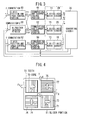
- FIG. 3 is a simplified view of the diagram of the control system shown in FIG. 2.
- the converting circuit 36 converts values X1, X2 and Y detected by the X-axis position sensor 19, X-axis position sensor 20 and Y-axis position sensor 18 to the X-axis position x of the slider 11's center point and the yaw angle ⁇ and Y-axis position Y of the slider 11.
- An X-axis position and speed controller 60 feedback-controls the X-axis position and speed of the slider 11 using the signal of position x as a feedback signal.
- the control signal of the X-axis position and speed controller 60 is output as a propulsion command Irx for the X-axis direction.
- a ⁇ -axis position and speed controller 61 feedback-controls the ⁇ -axis position and speed of the slider 11 using the signal of the yaw angle ⁇ as a feedback signal.
- the control signal of the ⁇ -axis position and speed controller 61 is output as a propulsion command Ir ⁇ for the ⁇ -axis direction.
- the propulsion commands Irx and Ir ⁇ are converted to Irx - Ir ⁇ and Irx + Ir ⁇ , i.e., the propulsion commands of the X-axis motors 14 and 15.
- control is performed separately for the X-axis and ⁇ -axis directions.
- a Y-axis position and speed controller 62 feedback-controls the Y-axis position and speed of the slider 11 using the signal of position Y as a feedback signal.
- the control signal of the Y-axis position and speed controller 62 is output as a propulsion command Iry for the Y-axis direction.
- FIG. 4 is a schematic view showing an arrangement example of motor cores present in the X-axis and Y-axis motors.
- teeth 72 and 73 are formed on the cores 70 and 71 of the X-axis motors 14 and 15, at fixed spacings along the X axis.
- the cores 70 and 71 are arranged symmetrically around the center point O of the slider 11.
- teeth 76 and 77 are formed on the cores 74 and 75 of the Y-axis motor 13, at fixed spacings along the Y axis.
- These teeth are arranged so that they are positioned opposite to the teeth of the platen 10.
- the slider 11 moves in the direction f.
- the slider 11 rotates in the direction ⁇ 1.
- the slider 11 moves in the direction g.
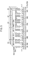
- FIG. 5 is a schematic view showing a configuration example of the motor cores present in the X-axis and Y-axis motors.
- motor cores 81 and 82 are arranged so that they sandwich permanent magnets 83.
- the permanent magnets 83 are magnetized in the direction in which the motor cores are aligned.
- the motor core 81 is provided with the windings of phase-A coils 85A, phase-B coils 85B and phase-C coils 85C, in the order in which salient poles 84A, 84B and 84C are arranged. These coils are wound so that they span their respective salient poles of the two motor cores 81 and 82.
- teeth are formed at a pitch P.
- the teeth of the salient poles 84A, 84B and 84C are given a phase shift of P/3 between each other.
- sine-wave currents with a phase shift of 120° between each other are applied to the phase-A coils 84A, phase-B coils 84B and phase-C coils 84C.
- the motor core 82 has a configuration similar to that of the motor core 81.
- the teeth of salient poles on the motor core 82 are arranged so that there is a phase shift of P/2 between them and the teeth of the motor core 81.
- the motor cores 81 and 82 move in the a-a' direction when a 3-phase sine-wave current is applied to the phase-A coils 84A, phase-B coils 84B and phase-C coils 84C.
- the motor cores shown in FIG. 5 correspond to the single core shown in FIG. 4.
- FIG. 6 is a schematic view showing a configuration example of sensors used in the apparatus of FIG. 2.
- the Y-axis position sensor 18 and X-axis position sensors 19 and 20 in FIG. 2 are all similar in their configurations.
- the X-axis position sensor 19 is taken as an example here for explanation.
- a laser light source 191 emits laser light.
- the laser light source 191 there are mirrors 192 and 193, a half mirror 194, a polarization beam splitter (abbreviated as PBS) 195, a quarter-wave plate 196, and a corner cube 197.
- PBS polarization beam splitter
- this light beam is named light beam 1 ⁇ .
- Another light beam among the light beams that have left the laser light source 191, travels along the half mirror 194, PBS 195, quarter-wave plate 196, X-axis mirror 16, quarter-wave plate 196, PBS 195, corner cube 197, quarter-wave plate 196, X-axis mirror 16, quarter-wave plate 196, PBS 195, and half mirror 194, thus also advancing in the direction b in the figure.
- this light beam is named light beam 2 ⁇ .
- the mirror 193 is arranged so that it is at an angle of 45° to the optical axis of the laser light source 191.
- the half mirror 194 is arranged so that it is at an angle of 45° + ⁇ a to the optical axis.
- the angle difference ⁇ a of the half mirror 194 causes the wavefront of the light beam 1 ⁇ to differ from that of the light beam 2 ⁇ by as much as ⁇ a.
- a photodiode array (abbreviated as PDA) 198 detects the interference fringes S.
- the PDA 198 consists of four photodiodes 198A to 198D.
- the four photodiodes 198A to 198D are placed within a single pitch of the interference fringes S.
- the photodiodes 198A to 198D are arranged at an equal spacing of p/4 (p is the pitch of the interference fringes).
- a subtractor 199 makes a calculation represented as "(signal detected by photodiode 198A) - (signal detected by photodiode 198C)."
- a subtractor 200 makes a calculation represented as "(signal detected by photodiode 198B) - (signal detected by photodiode 198D)."
- the X-axis position sensor 19 moves as the slider 11 moves, causing the interference fringes to move in the d-d' direction shown in FIG. 6.
- the light and dark bands of the interference fringes exposed to each of the photodiodes 198A to 198D also move as the interference fringes move, thus causing the values detected by the photodiode 198A to 198D to change.
- the position of the slider 11 is detected according to these changes.
- VA - VC 2mKsin ⁇ xe ⁇ 2 ⁇ /( ⁇ /4) ⁇
- VB - VD 2mKcos ⁇ xe ⁇ 2 ⁇ /( ⁇ /4) ⁇
- the signals VA - VC and VB - VD are converted to the phase-A and phase-B pulses mentioned above.
- Comparators 201 and 202 generate the phase-A and phase-B pulses from the subtraction signals of the subtractors 199 and 200.
- a direction detector 203 identifies the direction in which the slider 11 moves, in order to generate count-up or count-down pulses depending on the result of identification.
- the up-down counter 30 counts up or down according to the generated count-up or count-down pulses.
- the count of the up-down counter 30 represents the position detected by the slider 11.
- the value of the up-down counter 30 at this point is set to 0, for example, as a reference value.
- the up-down counter 30 counts up or down from the reference value as the slider 11 moves, thus detecting the position of the slider 11.
- the position of the slider 11 is detected in an incremental manner.
- FIG. 7 is a schematic view showing another configuration example of sensors used in the apparatus of FIG. 2.
- a laser light source 90 is common to the Y-axis position sensor 18 and X-axis position sensors 19 and 20.
- a Y-axis interferometer unit 91 and X-axis interferometer units 92 and 93 are units that compose the Y-axis position sensor 18 and X-axis position sensors 19 and 20, respectively.
- the Y-axis interferometer unit 91 and X-axis interferometer units 92 and 93 emit laser light in the Y-axis and X-axis directions, respectively. Then, they find positions optically by receiving light beams reflected by the Y-axis mirror 17 and X-axis mirror 16.
- the Y-axis position sensor 18 and X-axis position sensors 19 and 20 are provided with corner cubes 94, 95 and 96, respectively.
- the corner cube 94 of the Y-axis position sensor 18 is positioned at the Y-axis center point of the slider 11.
- the corner cubes 95 and 96 of the X-axis position sensors 19 and 20 are arranged symmetrically around the X-axis center line of the slider 11.
- FIG. 8 is a schematic view showing yet another configuration example of the sensors used in the apparatus of FIG. 2.
- a target mirror 301 is fixed and an optical circuit 302 moves in the h-h' direction along with the object being detected (not shown in the figure).
- a laser light source 321 emits laser light having a polarimetric component perpendicular to the plane of the sheet of paper.
- a lens 322 changes the beams of the laser light source 321 to parallel beams.
- a half mirror 323 separates light beams that have passed through the lens 322, into transmitted and reflected light beams.
- Fixed mirrors 324 and 325 receive the transmitted light beam from the half mirror 323 and reflect it back to the half mirror 323.
- the mirror 324 is arranged at an angle of 45° to the optical axis of the laser light source 321.
- the mirror 325 is arranged at an angle of 45° + ⁇ a to the optical axis.
- a polarization beam splitter (abbreviated as PBS) 326 reflects back the light beam that is reflected by the half mirror 323.
- the reflected light beam passes through a quarter-wave plate 3261 and advances to the target mirror 301.
- quarter-wave plate 3261 allows for selection from transmitted and reflected light beams with the PBS 326.
- the corner cube 327 reflects the light that has been reflected by the target mirror 301 and then transmitted through the quarter-wave plate 3261 and PBS 326, to let it go back to the PBS 326.
- a phase detector 328 detects interference fringes produced by the light that has returned to the half mirror 323.
- the distance between the target mirror 301 and the corner cube 327 is assumed to be L.
- a light beam that follows this path is named here as light beam 1 ⁇ .
- a light beam that follows this path is named here as light beam 2 ⁇ .
- the angle at which the mirror 325 is positioned is shifted by as much as ⁇ a from that of the mirror 324. Therefore, the wavefront of a light beam a that has returned after following the path of the light beam 1 ⁇ also shifts by as much as ⁇ a from that of a light beam b that has returned after following the path of the light beam 2 ⁇ .
- This wavefront shift causes light beams a1 and b1 to interfere with each other to produce interference fringes S.
- a pattern of the interference fringes S is shown in FIG. 9.
- the phase detector 328 detects interference fringes by means of a pair of photodetectors that are arranged, with a phase shift of as much as P/4 pitch from each other, in the direction in which the interference fringes are aligned.
- These photodetectors for example, are photodiodes.
- FIG. 9 shows how the two photodetectors 3281 and 3282 are arranged.
- the two photodetector 3281 and 3282 output signals corresponding to the amount of light they receive.
- Signals detected by the photodetectors 3281 and 3282 are represented as K1sin ⁇ and K1cos ⁇ (K1 is a constant and ⁇ is a phase), respectively.
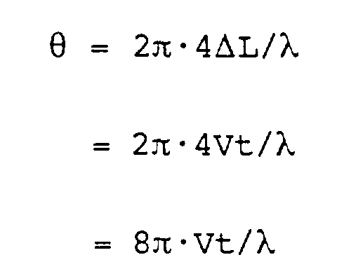
- phase ⁇ is modulated according to the amount of movement ⁇ L that the optical circuit 302 makes.
- the reason for the number "4" being present in formula (1) is because a light beam makes two round trips between the target mirror 1 and the corner cube 327; therefore, the optical length changes by as much as 4 ⁇ L when the optical circuit 2 moves by as much as ⁇ L.
- the optical circuit 302 moves at a constant speed of V along with the object being detected.
- a base clock oscillator 340 generates a base clock signal whose frequency is sufficiently higher than a frequency fc.
- An oscillator 341 generates the signal K2cos ⁇ ct (K2 is a constant; ⁇ c >> ⁇ s) from the base clock.
- a phase shifter 342 shifts the phase of the signal K2cos ⁇ ct, thereby producing the signal K2sin ⁇ ct.
- a multiplier 343 multiplies the modulated signals K1sin ⁇ st and K1cos ⁇ st by the reference signals K2cos ⁇ ct and K2sin ⁇ ct, respectively.
- An adder 344 adds the two multiplication signals to obtain the signal K1 ⁇ K2sin( ⁇ c + ⁇ s)t.
- a comparator 345 converts the addition signal to a pulse signal.
- a period counter 347 measures the period n/(fs + fc) of the frequency-divided signal received from the frequency divider 346, using the base clock. Since the frequency of the base clock is sufficiently high compared with (fc + fs)/n, it is possible to measure the period with high resolution. It should be noted that the period may be measured using a clock other than the base clock. Any measuring clock is acceptable as long as the period thereof is sufficiently short compared with the period n/(fs + fc) of the frequency-divided signal.
- a subtractor 348 finds the difference between the period n/fc of the reference signal and the measured period n/(fs + fc) of the period counter 347. This provides the period difference of nfs/fc(fs + fc).
- An integrator 349 integrates the period difference nfs/fc(fs + fc) of the subtractor 348 at intervals of n/(fs + fc). This provides the integral value fst/fc.
- a scale converter 350 multiplies the integral value fst/fc by ⁇ fc/4 to calculate the travel distance ⁇ L. From equation (3), this calculation is made as shown below: Thus, the travel distance ⁇ L can be determined.
- An arithmetic unit 351 calculates the position of an object being detected from the travel distance ⁇ L.
- the position calculation means referred to in the "What Is Claimed Is" section corresponds to the scale converter 350 and arithmetic unit 351.
- the direction in which the object being detected moves varies as the polarity of ⁇ s changes depending on the phase lead/lag relationship between the two modulated signals K1sin ⁇ st and K1cos ⁇ st; therefore, the direction is determined by judging whether the frequency fs + fc is higher or lower than fc.
- the sensors may be configured in such a manner that 1) the multiplier 343 multiplies the modulated signals Klsin ⁇ st and Klcos ⁇ st by the reference signals K2sin ⁇ ct and K2cos ⁇ ct, respectively, and 2) the adder 344 adds the two multiplication signals, thereby obtaining the signal K1 ⁇ K2cos( ⁇ c - ⁇ s)t.
- the target mirror may be made to move and the optical circuit 302 may be fixed instead.
- FIG. 10 is a schematic diagram showing a configuration example of a motor drive circuit used in the apparatus of FIG. 2.
- a motor 401 is, for example, a pulse motor.
- An current detector 402 detects the magnitude of an electric current flowing through the coil 403 of the motor 401, in an electrically isolated manner, to feed back the detected signal.
- a current error amplifier 404 calculates and amplifies the difference between a current command given by a control command and an electric current detected by a current detector 2. Thus, the current error amplifier 404 outputs the amplified signal as a voltage command.
- the calculation mentioned above is, for example, integration.
- a triangular-wave oscillator 405 generates a triangular-wave signal for producing a PWM signal (pulse-width modulated signal).
- a comparator 406 compares the voltage command signal of the current error amplifier 404 with the triangular-wave signal of the triangular-wave oscillator 405 to generate a PWM signal.
- a bridge-type inverter circuit 407 comprises two switches SW1 and SW2 connected in series, the connection point thereof being connected to the coil 403 of a motor 401 to electrify the coil 403 by turning on and off the switches SW1 and SW2.
- the switches SW1 and SW2 consist, for example, of transistors.
- Diodes D1 and D2 are connected in parallel to the switches SW1 and SW2.
- a dead-time generator 408 generates a switch control signal for turning on and off the switches SW1 and SW2 from a PWM signal supplied by a comparator 6.
- a dead time is set in the switch control signal to prevent the switches SW1 and SW2 from turning on simultaneously. If the switches SW1 and SW2 turn on simultaneously, a large current will flow through the switches, possibly burning them out.
- An isolator 409 is provided in order to isolate the inverter circuit 407 from the dead-time generator 408.
- the PWM signal output by the dead-time generator 408 is transmitted to the inverter circuit 407 in an electrically isolated manner.
- the switches SW1 and SW2 are turned on and off by the transmitted PWM signal, thus causing an electric current to flow through the coil 403.
- the output voltage of the inverter circuit 407 is a rectangular-wave signal and the voltage's mean value is proportional to the output of the current error amplifier 404.
- the output voltage of the inverter circuit 407 turns on an electric current through the motor 401 and an electric current feedback signal is obtained by means of the current detector 402 to form a feedback loop and thereby a constant-current loop.
- a voltage detector 420 detects the output voltage of the inverter circuit 407 and is, for example, an electrically isolated voltage detector.
- An LPF (low-pass filter) 421 cuts off PWM noise contained in the output of the voltage detector 420 included to obtain a voltage feedback signal.
- a voltage error amplifier 422 amplifies the difference between a voltage command given by the voltage command signal of the current error amplifier 404 and a voltage value detected by the voltage detector 420. Thus, the voltage error amplifier 422 outputs the amplified signal as a voltage compensation signal.
- An adder 423 adds the voltage compensation signal to the voltage command signal to compensate the voltage command signal. Then, the adder 423 feeds the compensated voltage command signal to the comparator 406. The addition signal is compared with a triangular-wave signal of the triangular-wave oscillator 405 to generate a PWM signal.
- the output voltage of the inverter circuit 407 is fed back, a voltage compensation signal is produced from the signal thus fed back, and a voltage command signal is compensated by the voltage compensation signal. Consequently, it is possible to reduce errors that may occur due to a deadband in the output voltage of the inverter circuit 407 when the direction of electric current is changed.
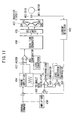
- FIG. 11 is a schematic diagram showing another configuration example of the motor drive circuit used in the apparatus of FIG. 2.
- An amplifier 430 amplifies a current command signal given by the control command.
- An adder 431 adds the amplified signal of the amplifier 430 and the current feedback signal of the current detector 402 to produce a monitor signal. This addition is performed to take an average of the two signals.
- a comparator 432 compares the level of the monitor signal with a given reference value to detect the direction (polarity) of electric current.
- the comparator 432 is a hysteresis-based comparator.
- a level converter 433 sets the output of the comparator 432 to a level for detecting a zero-cross point corresponding to the direction of electric current.
- a comparator 434 compares the level of the monitor signal with the level set by the level converter 433 to detect a zero-cross point corresponding to the direction of electric current.
- the direction of electric current referred to here is either the case when the current changes from the positive to negative polarity or the case when the current changes from the negative to positive polarity.
- a synchronizer 435 synchronizes the output of the comparator 434 with the triangular-wave signal of the triangular-wave oscillator 405.
- the synchronizer 435 is composed of flip-flops.
- the monitor signal Since the current feedback signal output by the current detector 402 has a lag against the control command, the monitor signal has a phase lead against an actual electric current of the coil 403. This phase lead is determined by the gain of the amplifier 430. The gain of the amplifier 430 is adjusted properly to produce the optimum timing for compensating a deadband near a zero-cross point.
- the reference input with which the compensation of a deadband near a zero-cross point begins is adjusted to the optimum level by adjusting the level of the level converter 433.
- the output of the comparator 434 is synchronized with a triangular-wave signal by the synchronizer 435, and then input to the level converter 436.
- the level converter 436 is set to a level for compensating the output voltage of the inverter circuit 407 near a zero-cross point.
- the level converter 436 produces a signal adjusted so as to compensate a change in the duty ratio of the output signal of the inverter circuit 407.
- An adder 437 adds the output signal of the level converter 436 to the voltage command signal of the current error amplifier 404 to compensate the voltage command. Consequently, any change in the duty ratio of the output signal of the inverter circuit 407 is cancelled and, therefore, any dead-time distortion is compensated.
- FIG. 12 is a timing chart showing the relationship among signals in the circuit diagram of FIG. 11.
- a current command signal B1 and the output current B2 of the inverter circuit 407 are added to produce an addition signal B3.
- the addition signal B3 is input into the comparators 432 and 434.
- the output B5 of the comparator 432 is changed to a different level by the level converter 433 to be given as a reference level B6 to the comparator 434.
- the output B7 of the comparator 434 changes.
- the output B7 of the comparator 434 is synchronized with the synchronization clock of the synchronizer 435.
- the level of the output B7 is changed by the level converter 436 to become an output B8.
- the average of the voltage command is negative, as indicated by a symbol B9.
- the output B8 and voltage command B9 are added by an adder 437, and the output B10 thereof is given to the comparator 406 after correction.
- the pulse width of a PWM signal shortens after the post-correction output B10 has risen. Consequently, a deadband near a zero-cross point in the output current of the inverter circuit 407 is cancelled.
- the motor 401 may be a direct drive motor or a linear motor.
- the motor 401 may also be a motor for moving the slider of the two-dimensional positioning apparatus in which the slider is levitated by means of air bearings.
- position measurement is performed by means of laser light interference.
- the wavelength of laser light can change due to, for example, aging.
- Means for measuring laser light wavelengths is therefore provided in the apparatus in order to detect such a change.
- FIG. 13 is a schematic view showing a configuration example of a two-dimensional positioning apparatus provided with means for measuring laser light wavelengths.
- the two-dimensional positioning apparatus comprises:
- the slider 520 comprises means for levitating the slider 520 by means of an air bearings mechanism (not shown in the figure); rotors consisting of cores and coils for moving the slider 520 in the X-axis and Y-axis directions by means of magnetic attraction (not shown in the figure); and a slit temperature sensor 570 for detecting the temperature of a return-to-origin slit plate 560.
- the upper section of the slider 520 comprises X1-axis and X2-axis laser interferometers 521 and 522 for emitting the laser light 512 and 513 onto the X-axis mirror 530 to detect the X-axis position by means of the interference between catoptric light beams from the X-axis mirror 530; a Y-axis laser interferometer 523 for emitting the laser light 514 onto the Y-axis mirror 531 to detect the Y-axis position by means of the interference between catoptric light beams from the Y-axis mirror 531; and a return-to-origin slit plate 560 located on the X axis of the slider 520.
- the X1-axis and X2-axis laser interferometers 521 and 522 are arranged at a given spacing so as to detect the yaw angle (rotational angle ⁇ around the Z axis) of the slider 520.
- the return-to-origin slit plate 560 is formed using glass slits and comprises two X1 and X2 slits 561 and 562 separately aligned in series in the Y-axis direction; a Y slit 563 positioned external and perpendicular to the X1 slit 561; and a wavelength-calibrating C slit 564 positioned external and perpendicular to the X2 slit 562.
- the wavelength-calibrating C slit 564 is formed so as to be parallel and share the same width with the Y slit 563.
- the Y slit 563 and wavelength-calibrating C slit 564 compose the means for detecting laser wavelengths.
- the origin sensor 550 comprises a light emitter for emitting light consisting of laser lights; a Y-axis photodetector 553 consisting of two photodetectors 551 and 552 arranged at a given spacing; and an X-axis photodetector 556 consisting of two photodetectors 554 and 555 arranged in the direction perpendicular to the Y-axis photodetector 553.
- the slider 520 can move above the platen 510 by means of magnetic attraction. Additionally, the servo driver 540 connected to the slider 520 performs positioning control using position signals provided by the X1-axis and X2-axis laser interferometers 521 and 522 and Y-axis laser interferometer 523 on the slider 520.
- the servo driver 540 controls the X-axis position and the rotational angle ⁇ of the slider 520 provided by the interference between catoptric light beams 512 and 513 from the X1-axis and X2-axis laser interferometers 521 and 522 fixed onto the slider 520, and detects the Y-axis position provided by the interference between the catoptric beams of the laser light 514 emitted by the Y-axis laser interferometer 523.
- the return-to-origin slit plate 560 located on the X axis of the slider 520 is aligned with the origin sensor 550 located at the X-axis end of the platen 510 in order to cause return-to-origin action in the X-axis, Y-axis and ⁇ -axis directions.
- the on-off state of a Y-axis origin signal changes, as shown in FIG. 17, when as shown in FIG. 15, the Y slit 563 reaches the Y-axis origin position where the Y-axis photodetector 553 of the origin sensor 550 is located.
- This enables the servo driver 540 to place the slider 520 in a Y-axis position where the Y slit 563 agrees with the Y-axis origin position.
- the coefficient (number of detected interference fringes), which is provided at this point by the interference between the catoptric beams of the laser light 514 emitted by the Y-axis laser interferometer 523 and indicates the detected Y-axis position, is assumed to be Yo.
- the slider 520 is moved in parallel with the X-axis mirror 530 to position the slider 520 so that the C slit 564 agrees with the Y-axis origin position.
- the coefficient (number of detected interference fringes), which is provided at this point by the interference between the catoptric beams of the laser light 514 emitted by the Y-axis laser interferometer 523 and indicates the detected Y-axis position, is assumed to be Yc.
- Equation (4) is the means for measuring the wavelength of the laser light 514 from the interference between the catoptric beams of the laser light 514, where the interference occurs at the origin position that is detected by each of the two slits (Y and C slits 563 and 564) using the same photodetector (Y origin position (556) of the origin sensor 550).
- position detection based on the Y and C slits 563 and 564 using the same origin sensor 550 is performed by moving the slider 520 in the Y-axis direction, thus calculating the distance-related coefficients Yo and Yc.
- the laser light wavelength ⁇ n is calculated according to equation (4) so that deterioration in the laser light can be measured each time return-to-origin action takes place.
- the return-to-origin slit plate 560 expands or contracts slightly depending on the temperature.
- the length of expansion or contraction can be corrected, however, using the temperature detected by the slit temperature sensor and therefore can be taken into account.
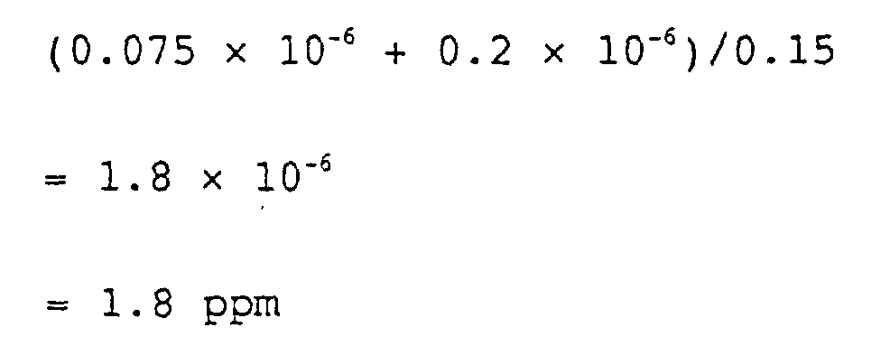
- the linear expansion factor of the return-to-origin slit plate 560 is 0.5 ⁇ 10 -6
- the reproduction accuracy of the origin signal of the origin sensor 550 is ⁇ 0.1 ⁇ m
- the temperature error occurring in (Yc-Yo) is ⁇ 0.2 ⁇ m. Therefore, the accuracy with which the laser light wavelength ⁇ n is detected is approximately This means the position detection error occurring when the distance of the X1-axis and X2-axis laser interferometers 521 and 522 from the X-axis mirror 530 is 1 m is kept to approximately 2 ⁇ m.
- the distance of the C slit 564 from the Y slit 563 can be made as long as possible in this embodiment, while maintaining the positional relationship between the Y and C slits 563 and 564 to be the same. Consequently, it becomes possible to detect deterioration in the laser light of a laser interferometer at an early stage by simply measuring an error between the detection accuracy of the Y slit 563 and that of the wavelength-calibrating C slit 564.
- the two slits at the moment of returning to the origin are used to measure the wavelength of laser light from the difference in the interference between the catoptric beams of laser light that is emitted from different positions of the slider 520. Consequently, the apparatus is advantageous in that it is possible to detect deterioration in laser light due to aging at an early stage and maintain the high accuracy of slider positioning.
Landscapes
- Physics & Mathematics (AREA)
- General Physics & Mathematics (AREA)
- Engineering & Computer Science (AREA)
- Human Computer Interaction (AREA)
- Manufacturing & Machinery (AREA)
- Automation & Control Theory (AREA)
- Chemical & Material Sciences (AREA)
- Combustion & Propulsion (AREA)
- Electromagnetism (AREA)
- Power Engineering (AREA)
- Length Measuring Devices By Optical Means (AREA)
- Control Of Position Or Direction (AREA)
Abstract
Description

Claims (20)
- A two-dimensional positioning apparatus for positioning an object in a two-dimensional direction, comprising:a platen whereon teeth are formed at fixed spacings along the X and Y axes;a slider provided with two X-axis motors, two X-axis position sensors, a Y-axis motor and a Y-axis position sensor, said slider being loaded with said object and levitated above said platen;a converter for producing signals for detecting the X-axis position of said slider's center point and the yaw angle of said slider according to the position detection signals of said two X-axis position sensors;an x controller for feedback-controlling the movement of said slider in the X-axis and -axis directions separately according to signals converted by said converter;a command converting circuit for converting the control output of said X controller to propulsion commands to be given to said two X-axis motors; anda Y-axis controller for receiving the position detection signal of said Y-axis position sensor and feedback-controlling the Y-axis direction according to said position detection signal.
- A two-dimensional positioning apparatus for positioning an object in a two-dimensional direction, comprising:a platen whereon teeth are formed at fixed spacings along the X and Y axes;a slider loaded with said object;levitating means for levitating said slider above said platen;a Y-axis motor mounted on said slider to move said slider in the Y-axis direction;first and second X-axis motors mounted symmetrically around the center point of said slider to move said slider in the X-axis direction;a Y-axis position sensor for detecting the Y-axis position of said slider;first and second X-axis position sensors mounted on said first and second X-axis motors, respectively, to detect the respective X-axis positions of said slider;a converter for receiving the position detection signals of said first and second X-axis position sensors, producing a signal for detecting the X-axis position of said slider's center point according to the sum of said position detection signals, and producing a signal for detecting the yaw angle of said slider according to the difference between said position detection signals;an X controller for feedback-controlling the movement of said slider in the X-axis and -axis directions separately according to signals converted by said converter;a command converting circuit for converting X-axis and 6-axis propulsion commands, which are the control outputs of said X controller, to propulsion commands to be given to said two X-axis motors; anda Y-axis controller for receiving the position detection signal of said Y-axis position sensor and feedback-controlling the Y-axis direction according to said position detection signal.
- The two-dimensional positioning apparatus of claim 2, wherein said command converting circuit receives X-axis and -axis propulsion commands output by said X controller to produce propulsion commands to be given to said two X-axis motors according to the sum of and difference between said X-axis and -axis propulsion commands.
- The two-dimensional positioning apparatus of claim 2, further comprising a limiter for restricting the X-axis limits of the propulsion command Ir0 to Imax - |Ir| (Imax is the maximum value of the propulsion command and Ir is a -axis propulsion command) and thereby restricting the limits of the propulsion command Ir0 according to the magnitude of the -axis propulsion command Ir.
- The two-dimensional positioning apparatus of claim 2, wherein said first and second X-axis motors have cores whereon teeth are formed opposite to the teeth of said platen at fixed spacings along the X axis, the cores of said first and second X-axis motors being arranged symmetrically around the center point of said slider.
- The two-dimensional positioning apparatus of claim 2, wherein said Y-axis position sensor and said first and second X-axis position sensors optically detect position using laser interferometers and are provided with corner cubes, the corner cube of said Y-axis position sensor being arranged at the center point of the Y axis and the corner cubes of said first and second X-axis position sensors being arranged symmetrically around the X-axis center line of said slider.
- A two-dimensional positioning apparatus, comprising:wherein said two-dimensional positioning apparatus further comprises:an optical circuit for producing interference fringes with a fixed pitch, by means of optical interference, that move as an object being detected moves; anda position sensor having a phase detector for detecting interference fringes by means of a plurality of photodetectors arranged at a given spacing in the direction in which the interference fringes are aligned and producing two modulated signals that are modulated according to the amount of movement made by said object,a multiplier for multiplying said two modulated signals by reference signals generated from a base clock; andan adder for adding said two multiplication signals.
- A two-dimensional positioning apparatus having position sensors for optically detecting the position of an object being detected using interferometers, comprising:an optical circuit for producing interference fringes with a pitch P, by means of optical interference, that move as said object moves;a phase detector for detecting interference fringes by means of a plurality of photodetectors that are arranged with a phase shift of as much as P/4 pitch from each other, in the direction in which the interference fringes are aligned, and producing the modulated signals K1sinωst and K1cosωst (K1 is a constant and t is time), whose angular frequency ωs is modulated according to the amount of movement made by said object, from signals detected by said plurality of photodetectors;a multiplier for multiplying said modulated signals K1sinωst and K1cosωst by the reference signals K2cosωct and K2sinωct (ωc >> ωs), respectively, that are generated from a base clock;an adder for adding said two multiplication signals to obtain the signal K1·K2sin(ωc + ωs)t;a comparator for converting said addition signal to a pulse signal;a frequency divider for dividing said pulse signal with a dividing ratio of n (n is an integer);a period counter for measuring the period n/(fs + fc) (ωc = 2πfc and ωs = 2πfs) of a frequency-divided signal obtained from said frequency divider by using a clock which is synchronized with said base clock and whose period is sufficiently short compared with the period of said frequency-divided signal;a subtractor for finding the difference between the measured period of said period counter and the period n/fc of a reference signal;an integrator for integrating the period difference of said subtractor at intervals of n/(fs + fc); andposition calculation means for calculating the position of said object from the integrated value of said integrator.
- The two-dimensional positioning apparatus of claim 8, further comprising:wherein the signals K2cosωct and K2sinωct generated by said phase shifter are supplied to said multiplier and said base clock is supplied to said period counter as a period-measuring clock.a base clock oscillator for generating a base clock whose frequency is higher than the frequency fc;an oscillator for generating the signal K2cosωct or K2sinωct from said base clock; anda phase shifter for shifting the phase of the signal generated by said oscillator, thereby producing the signals K2cosωct and K2sinωct,
- The two-dimensional positioning apparatus of claim 8, wherein said multiplier multiplies the modulated signals K1sinωst and K1cosωst by the reference signals K2sinωct and K2cosωct, respectively, and said adder adds the two multiplication signals to obtain the signal K1·K2cos(ωc - ωs)t.
- A two-dimensional positioning apparatus having a motor drive circuit which includes:wherein said two-dimensional positioning apparatus further comprises a voltage detector for detecting the output voltage of said inverter circuit, thereby adding the voltage feedback signal of said voltage detector to said current error signal.a bridge-type inverter circuit for turning on electric current through the coil of a motor;a current detector for detecting the magnitude of electric current flowing through the coil of said motor;a PWM circuit for generating a PWM signal corresponding to a current error signal representing a difference between a current command and an electric current detected by said current sensor;
anda dead-time generator to which said PWM signal is input in order to supply a switch control signal to said inverter circuit, - A two-dimensional positioning apparatus having a motor drive circuit which includes:wherein said two-dimensional positioning apparatus further comprises:a current detector for detecting the magnitude of electric current flowing through the coil of a motor;a bridge-type inverter circuit having two switches connected in series, the connection point thereof being connected to the coil of said motor to electrify the coil by turning on and off said two switches;a current error amplifier for calculating and amplifying the difference between a current command given by a control command and an electric current detected by said current detector, thus outputting the amplified signal as a voltage command signal;a PWM circuit for generating a PWM signal by comparing said voltage command signal with a given ac signal;a dead-time generator for generating a switch control signal, wherein a dead time is set to prevent said two switches from turning on simultaneously, from said PWM signal, and then supplying said switch control signal to said inverter circuit;a voltage detector for detecting the output voltage of said inverter circuit;a voltage error amplifier for amplifying the difference between a voltage command given by said voltage command signal and a voltage detected by said voltage detector, thus outputting the amplified signal as a voltage compensation signal; andan adder for adding said voltage compensation signal to said voltage command signal to compensate said voltage command signal and feeding the compensated voltage command signal to said PWM circuit.
- A two-dimensional positioning apparatus having a motor drive circuit which includes:wherein said two-dimensional positioning apparatus further comprises:a current detector for detecting the magnitude of electric current flowing through the coil of a motor;a bridge-type inverter circuit having two switches connected in series, the connection point thereof being connected to the coil of said motor to electrify the coil by turning on and off said two switches;a current error amplifier for calculating and amplifying the difference between a current command given by a control command and an electric current detected by said current detector, thus outputting the amplified signal as a voltage command signal;a PWM circuit for generating a PWM signal by comparing said voltage command signal with a given ac signal;a dead-time generator for generating a switch control signal, wherein a dead time is set to prevent said two switches from turning on simultaneously, from said PWM signal, and then supplying said switch control signal to said inverter circuit;an adder for adding said voltage command and a signal detected by said current detector;a first comparator having hysteresis that compares the addition signal level of said adder with a given reference value to detect the direction of electric current;a first level converter for setting the output of said first comparator to a level for detecting a zero-cross point corresponding to the direction of electric current.a second comparator for comparing the addition signal level of said adder with the level set by said first level converter to detect a zero-cross point corresponding to the direction of electric current;a synchronizer for synchronizing the output of said second comparator with said given ac signal;a second level converter for setting the signal synchronized by said synchronizer to such a level as to compensate a change in the duty ratio of the output signal of said inverter circuit; andan adder for adding the signal converted by said second level converter to said voltage command signal to compensate said voltage command signal and supplying the compensated voltage command signal to said PWM circuit.
- A two-dimensional positioning apparatus, comprising:a platen whereon teeth are formed at fixed spacings along the X and Y axes;a slider capable of levitating above said platen and moving in the X-axis and Y-axis directions by means of magnetic attraction, while positioning itself by means of the interference between the catoptric beams of laser light;means for detecting the origin position by means of at least two mutually parallel slits of the same width formed on said slider; andmeans for measuring the wavelength of laser light by means of the difference in the interference between the catoptric beams of said laser light at the origin position that is detected by each of said two slits using the same photodiode;
- The two-dimensional positioning apparatus of claim 14, wherein said two slits are located on a return-to-origin slit plate that is used when returning said slider to a given position on said platen.
- The two-dimensional positioning apparatus of claim 15, wherein said return-to-origin slit plate comprises:two slits X1 and X2 separately aligned in series in the Y-axis direction;a Y slit positioned perpendicular to said two slits X1 and X2; anda wavelength-calibrating C slit formed so as to be parallel and share the same width with said Y slit.
- The two-dimensional positioning apparatus of claim 16, wherein the positional relationship of slits formed on said return-to-origin slit plate is such that said Y slit is located so as to be external and perpendicular to said X1 slit and said wavelength-calibrating C slit is located so as to be also external and perpendicular to said X2 slit.
- The two-dimensional positioning apparatus of claim 15, wherein said slider is provided with a temperature sensor for sensing the temperature of said return-to-origin slit plate to correct signals detected by said two slits according to a signal detected by said temperature sensor.
- A method for measuring the laser light of a two-dimensional positioning apparatus, wherein a slider that emits laser light in the X-axis and Y-axis directions, moves while positioning itself by means of an interference between the catoptric beams of the emitted laser light, and takes return-to-origin action by using the slits of a return-to-origin slit plate, is employed in said two-dimensional positioning apparatus, said return-to-origin slit plate having at least two mutually parallel slits of the same width, whereby the wavelength of laser light is measured from the difference in the interference between the catoptric beams of laser light coming from the origin position that is detected by each of said two slits using the same photodiode.
- The method of claim 19, wherein one of said two slits is a Y slit for determining the Y-axis origin position of said slider and the other is a wavelength-calibrating C slit.
Applications Claiming Priority (8)
| Application Number | Priority Date | Filing Date | Title |
|---|---|---|---|
| JP30879799A JP3543701B2 (en) | 1999-10-29 | 1999-10-29 | 2D positioning device |
| JP30879799 | 1999-10-29 | ||
| JP33148099 | 1999-11-22 | ||
| JP33148099A JP3512072B2 (en) | 1999-11-22 | 1999-11-22 | Position detection device |
| JP33465399A JP3541382B2 (en) | 1999-11-25 | 1999-11-25 | X / Y stage laser beam measuring method and X / Y stage |
| JP33465399 | 1999-11-25 | ||
| JP33838399 | 1999-11-29 | ||
| JP33838399A JP3458378B2 (en) | 1999-11-29 | 1999-11-29 | Motor drive circuit |
Publications (2)
| Publication Number | Publication Date |
|---|---|
| EP1111489A1 true EP1111489A1 (en) | 2001-06-27 |
| EP1111489B1 EP1111489B1 (en) | 2003-10-22 |
Family
ID=27479980
Family Applications (1)
| Application Number | Title | Priority Date | Filing Date |
|---|---|---|---|
| EP00123536A Expired - Lifetime EP1111489B1 (en) | 1999-10-29 | 2000-10-27 | Two-dimensional positioning apparatus and method for measuring laser light from the apparatus |
Country Status (3)
| Country | Link |
|---|---|
| US (1) | US6603562B1 (en) |
| EP (1) | EP1111489B1 (en) |
| DE (1) | DE60006060T2 (en) |
Cited By (2)
| Publication number | Priority date | Publication date | Assignee | Title |
|---|---|---|---|---|
| CN1306241C (en) * | 2004-02-20 | 2007-03-21 | 安捷伦科技有限公司 | System and method of using a side-mounted interferometer to acquire position information |
| EP1852763A4 (en) * | 2005-02-18 | 2010-10-06 | Yokogawa Electric Corp | XY FLOOR |
Families Citing this family (2)
| Publication number | Priority date | Publication date | Assignee | Title |
|---|---|---|---|---|
| US10033309B2 (en) * | 2015-07-17 | 2018-07-24 | Anpec Electronics Corporation | Control apparatus for dynamically adjusting phase switching of the DC motor and method thereof |
| RU2663542C1 (en) * | 2017-06-07 | 2018-08-07 | Анатолий Борисович Попов | Interferometer of absolute gravimeter |
Citations (8)
| Publication number | Priority date | Publication date | Assignee | Title |
|---|---|---|---|---|
| US4657392A (en) * | 1982-08-05 | 1987-04-14 | Honeywell Inc. | Lock-in rate discriminate apparatus for ring laser angular rate sensors |
| US4719400A (en) * | 1982-10-19 | 1988-01-12 | Fanuc Ltd. | Motor control apparatus |
| EP0533403A2 (en) * | 1991-09-17 | 1993-03-24 | Otis Elevator Company | Blanking interval voltage deviation compensator for inverters and converters |
| EP0637870A1 (en) * | 1992-07-21 | 1995-02-08 | Kabushiki Kaisha Meidensha | Vector control apparatus for induction motor |
| US5450195A (en) * | 1993-03-05 | 1995-09-12 | Jenoptik Gmbh | Phase-modulated interferometer for evaluating phase displacement resulting from charges in path length |
| US5585683A (en) * | 1990-04-16 | 1996-12-17 | Fujitsu Limited | Electrostatic actuators of various configuration with belt-like electrodes to induce an image charge on a resistance member and cause relative motion |
| EP0911952A2 (en) * | 1997-10-27 | 1999-04-28 | Hewlett-Packard Company | Electrostatic actuator |
| WO1999042785A2 (en) * | 1998-02-23 | 1999-08-26 | Zygo Corporation | Apparatus and method for measuring the refractive index and optical path length effects of air using multiple-pass interferometry |
Family Cites Families (9)
| Publication number | Priority date | Publication date | Assignee | Title |
|---|---|---|---|---|
| FR2088675A5 (en) * | 1970-04-21 | 1972-01-07 | Thomson Csf | |
| JPS63242187A (en) * | 1987-03-27 | 1988-10-07 | Yokogawa Electric Corp | Controller for motor |
| JP2816015B2 (en) * | 1990-10-30 | 1998-10-27 | 横河プレシジョン株式会社 | Linear optical encoder |
| US5506684A (en) * | 1991-04-04 | 1996-04-09 | Nikon Corporation | Projection scanning exposure apparatus with synchronous mask/wafer alignment system |
| JP3448991B2 (en) * | 1994-11-29 | 2003-09-22 | 株式会社ニコン | Stage movement control device, projection exposure apparatus, stage driving method, and exposure method. |
| US5552888A (en) * | 1994-12-02 | 1996-09-03 | Nikon Precision, Inc. | Apparatus for measuring position of an X-Y stage |
| JPH08227839A (en) * | 1995-02-20 | 1996-09-03 | Nikon Corp | Moving mirror bending measurement method |
| EP1028456A4 (en) * | 1997-09-19 | 2003-03-05 | Nikon Corp | PLATINUM, SCANNING ALIGNMENT DEVICE, AND SCANNING EXPOSURE METHOD, AND DEVICE MANUFACTURED THEREBY |
| JP3630964B2 (en) * | 1997-12-26 | 2005-03-23 | キヤノン株式会社 | Stage apparatus, exposure apparatus using the same, and device manufacturing method |
-
2000
- 2000-10-21 US US09/692,960 patent/US6603562B1/en not_active Expired - Fee Related
- 2000-10-27 EP EP00123536A patent/EP1111489B1/en not_active Expired - Lifetime
- 2000-10-27 DE DE60006060T patent/DE60006060T2/en not_active Expired - Lifetime
Patent Citations (8)
| Publication number | Priority date | Publication date | Assignee | Title |
|---|---|---|---|---|
| US4657392A (en) * | 1982-08-05 | 1987-04-14 | Honeywell Inc. | Lock-in rate discriminate apparatus for ring laser angular rate sensors |
| US4719400A (en) * | 1982-10-19 | 1988-01-12 | Fanuc Ltd. | Motor control apparatus |
| US5585683A (en) * | 1990-04-16 | 1996-12-17 | Fujitsu Limited | Electrostatic actuators of various configuration with belt-like electrodes to induce an image charge on a resistance member and cause relative motion |
| EP0533403A2 (en) * | 1991-09-17 | 1993-03-24 | Otis Elevator Company | Blanking interval voltage deviation compensator for inverters and converters |
| EP0637870A1 (en) * | 1992-07-21 | 1995-02-08 | Kabushiki Kaisha Meidensha | Vector control apparatus for induction motor |
| US5450195A (en) * | 1993-03-05 | 1995-09-12 | Jenoptik Gmbh | Phase-modulated interferometer for evaluating phase displacement resulting from charges in path length |
| EP0911952A2 (en) * | 1997-10-27 | 1999-04-28 | Hewlett-Packard Company | Electrostatic actuator |
| WO1999042785A2 (en) * | 1998-02-23 | 1999-08-26 | Zygo Corporation | Apparatus and method for measuring the refractive index and optical path length effects of air using multiple-pass interferometry |
Cited By (2)
| Publication number | Priority date | Publication date | Assignee | Title |
|---|---|---|---|---|
| CN1306241C (en) * | 2004-02-20 | 2007-03-21 | 安捷伦科技有限公司 | System and method of using a side-mounted interferometer to acquire position information |
| EP1852763A4 (en) * | 2005-02-18 | 2010-10-06 | Yokogawa Electric Corp | XY FLOOR |
Also Published As
| Publication number | Publication date |
|---|---|
| DE60006060D1 (en) | 2003-11-27 |
| US6603562B1 (en) | 2003-08-05 |
| EP1111489B1 (en) | 2003-10-22 |
| DE60006060T2 (en) | 2004-07-22 |
Similar Documents
| Publication | Publication Date | Title |
|---|---|---|
| US4193693A (en) | Velocity servo for continuous scan Fourier interference spectrometer | |
| CN102192784B (en) | Interferometer step scanning system and method | |
| KR0138337B1 (en) | Focus control method and apparatus | |
| JP2014032105A (en) | Measurement device, lithography device, and article manufacturing method | |
| CN114396928A (en) | Laser gyro frequency stabilization method and system | |
| EP0795115A2 (en) | System and method for measuring angular position | |
| EP1111489B1 (en) | Two-dimensional positioning apparatus and method for measuring laser light from the apparatus | |
| US11695354B2 (en) | Motor control apparatus, optical apparatus, and robot manipulator apparatus | |
| US7425783B2 (en) | Linear motor | |
| KR100915163B1 (en) | Xy stage | |
| JP3543701B2 (en) | 2D positioning device | |
| JP3834433B2 (en) | XY stage | |
| US5268740A (en) | Fiber optic Sagnac interferometer with carrier frequency reduced output for measuring a rate of rotation | |
| EP0364984A2 (en) | Interferometer using multi-mode semiconductor laser | |
| JP4595554B2 (en) | Planar motor | |
| JP2005009952A (en) | XY stage | |
| JPS63203917A (en) | Magnetic levitation linear bearing | |
| JPS5845630A (en) | Relative position controller in track orthogonal direction for recording track and pickup in information reader | |
| JPS61274205A (en) | Optical displacement measuring device | |
| JPH0638294B2 (en) | Optical disk tracking controller | |
| JPS6293603A (en) | Optical physical quantity measuring device | |
| JP2001154737A (en) | Positioning device and its origin return method | |
| JP2003250295A (en) | Positioning device | |
| JP2005284867A (en) | Drive control apparatus and method, and exposure apparatus | |
| Suzuki et al. | Coaxial type of self-mixing interferometer equipped with a wavelength stabilizing system |
Legal Events
| Date | Code | Title | Description |
|---|---|---|---|
| PUAI | Public reference made under article 153(3) epc to a published international application that has entered the european phase |
Free format text: ORIGINAL CODE: 0009012 |
|
| AK | Designated contracting states |
Kind code of ref document: A1 Designated state(s): DE GB |
|
| AX | Request for extension of the european patent |
Free format text: AL;LT;LV;MK;RO;SI |
|
| 17P | Request for examination filed |
Effective date: 20011219 |
|
| AKX | Designation fees paid |
Free format text: DE GB |
|
| 17Q | First examination report despatched |
Effective date: 20020219 |
|
| GRAH | Despatch of communication of intention to grant a patent |
Free format text: ORIGINAL CODE: EPIDOS IGRA |
|
| GRAS | Grant fee paid |
Free format text: ORIGINAL CODE: EPIDOSNIGR3 |
|
| GRAA | (expected) grant |
Free format text: ORIGINAL CODE: 0009210 |
|
| AK | Designated contracting states |
Kind code of ref document: B1 Designated state(s): DE GB |
|
| REG | Reference to a national code |
Ref country code: GB Ref legal event code: FG4D |
|
| REF | Corresponds to: |
Ref document number: 60006060 Country of ref document: DE Date of ref document: 20031127 Kind code of ref document: P |
|
| PLBE | No opposition filed within time limit |
Free format text: ORIGINAL CODE: 0009261 |
|
| STAA | Information on the status of an ep patent application or granted ep patent |
Free format text: STATUS: NO OPPOSITION FILED WITHIN TIME LIMIT |
|
| 26N | No opposition filed |
Effective date: 20040723 |
|
| PGFP | Annual fee paid to national office [announced via postgrant information from national office to epo] |
Ref country code: GB Payment date: 20101027 Year of fee payment: 11 |
|
| GBPC | Gb: european patent ceased through non-payment of renewal fee |
Effective date: 20121027 |
|
| PG25 | Lapsed in a contracting state [announced via postgrant information from national office to epo] |
Ref country code: GB Free format text: LAPSE BECAUSE OF NON-PAYMENT OF DUE FEES Effective date: 20121027 |
|
| PGFP | Annual fee paid to national office [announced via postgrant information from national office to epo] |
Ref country code: DE Payment date: 20131023 Year of fee payment: 14 |
|
| REG | Reference to a national code |
Ref country code: DE Ref legal event code: R119 Ref document number: 60006060 Country of ref document: DE |
|
| PG25 | Lapsed in a contracting state [announced via postgrant information from national office to epo] |
Ref country code: DE Free format text: LAPSE BECAUSE OF NON-PAYMENT OF DUE FEES Effective date: 20150501 |