EP1111488A2 - Camera for a vehicle - Google Patents
Camera for a vehicle Download PDFInfo
- Publication number
- EP1111488A2 EP1111488A2 EP00125844A EP00125844A EP1111488A2 EP 1111488 A2 EP1111488 A2 EP 1111488A2 EP 00125844 A EP00125844 A EP 00125844A EP 00125844 A EP00125844 A EP 00125844A EP 1111488 A2 EP1111488 A2 EP 1111488A2
- Authority
- EP
- European Patent Office
- Prior art keywords
- camera
- vehicle
- screen
- image
- reference mark
- Prior art date
- Legal status (The legal status is an assumption and is not a legal conclusion. Google has not performed a legal analysis and makes no representation as to the accuracy of the status listed.)
- Granted
Links
- 238000006073 displacement reaction Methods 0.000 description 3
- 238000011156 evaluation Methods 0.000 description 3
- 238000000034 method Methods 0.000 description 3
- 238000010586 diagram Methods 0.000 description 2
- 230000004297 night vision Effects 0.000 description 1
- 230000000007 visual effect Effects 0.000 description 1
Images
Classifications
-
- B—PERFORMING OPERATIONS; TRANSPORTING
- B60—VEHICLES IN GENERAL
- B60R—VEHICLES, VEHICLE FITTINGS, OR VEHICLE PARTS, NOT OTHERWISE PROVIDED FOR
- B60R1/00—Optical viewing arrangements; Real-time viewing arrangements for drivers or passengers using optical image capturing systems, e.g. cameras or video systems specially adapted for use in or on vehicles
- B60R1/20—Real-time viewing arrangements for drivers or passengers using optical image capturing systems, e.g. cameras or video systems specially adapted for use in or on vehicles
- B60R1/22—Real-time viewing arrangements for drivers or passengers using optical image capturing systems, e.g. cameras or video systems specially adapted for use in or on vehicles for viewing an area outside the vehicle, e.g. the exterior of the vehicle
- B60R1/28—Real-time viewing arrangements for drivers or passengers using optical image capturing systems, e.g. cameras or video systems specially adapted for use in or on vehicles for viewing an area outside the vehicle, e.g. the exterior of the vehicle with an adjustable field of view
-
- B—PERFORMING OPERATIONS; TRANSPORTING
- B60—VEHICLES IN GENERAL
- B60R—VEHICLES, VEHICLE FITTINGS, OR VEHICLE PARTS, NOT OTHERWISE PROVIDED FOR
- B60R1/00—Optical viewing arrangements; Real-time viewing arrangements for drivers or passengers using optical image capturing systems, e.g. cameras or video systems specially adapted for use in or on vehicles
- B60R1/20—Real-time viewing arrangements for drivers or passengers using optical image capturing systems, e.g. cameras or video systems specially adapted for use in or on vehicles
- B60R1/22—Real-time viewing arrangements for drivers or passengers using optical image capturing systems, e.g. cameras or video systems specially adapted for use in or on vehicles for viewing an area outside the vehicle, e.g. the exterior of the vehicle
- B60R1/23—Real-time viewing arrangements for drivers or passengers using optical image capturing systems, e.g. cameras or video systems specially adapted for use in or on vehicles for viewing an area outside the vehicle, e.g. the exterior of the vehicle with a predetermined field of view
- B60R1/26—Real-time viewing arrangements for drivers or passengers using optical image capturing systems, e.g. cameras or video systems specially adapted for use in or on vehicles for viewing an area outside the vehicle, e.g. the exterior of the vehicle with a predetermined field of view to the rear of the vehicle
-
- H—ELECTRICITY
- H04—ELECTRIC COMMUNICATION TECHNIQUE
- H04N—PICTORIAL COMMUNICATION, e.g. TELEVISION
- H04N23/00—Cameras or camera modules comprising electronic image sensors; Control thereof
- H04N23/60—Control of cameras or camera modules
- H04N23/63—Control of cameras or camera modules by using electronic viewfinders
- H04N23/633—Control of cameras or camera modules by using electronic viewfinders for displaying additional information relating to control or operation of the camera
- H04N23/635—Region indicators; Field of view indicators
-
- B—PERFORMING OPERATIONS; TRANSPORTING
- B60—VEHICLES IN GENERAL
- B60R—VEHICLES, VEHICLE FITTINGS, OR VEHICLE PARTS, NOT OTHERWISE PROVIDED FOR
- B60R2300/00—Details of viewing arrangements using cameras and displays, specially adapted for use in a vehicle
- B60R2300/10—Details of viewing arrangements using cameras and displays, specially adapted for use in a vehicle characterised by the type of camera system used
- B60R2300/101—Details of viewing arrangements using cameras and displays, specially adapted for use in a vehicle characterised by the type of camera system used using cameras with adjustable capturing direction
-
- B—PERFORMING OPERATIONS; TRANSPORTING
- B60—VEHICLES IN GENERAL
- B60R—VEHICLES, VEHICLE FITTINGS, OR VEHICLE PARTS, NOT OTHERWISE PROVIDED FOR
- B60R2300/00—Details of viewing arrangements using cameras and displays, specially adapted for use in a vehicle
- B60R2300/10—Details of viewing arrangements using cameras and displays, specially adapted for use in a vehicle characterised by the type of camera system used
- B60R2300/106—Details of viewing arrangements using cameras and displays, specially adapted for use in a vehicle characterised by the type of camera system used using night vision cameras
-
- B—PERFORMING OPERATIONS; TRANSPORTING
- B60—VEHICLES IN GENERAL
- B60R—VEHICLES, VEHICLE FITTINGS, OR VEHICLE PARTS, NOT OTHERWISE PROVIDED FOR
- B60R2300/00—Details of viewing arrangements using cameras and displays, specially adapted for use in a vehicle
- B60R2300/30—Details of viewing arrangements using cameras and displays, specially adapted for use in a vehicle characterised by the type of image processing
- B60R2300/304—Details of viewing arrangements using cameras and displays, specially adapted for use in a vehicle characterised by the type of image processing using merged images, e.g. merging camera image with stored images
- B60R2300/305—Details of viewing arrangements using cameras and displays, specially adapted for use in a vehicle characterised by the type of image processing using merged images, e.g. merging camera image with stored images merging camera image with lines or icons
-
- B—PERFORMING OPERATIONS; TRANSPORTING
- B60—VEHICLES IN GENERAL
- B60R—VEHICLES, VEHICLE FITTINGS, OR VEHICLE PARTS, NOT OTHERWISE PROVIDED FOR
- B60R2300/00—Details of viewing arrangements using cameras and displays, specially adapted for use in a vehicle
- B60R2300/40—Details of viewing arrangements using cameras and displays, specially adapted for use in a vehicle characterised by the details of the power supply or the coupling to vehicle components
- B60R2300/402—Image calibration
-
- B—PERFORMING OPERATIONS; TRANSPORTING
- B60—VEHICLES IN GENERAL
- B60R—VEHICLES, VEHICLE FITTINGS, OR VEHICLE PARTS, NOT OTHERWISE PROVIDED FOR
- B60R2300/00—Details of viewing arrangements using cameras and displays, specially adapted for use in a vehicle
- B60R2300/80—Details of viewing arrangements using cameras and displays, specially adapted for use in a vehicle characterised by the intended use of the viewing arrangement
- B60R2300/804—Details of viewing arrangements using cameras and displays, specially adapted for use in a vehicle characterised by the intended use of the viewing arrangement for lane monitoring
-
- B—PERFORMING OPERATIONS; TRANSPORTING
- B60—VEHICLES IN GENERAL
- B60R—VEHICLES, VEHICLE FITTINGS, OR VEHICLE PARTS, NOT OTHERWISE PROVIDED FOR
- B60R2300/00—Details of viewing arrangements using cameras and displays, specially adapted for use in a vehicle
- B60R2300/80—Details of viewing arrangements using cameras and displays, specially adapted for use in a vehicle characterised by the intended use of the viewing arrangement
- B60R2300/8053—Details of viewing arrangements using cameras and displays, specially adapted for use in a vehicle characterised by the intended use of the viewing arrangement for bad weather conditions or night vision
Definitions
- movably arranged cameras in vehicles is known in principle.
- camera-assisted systems are used to improve night vision the driver an image taken via an infrared camera presented on a display.
- the image information is particularly for a driver can be used if the camera image quickly based on distinctive points or bring objects into line with the driving environment.
- the object of the present invention is a quick and clear assignment a camera image of a movable camera to a section of a vehicle environment to be able to meet.
- Information about the position of the camera in relation to the vehicle's longitudinal axis can be from signals from a sensor or from the control of an actuator for the Camera can be determined.
- a stepper motor can be used for the camera by counting the number of movement steps to the size of the Pivoting is closed.
- the camera position depends on the steering angle, information determined by the navigation system or other sizes, so this Sizes are of course also fed to the processing device.
- both representations provide the same information, namely about the camera orientation with respect to the vehicle's longitudinal axis.
- Each variant can be easily implemented in the evaluation unit 14 become.
- a driver can overall align the camera recognize and thus much faster a visual correspondence between Create camera image and driving environment.
Landscapes
- Engineering & Computer Science (AREA)
- Multimedia (AREA)
- Mechanical Engineering (AREA)
- Signal Processing (AREA)
- Traffic Control Systems (AREA)
- Navigation (AREA)
- Closed-Circuit Television Systems (AREA)
Abstract
Description
Die Erfindung betrifft eine Kameraeinrichtung für ein Fahrzeug gemäß dem Oberbegriff des Anspruchs 1.The invention relates to a camera device for a vehicle according to the preamble of claim 1.
Der Einsatz von beweglich angeordneten Kameras in Fahrzeugen ist prinzipiell bekannt. Beispielsweise wird bei kameragestützten Assistenzsystemen zur Nachtsichtverbesserung dem Fahrer ein über eine Infrarotkamera aufgenommenes Bild über ein Display dargeboten. Die Bildinformationen sind für einen Fahrer insbesondere dann nutzbar, wenn er das Kamerabild schnell anhand von markanten Punkten oder Objekten mit der Fahrumgebung in Übereinstimmung bringen kann. Wird die Ausrichtung der Kamera in Bezug auf die Fahrzeuglängsachse bei einer verstellbaren Kamera jedoch immer wieder verändert, so kann ein Fahrer möglicherweise nicht mehr so schnell eine Zuordnung von Punkten und Objekten zwischen Kamerabild einerseits und Fahrzeugumgebung andererseits durchführen.The use of movably arranged cameras in vehicles is known in principle. For example, camera-assisted systems are used to improve night vision the driver an image taken via an infrared camera presented on a display. The image information is particularly for a driver can be used if the camera image quickly based on distinctive points or bring objects into line with the driving environment. Becomes the orientation of the camera in relation to the vehicle's longitudinal axis with an adjustable one However, camera always changes, so a driver may no longer an allocation of points and objects between Perform camera image on the one hand and vehicle surroundings on the other.
Aus der EP 0 782 059 A1 ist ein Verfahren mit einer stationär befestigten und einer beweglichen Kamera bekannt. Es wird der Winkel zwischen einem momentanen Fahrweg und einer gewünschten Fahrstrecke bestimmt. Ist dieser Winkel größer als ein vorgegebener Wert, wird die bewegliche Kamera in die gewünschte Winkelposition verfahren. Damit ist es möglich, ein ferngesteuertes Fahrzeug auch auf solchen Strecken fahren zu lassen, welche scharfe Kurven aufweisen. Aus der SE 461 797 ist eine an einem Fahrzeug befestigte Kamera vorgesehen, die in Fahrtrichtung ausgerichtet ist und die Ränder einer vorausliegenden Straße aufnehmen kann. Mit dieser Vorrichtung lassen sich die auf einer Straße aufgebrachten Linien genau und leicht ziehen.EP 0 782 059 A1 describes a method with one stationary and one known moving camera. It will be the angle between a current one Route and a desired route determined. If this angle is greater than a predetermined value, the moving camera will be in the desired angular position method. This makes it possible to use a remote-controlled vehicle on such vehicles Letting routes that have sharp curves. From SE 461 797 a camera attached to a vehicle is provided, which is in the direction of travel is aligned and can accommodate the edges of a road ahead. With With this device, the lines applied to a road can be precisely and pull lightly.
Aufgabe der vorliegenden Erfindung ist es, eine schnelle und eindeutige Zuordnung eines Kamerabildes einer beweglichen Kamera zu einem Ausschnitt einer Fahrzeugumgebung treffen zu können.The object of the present invention is a quick and clear assignment a camera image of a movable camera to a section of a vehicle environment to be able to meet.
Diese Aufgabe wird durch die im Anspruch 1 genannten Merkmale gelöst.This object is achieved by the features mentioned in claim 1.
Demgemäß wird eine Referenzmarke in den Bildschirm eingeblendet, die die Ausrichtung der Fahrzeuglängsachse angibt. Darüber hinaus werden in einer Verarbeitungseinrichtung Informationen zur Stellung der Kamera bezüglich der Fahrzeuglängsachse mitgeteilt. Die Verarbeitungseinrichtung ist derart ausgebildet, daß in Abhängigkeit von der tatsächlichen Stellung der Kamera zur Fahrzeuglängsachse eine Relativbewegung von Kamerabild einerseits und der Referenzmarke andererseits auf dem Schirm darstellbar sind. Durch die Relation von Kamerabild zu der Referenzmarke wird dem Fahrer klar, in welcher Richtung die Kamera ausgerichtet ist und er kann schneller die auf dem Bildschirm dargestellte Umgebung mit dem aufgenommen Ausschnitt der tatsächlichen Fahrzeugumgebung in Übereinklang bringen.Accordingly, a reference mark appears on the screen that shows the orientation the vehicle's longitudinal axis. In addition, in a processing facility Information about the position of the camera with respect to the vehicle's longitudinal axis communicated. The processing device is designed such that in Dependence on the actual position of the camera in relation to the vehicle's longitudinal axis a relative movement of the camera image on the one hand and the reference mark on the other can be displayed on the screen. By the relation of camera picture to the The reference mark makes it clear to the driver in which direction the camera is oriented is and he can use the recorded section of the actual vehicle environment in accordance bring.
Bei der Veränderung der Relativlage von Kamerabild und Referenzmarke ist es einerseits möglich, die Referenzmarke zu bewegen. Auf der anderen Seite kann natürlich auch das Bild im Bildschirm verschoben werden. Die Referenzmarke würde dabei bezüglich des Bildschirmes ortsfest bleiben. Natürlich kann auch eine Kombination der beiden oben genannten Maßnahmen erfolgen. Bei einer Verschiebung des Bildes im Bildschirm muß sichergestellt sein, daß der Bildschirm entsprechend größer als das Bild ausgebildet ist, so daß eine Verschiebung - beispielsweise nach links und rechts - auch möglich ist.When changing the relative position of the camera image and reference mark it is on the one hand possible to move the reference mark. On the other hand, can of course, the image on the screen can be moved. The reference mark would remain stationary with respect to the screen. Of course one can Combination of the two measures mentioned above. With a shift of the image on the screen must be ensured that the screen accordingly is larger than the image, so that a shift - for example left and right - is also possible.
Die Information zur Stellung der Kamera im Bezug auf die Fahrzeuglängsachse kann aus Signalen eines Sensors oder aus der Ansteuerung eines Aktuators für die Kamera ermittelt werden. Beispielsweise kann ein Schrittmotor für die Kamera eingesetzt werden, bei dem durch Zählung von Bewegungsschritten auf die Größe der Verschwenkung geschlossen wird.Information about the position of the camera in relation to the vehicle's longitudinal axis can be from signals from a sensor or from the control of an actuator for the Camera can be determined. For example, a stepper motor can be used for the camera by counting the number of movement steps to the size of the Pivoting is closed.
Die Kameraausrichtung kann beispielsweise in Abhängigkeit von dem Lenkwinkel oder von Informationen eines Navigationssystems verändert werden. Beispielsweise kann aus einem Navigationssystem in einem Fahrzeug die Information entnommen werden, daß mit einer stärkeren vorausliegenden Kurve zu rechnen ist. Die Kamera kann dann präventiv in Richtung dieser Kurve verschwenken, so daß der Fahrer bereits bei Einfahrt in die Kurve mittels des kameragestützten Assistenzsystems über die vorausliegende Strecke informiert wird.The camera orientation can depend, for example, on the steering angle or changed by information from a navigation system. For example the information can be taken from a navigation system in a vehicle be that a stronger curve ahead is to be expected. The camera can then preventively pivot in the direction of this curve, so that the driver already when entering the curve using the camera-assisted assistance system is informed about the route ahead.
Wird die Kamerastellung in Abhängigkeit von dem Lenkwinkel, von Informationen des Navigationssystem oder von anderen Größen bestimmt, so können diesen Größen natürlich auch der Verarbeitungseinrichtung zugeführt werden.The camera position depends on the steering angle, information determined by the navigation system or other sizes, so this Sizes are of course also fed to the processing device.
Die vorliegende Erfindung wird nachfolgend anhand zweier Ausführungsbeispiele und mit Bezug auf die beiliegenden Zeichnungen näher erläutert. Die Zeichnungen zeigen in
- Fig. 1
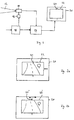
- ein schematisches Blockdiagramm einer Verschaltungsanordnung für eine erfindungsgemäße Kameraeinrichtung,
- Fig. 2a und 2b
- Bildschirmdarstellungen einer erfindungsgemäßen Kameraeinrichtung, wobei bei der Alternative gemäß Fig. 2a das Kamerabild und bei der Alternative gemäß Fig. 2b die Referenzmarke bewegbar sind.
- Fig. 1
- 1 shows a schematic block diagram of an interconnection arrangement for a camera device according to the invention,
- 2a and 2b
- Screen representations of a camera device according to the invention, the camera image being movable in the alternative according to FIG. 2a and the reference mark being movable in the alternative according to FIG. 2b.
In Fig. 1 ist ein schematisches Schaltdiagramm einer Ausführungsform der vorliegenden
Erfindung dargestellt. Eine Kamera 10 nimmt innerhalb eines bestimmten
Aufnahmekegels 12 einen Bereich einer Fahrzeugumgebung um ein (nicht dargestelltes)
Fahrzeug auf. Die Kamera 10 ist am Fahrzeug befestigt und zwar verschwenkbar.
Die Verschwenkung wird mittels eines Aktuators 16 erreicht, der die
Kamera 10 horizontal bewegen kann. In ihrer Normalstellung ist die Kamera 10 in
Längsrichtung des Fahrzeugs ausgerichtet. Durch Beaufschlagen des Aktuators 16
über eine Aktuatorsteuerung 18 erfolgt die Verschwenkung der Kamera 10 in einem
bestimmten Winkel links oder rechts der Fahrzeuglängsachse. Je nach Verschwenkung
der Kamera 10 verändert sich der Aufnahmebereich. Die Aktuatorsteuerung
18 erhält Informationen von einem Navigationssystems sowie den Lenkwinkel und
berechnet aus diesem die Verstellung der Kamera. Die Verstellbefehle für den Aktuator
16 werden zudem an eine Auswerteeinrichtung 14 weitergegeben, die überdies
Bildinformationssignale der Kamera 10 enthält. Die Auswerteeinrichtung 14
verarbeitet die Informationen und gibt einerseits ein Bildsignal an einen Bildschirm
20 ab. Auf dem Bildschirm ist demzufolge ein Kamerabild 22 dargestellt, welches
sich in einer bestimmten Lage zu einer Referenzmarke 24 befindet. Die Referenzmarke
andererseits gibt eine Information über die Fahrzeuglängsachse in Bezug zur
Kameraausrichtung. Durch Relativverschiebung der Referenzmarke 24 und des
Kamerabildes 22 wird dem Fahrer also die Ausrichtung der Kamera bezüglich der
Fahrzeuglängsachse mitgeteilt.1 is a schematic circuit diagram of an embodiment of the present
Invention shown. A
Zwei Ausführungsformen der Relativverschiebung sind in den Figuren 2a und 2b
dargestellt. In Figur 1 ist die in Figur 2a dargestellte Verschiebung realisiert. Demgemäß
wird das Kamerabild 22 je nach Kamerastellung nach links oder rechts verschoben.
Die Referenzmarke 24 bleibt bezüglich des Bildschirmes 20 fest. Hierbei
ist darauf zu achten, daß der Bildschirm 20 in Verschieberichtung größer als das
Kamerabild 22 ausgebildet ist, so daß eine Verschiebung des Kamerabildes 22
möglich wird.Two embodiments of the relative displacement are in Figures 2a and 2b
shown. In Figure 1, the shift shown in Figure 2a is realized. Accordingly
the
Eine Alternative ist in Fig. 2b angegeben. Dort bleibt ein Kamerabild 22' fest. Verschoben
wird hierbei lediglich die Referenzmarke 24'. Hierbei können Bildschirmgröße
20 und Bildgröße 22' übereinstimmen. In diesem Fall liegt die zu verschiebende
Markierung innerhalb des Bildes.An alternative is given in Fig. 2b. A camera image 22 'remains there. Postponed
is only the reference mark 24 '. Here,
Natürlich liefern beide Darstellungen die gleiche Information, nämlich über die Kameraausrichtung
bezüglich der Fahrzeuglängsachse. Je nach gewünschter Ausführungsform
kann jede Variante in der Auswerteeinheit 14 ohne weiteres realisiert
werden. Of course, both representations provide the same information, namely about the camera orientation
with respect to the vehicle's longitudinal axis. Depending on the desired embodiment
Each variant can be easily implemented in the
Mit der vorliegenden Erfindung kann ein Fahrer insgesamt die Ausrichtung der Kamera erkennen und damit wesentlich schneller eine visuelle Übereinstimmung zwischen Kamerabild und Fahrumgebung herstellen.With the present invention, a driver can overall align the camera recognize and thus much faster a visual correspondence between Create camera image and driving environment.
Claims (5)
dadurch gekennzeichnet,
daß am Bildschirm eine Referenzmarke für die Ausrichtung der Fahrzeuglängsachse angezeigt ist,
daß die Verarbeitungseinrichtung Informationen zur Stellung der Kamera bezüglich der Fahrzeuglängsachse erhält und derart ausgebildet ist, daß eine Relativbewegung von dem Bild der Kamera und der Referenzmarke auf dem Bildschirm in Abhängigkeit von der tatsächlichen Stellung der Kamera zur Fahrzeuglängsachse durchführbar istCamera device for a vehicle, comprising a movably arranged camera for recording part of a vehicle environment, a processing device connected to the camera for processing the camera data and a screen coupled to the processing device for displaying the information recorded by the camera in an image,
characterized,
that a reference mark for the alignment of the vehicle's longitudinal axis is displayed on the screen,
that the processing device receives information on the position of the camera with respect to the longitudinal axis of the vehicle and is designed such that a relative movement of the image of the camera and the reference mark on the screen can be carried out as a function of the actual position of the camera relative to the longitudinal axis of the vehicle
dadurch gekennzeichnet,
daß die Lage der Referenzmarke am Bildschirm veränderbar ist. Camera device according to claim 1,
characterized,
that the position of the reference mark on the screen can be changed.
dadurch gekennzeichnet,
daß die Lage des Bildes der Kamera am Bildschirm veränderbar ist.Camera device according to claim 1,
characterized,
that the position of the image of the camera on the screen is changeable.
dadurch gekennzeichnet,
daß die Information zur Stellung der Kamera mittels einem Sensor oder aus der Ansteuerung eines Aktuators für die Kamera ermittelbar ist.Camera device according to one of the preceding claims,
characterized,
that the information about the position of the camera can be determined by means of a sensor or from the control of an actuator for the camera.
dadurch gekennzeichnet,
daß die Kamerastellung in Abhängigkeit von dem Lenkwinkel oder von Informationen eines Navigationssystems veränderbar ist.Camera device according to one of the preceding claims,
characterized,
that the camera position can be changed depending on the steering angle or information from a navigation system.
Applications Claiming Priority (2)
| Application Number | Priority Date | Filing Date | Title |
|---|---|---|---|
| DE19961313 | 1999-12-18 | ||
| DE19961313A DE19961313B4 (en) | 1999-12-18 | 1999-12-18 | Camera device for a vehicle |
Publications (3)
| Publication Number | Publication Date |
|---|---|
| EP1111488A2 true EP1111488A2 (en) | 2001-06-27 |
| EP1111488A3 EP1111488A3 (en) | 2005-04-13 |
| EP1111488B1 EP1111488B1 (en) | 2007-07-25 |
Family
ID=7933325
Family Applications (1)
| Application Number | Title | Priority Date | Filing Date |
|---|---|---|---|
| EP00125844A Expired - Lifetime EP1111488B1 (en) | 1999-12-18 | 2000-11-25 | Camera for a vehicle |
Country Status (3)
| Country | Link |
|---|---|
| EP (1) | EP1111488B1 (en) |
| DE (2) | DE19961313B4 (en) |
| ES (1) | ES2286973T3 (en) |
Cited By (6)
| Publication number | Priority date | Publication date | Assignee | Title |
|---|---|---|---|---|
| CN101881885A (en) * | 2009-04-02 | 2010-11-10 | 通用汽车环球科技运作公司 | Peripheral salient feature on the full-windscreen head-up display strengthens |
| WO2012103886A1 (en) * | 2011-02-02 | 2012-08-09 | Conti Temic Microelectronic Gmbh | Optical device with electro-optical medium |
| CN103029637A (en) * | 2012-12-21 | 2013-04-10 | 广东好帮手电子科技股份有限公司 | Vehicle-mounted far infrared camera module |
| CN103723087A (en) * | 2012-10-12 | 2014-04-16 | 成都众易通科技有限公司 | High-stability vehicle-mounted image pick-up device |
| CN110310486A (en) * | 2019-07-08 | 2019-10-08 | 深圳市道尔智控科技股份有限公司 | A kind of method that image data is transmitted to server-side in parking lot |
| US11958419B2 (en) | 2022-02-24 | 2024-04-16 | Stoneridge, Inc. | Collapsible vehicle camera arm assembly |
Families Citing this family (8)
| Publication number | Priority date | Publication date | Assignee | Title |
|---|---|---|---|---|
| DE10218228A1 (en) * | 2002-04-24 | 2003-11-06 | Volkswagen Ag | Motor vehicle video camera operational checking method in which video data are subjected to plausibility testing in conjunction with other sensor data, such as yaw rate, transverse acceleration, vehicle speed, etc. |
| JP4798945B2 (en) | 2003-03-05 | 2011-10-19 | トヨタ自動車株式会社 | Imaging device |
| DE102005024052B4 (en) * | 2005-05-25 | 2015-02-05 | Robert Bosch Gmbh | Method and device for the controlled selection of predictive sensors for a pedestrian protection system of a motor vehicle |
| DE102006038423A1 (en) * | 2006-08-17 | 2008-02-21 | Bayerische Motoren Werke Ag | Device for calibrating an optical camera and / or an infrared camera |
| DE102007044535B4 (en) * | 2007-09-18 | 2022-07-14 | Bayerische Motoren Werke Aktiengesellschaft | Method for driver information in a motor vehicle |
| DE102007044536A1 (en) | 2007-09-18 | 2009-03-19 | Bayerische Motoren Werke Aktiengesellschaft | Device for monitoring the environment of a motor vehicle |
| ES2363962B1 (en) * | 2008-12-18 | 2012-06-26 | Fundación Para La Promoción De La Innovación, Investigación Y Desarrollo Tecnológico En La Industria De Automoción De Galicia | PICTURE ACQUISITION SYSTEM FOR APPLICATIONS OF DRIVING ASSISTANCE OF AUTOMATIC AUTOMATIC VEHICLES AUTOMATICALLY BASED ON THE DRIVING ENVIRONMENT AND THE VEHICLE OWN. |
| DE102015008553A1 (en) | 2015-07-07 | 2016-02-18 | Daimler Ag | Device and method for adaptive alignment of the camera field of view of a vehicle camera |
Citations (2)
| Publication number | Priority date | Publication date | Assignee | Title |
|---|---|---|---|---|
| US5892855A (en) * | 1995-09-29 | 1999-04-06 | Aisin Seiki Kabushiki Kaisha | Apparatus for detecting an object located ahead of a vehicle using plural cameras with different fields of view |
| FR2785434A1 (en) * | 1998-11-03 | 2000-05-05 | Renault | Motor vehicle driving aid using video images has field of view of cameras altered in real time depending on surroundings |
Family Cites Families (2)
| Publication number | Priority date | Publication date | Assignee | Title |
|---|---|---|---|---|
| SE461797B (en) * | 1989-04-14 | 1990-03-26 | Affarsverket Ffv | DEVICE FOR PAINTING LINE MARKING ON A ROAD |
| KR100270523B1 (en) * | 1995-12-27 | 2000-11-01 | 정몽규 | Unmanned car having control function according to the road condition |
-
1999
- 1999-12-18 DE DE19961313A patent/DE19961313B4/en not_active Expired - Fee Related
-
2000
- 2000-11-25 ES ES00125844T patent/ES2286973T3/en not_active Expired - Lifetime
- 2000-11-25 EP EP00125844A patent/EP1111488B1/en not_active Expired - Lifetime
- 2000-11-25 DE DE50014509T patent/DE50014509D1/en not_active Expired - Lifetime
Patent Citations (2)
| Publication number | Priority date | Publication date | Assignee | Title |
|---|---|---|---|---|
| US5892855A (en) * | 1995-09-29 | 1999-04-06 | Aisin Seiki Kabushiki Kaisha | Apparatus for detecting an object located ahead of a vehicle using plural cameras with different fields of view |
| FR2785434A1 (en) * | 1998-11-03 | 2000-05-05 | Renault | Motor vehicle driving aid using video images has field of view of cameras altered in real time depending on surroundings |
Cited By (8)
| Publication number | Priority date | Publication date | Assignee | Title |
|---|---|---|---|---|
| CN101881885A (en) * | 2009-04-02 | 2010-11-10 | 通用汽车环球科技运作公司 | Peripheral salient feature on the full-windscreen head-up display strengthens |
| CN101881885B (en) * | 2009-04-02 | 2012-08-22 | 通用汽车环球科技运作公司 | Peripheral salient feature enhancement on full-windshield head-up display |
| WO2012103886A1 (en) * | 2011-02-02 | 2012-08-09 | Conti Temic Microelectronic Gmbh | Optical device with electro-optical medium |
| CN103723087A (en) * | 2012-10-12 | 2014-04-16 | 成都众易通科技有限公司 | High-stability vehicle-mounted image pick-up device |
| CN103029637A (en) * | 2012-12-21 | 2013-04-10 | 广东好帮手电子科技股份有限公司 | Vehicle-mounted far infrared camera module |
| CN103029637B (en) * | 2012-12-21 | 2015-11-18 | 广东好帮手电子科技股份有限公司 | A kind of vehicle-mounted far infrared camera module |
| CN110310486A (en) * | 2019-07-08 | 2019-10-08 | 深圳市道尔智控科技股份有限公司 | A kind of method that image data is transmitted to server-side in parking lot |
| US11958419B2 (en) | 2022-02-24 | 2024-04-16 | Stoneridge, Inc. | Collapsible vehicle camera arm assembly |
Also Published As
| Publication number | Publication date |
|---|---|
| DE50014509D1 (en) | 2007-09-06 |
| DE19961313B4 (en) | 2005-06-02 |
| DE19961313A1 (en) | 2001-07-05 |
| ES2286973T3 (en) | 2007-12-16 |
| EP1111488B1 (en) | 2007-07-25 |
| EP1111488A3 (en) | 2005-04-13 |
Similar Documents
| Publication | Publication Date | Title |
|---|---|---|
| DE10109350B4 (en) | Assistance device for reverse parking a vehicle in series | |
| EP1154235B1 (en) | Destination guidance display for navigation systems | |
| EP1825276B1 (en) | Method and device for determining the speed of a vehicle | |
| DE19950033B4 (en) | Camera device for vehicles | |
| EP2895822B1 (en) | Contact-analogue display, in particular of a lane change | |
| DE112015001804B4 (en) | On-board image display device, on-board image display method for vehicle, and on-board image setting device | |
| DE19961313B4 (en) | Camera device for a vehicle | |
| EP2288531B1 (en) | Device and method for generating a locating signal | |
| EP3397523B1 (en) | Method for the representation of a rear outer region of a vehicle | |
| DE10331235A1 (en) | Driving assistance device, in particular for parking a vehicle | |
| DE102010020201A1 (en) | Image displaying method for use in motor vehicle i.e. car, involves representing illustration of images as function of driving mode of motor vehicle, where driving mode is provided with two driving conditions | |
| DE102014116037A1 (en) | Method for operating a driver assistance system of a motor vehicle, driver assistance system and motor vehicle | |
| EP1103823A2 (en) | Method for adjusting a sensor for ranging and direction finding in an vehicle | |
| EP3204889B1 (en) | Method for a motor vehicle provided with a camera, device and system | |
| DE69718068T2 (en) | ASSISTANT SYSTEM FOR GUIDING A VEHICLE, IN PARTICULAR WHEN APPROACHING A STOP | |
| DE10334613A1 (en) | Driving auxiliary device | |
| DE102004003502B3 (en) | Method and device for assistance in guiding a motor vehicle | |
| DE102006037600A1 (en) | Method for resolution based representation of ambience of motor vehicle for use in parking system, involves capturing ambience information from ambience of motor vehicle by image sensor | |
| DE102007011276B4 (en) | Method and device for automatic route determination | |
| DE102007059083A1 (en) | Control system reversible adjustment equipment for e.g. passenger car, has device provided for adjusting control system in dependent of determination whether motor vehicle is operated in left hand driving or in right hand driving | |
| DE60300791T2 (en) | Device and method for operating and positioning a monitoring device for a vehicle | |
| DE102008057670B4 (en) | Method for supporting a vehicle driver of a vehicle, in particular during a reverse drive | |
| WO2013057008A1 (en) | Method for displaying image information on a display unit of a vehicle and driver assistance device for carrying out such a method | |
| DE102012000630B4 (en) | System for detecting an obstacle for a vehicle and a vehicle having a system for detecting an obstacle | |
| DE102014016566A1 (en) | Motor vehicle with camera |
Legal Events
| Date | Code | Title | Description |
|---|---|---|---|
| PUAI | Public reference made under article 153(3) epc to a published international application that has entered the european phase |
Free format text: ORIGINAL CODE: 0009012 |
|
| AK | Designated contracting states |
Kind code of ref document: A2 Designated state(s): AT BE CH CY DE DK ES FI FR GB GR IE IT LI LU MC NL PT SE TR |
|
| AX | Request for extension of the european patent |
Free format text: AL;LT;LV;MK;RO;SI |
|
| PUAL | Search report despatched |
Free format text: ORIGINAL CODE: 0009013 |
|
| AK | Designated contracting states |
Kind code of ref document: A3 Designated state(s): AT BE CH CY DE DK ES FI FR GB GR IE IT LI LU MC NL PT SE TR |
|
| AX | Request for extension of the european patent |
Extension state: AL LT LV MK RO SI |
|
| RIC1 | Information provided on ipc code assigned before grant |
Ipc: 7G 06K 9/36 B Ipc: 7G 05D 1/03 A Ipc: 7B 60R 16/02 B |
|
| 17P | Request for examination filed |
Effective date: 20050429 |
|
| AKX | Designation fees paid |
Designated state(s): DE ES FR GB IT SE |
|
| 17Q | First examination report despatched |
Effective date: 20060630 |
|
| GRAP | Despatch of communication of intention to grant a patent |
Free format text: ORIGINAL CODE: EPIDOSNIGR1 |
|
| GRAS | Grant fee paid |
Free format text: ORIGINAL CODE: EPIDOSNIGR3 |
|
| GRAA | (expected) grant |
Free format text: ORIGINAL CODE: 0009210 |
|
| AK | Designated contracting states |
Kind code of ref document: B1 Designated state(s): DE ES FR GB IT SE |
|
| REG | Reference to a national code |
Ref country code: GB Ref legal event code: FG4D Free format text: NOT ENGLISH |
|
| GBT | Gb: translation of ep patent filed (gb section 77(6)(a)/1977) |
Effective date: 20070725 |
|
| REF | Corresponds to: |
Ref document number: 50014509 Country of ref document: DE Date of ref document: 20070906 Kind code of ref document: P |
|
| REG | Reference to a national code |
Ref country code: SE Ref legal event code: TRGR |
|
| REG | Reference to a national code |
Ref country code: ES Ref legal event code: FG2A Ref document number: 2286973 Country of ref document: ES Kind code of ref document: T3 |
|
| ET | Fr: translation filed | ||
| PLBE | No opposition filed within time limit |
Free format text: ORIGINAL CODE: 0009261 |
|
| STAA | Information on the status of an ep patent application or granted ep patent |
Free format text: STATUS: NO OPPOSITION FILED WITHIN TIME LIMIT |
|
| 26N | No opposition filed |
Effective date: 20080428 |
|
| REG | Reference to a national code |
Ref country code: FR Ref legal event code: PLFP Year of fee payment: 16 |
|
| REG | Reference to a national code |
Ref country code: FR Ref legal event code: PLFP Year of fee payment: 17 |
|
| REG | Reference to a national code |
Ref country code: FR Ref legal event code: PLFP Year of fee payment: 18 |
|
| PGFP | Annual fee paid to national office [announced via postgrant information from national office to epo] |
Ref country code: DE Payment date: 20191112 Year of fee payment: 20 Ref country code: SE Payment date: 20191125 Year of fee payment: 20 |
|
| PGFP | Annual fee paid to national office [announced via postgrant information from national office to epo] |
Ref country code: ES Payment date: 20191216 Year of fee payment: 20 Ref country code: IT Payment date: 20191120 Year of fee payment: 20 Ref country code: FR Payment date: 20191121 Year of fee payment: 20 |
|
| PGFP | Annual fee paid to national office [announced via postgrant information from national office to epo] |
Ref country code: GB Payment date: 20191126 Year of fee payment: 20 |
|
| REG | Reference to a national code |
Ref country code: DE Ref legal event code: R071 Ref document number: 50014509 Country of ref document: DE |
|
| REG | Reference to a national code |
Ref country code: GB Ref legal event code: PE20 Expiry date: 20201124 |
|
| PG25 | Lapsed in a contracting state [announced via postgrant information from national office to epo] |
Ref country code: GB Free format text: LAPSE BECAUSE OF EXPIRATION OF PROTECTION Effective date: 20201124 |
|
| REG | Reference to a national code |
Ref country code: ES Ref legal event code: FD2A Effective date: 20210309 |
|
| PG25 | Lapsed in a contracting state [announced via postgrant information from national office to epo] |
Ref country code: ES Free format text: LAPSE BECAUSE OF EXPIRATION OF PROTECTION Effective date: 20201126 |
|
| P01 | Opt-out of the competence of the unified patent court (upc) registered |
Effective date: 20230502 |