EP1111463A1 - Coating apparatus for photosensitive media - Google Patents
Coating apparatus for photosensitive media Download PDFInfo
- Publication number
- EP1111463A1 EP1111463A1 EP00204441A EP00204441A EP1111463A1 EP 1111463 A1 EP1111463 A1 EP 1111463A1 EP 00204441 A EP00204441 A EP 00204441A EP 00204441 A EP00204441 A EP 00204441A EP 1111463 A1 EP1111463 A1 EP 1111463A1
- Authority
- EP
- European Patent Office
- Prior art keywords
- retractable
- assembly
- format
- media
- coating
- Prior art date
- Legal status (The legal status is an assumption and is not a legal conclusion. Google has not performed a legal analysis and makes no representation as to the accuracy of the status listed.)
- Withdrawn
Links
- 239000011248 coating agent Substances 0.000 title claims abstract description 31
- 238000000576 coating method Methods 0.000 title claims abstract description 31
- 239000000463 material Substances 0.000 claims description 7
- 230000013011 mating Effects 0.000 claims description 4
- 230000000712 assembly Effects 0.000 description 6
- 238000000429 assembly Methods 0.000 description 6
- 230000007246 mechanism Effects 0.000 description 6
- 238000000034 method Methods 0.000 description 3
- 239000011241 protective layer Substances 0.000 description 3
- 239000011253 protective coating Substances 0.000 description 2
- 230000003213 activating effect Effects 0.000 description 1
- 230000006978 adaptation Effects 0.000 description 1
- 230000005540 biological transmission Effects 0.000 description 1
- 230000008859 change Effects 0.000 description 1
- 230000004048 modification Effects 0.000 description 1
- 238000012986 modification Methods 0.000 description 1
- 230000000717 retained effect Effects 0.000 description 1
- 230000000007 visual effect Effects 0.000 description 1
Images




Classifications
-
- G—PHYSICS
- G03—PHOTOGRAPHY; CINEMATOGRAPHY; ANALOGOUS TECHNIQUES USING WAVES OTHER THAN OPTICAL WAVES; ELECTROGRAPHY; HOLOGRAPHY
- G03D—APPARATUS FOR PROCESSING EXPOSED PHOTOGRAPHIC MATERIALS; ACCESSORIES THEREFOR
- G03D15/00—Apparatus for treating processed material
- G03D15/06—Applying varnish or other coating
Definitions
- the present invention relates to improvements in or relating to coating apparatuses and more particularly to a coating apparatus for applying a coating on a photosensitive media.
- a problem with prior art coating devices is that they are set up to either to apply a coating onto a web of photosensitive media or onto individual prints. Accordingly this requires two different separate devices when individual prints and web media are to be coated.
- Applicants have invented an apparatus whereby cut sheets and/or a web of photosensitive media may be coated using a single coating apparatus. This is accomplished by providing means for allowing quick and easy adaptation of the apparatus to either cut sheet or web feed and take-up.
- an apparatus for applying a coating on to photosensitive material comprising:
- the apparatus 10 is a coating apparatus designed for placing a protective layer of a material onto a web or sheet of media.
- the apparatus 10 is designed for placing a protective layer on photographic paper provided either in web or sheet form.
- Figs. land 2 is shown set up in a mode for receiving and applying a coating onto a plurality of individual cut sheets of photographic paper having images thereon and Fig. 3 illustrates the apparatus 10 set up in a second mode for receiving and applying a coating on a continuos web of media, such as photographic paper.
- the apparatus 10 includes a first supply assembly 12 for supplying a media to apparatus 10 of a first format, which in this embodiment is in the form of individual cut sheets, such as photographic prints.
- first supply assembly 12 comprises a tray 13.
- the coating mechanism of apparatus 10 operates as a feed mechanism (not shown) for individually feeding the cut sheets 14 from the tray 13 to the entrance 15 of coating section 16. A coating is applied the individual cut sheets in coating section 16. It is to be understood that any appropriate feed mechanism may be provided.
- the apparatus 10, further includes an output tray 18 for retaining individual prints that have passed through the exit 17 coating section 16.
- the out put output tray 18 may be designed to stack all of the prints one on top of the other or provide separate bins for storing individual or a group of prints.
- the output tray 18 is preferably designed such that it will not interfere with use of a web passing through coating section 16 as illustrated Fig. 3, discussed below.
- a media of a second format passing through apparatus 10 comprises a continuous web 20 of photographic media.
- the web 20 is positioned such that it does not interfere with supply tray 13 or output tray 18 thereby not requiring any major modification or change in operation to the apparatus 10.
- a retractable supply arm assembly 21 is provided for supplying a web 20 of media to coating section 16 and a retractable take-up arm assembly 23 for taking up the web 20 after it leaves coating section 16.
- the assemblies 21, 23 are for use when it is desirable to coat web 20 continuously through apparatus 10.
- the retractable retractable supply arm assembly 21 is positioned on the entrance side of the apparatus 10 for supplying media to entrance 13 and the take-up arm assembly 23 is positioned on the outlet side of apparatus 10 for receiving media from exit 17.
- the assemblies 21, 23 are similar in structure and operation like parts and operation.
- retractable arm assembly 21 in the storage position.
- arm assembly 21 When in the storage position arm assembly 21 is in the non-operational state so that cut sheets can be coated by apparatus 10.
- the supply arm and take-up assemblies 21, 23 do not interfere with the operation of the device and also minimizes the space taken up by apparatus 10.
- Retractable arm assembly 21 includes an outer sleeve 24 having a retractable extension arm 25 which is slidably mounted to sleeve 24.
- the retractable arm 25 has an outer configuration 26 which corresponds to the inner configuration 27 of the outer sleeve 24, but is slightly smaller so as to allow easy movement of sleeve within arm 25.
- the retractable arm 25 has a substantially square cross section, but may be any suitable cross section.
- the outer sleeve 24 is provided with a pair of oppositely disposed slots 28, each designed to receive a projection 30 which extends from the retractable arm 25. Projection 30 is slidable within its associated slot 28.
- the slots 28 each have an inner end 31 and outer end 32 for limiting the movement of projection 30 within slot 28 as illustrated in Figs. 4a and 4b thereby limiting the movement of arm 25.
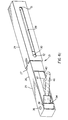
- Fig. 4a illustrates the retractable arm 25 in its stored position
- Fig. 4d illustrates the retractable arm 25 in its fully extended position.
- a retractable mounting pin assembly 34 is rotatably mounted to retractable arm 25 by a pin 36 which extends through the base 38 of pin assembly 34.
- the pin 36 is secured to arm 24 by an any appropriate technique.
- the retractable arm 25 is provided with a recess 40 in which the pin assembly 34 is stored when not in use.
- Figs 4b to Fig. 4d illustrates moving the pin assembly 34 form the stored position (Fig. 4b) to the fully operation position illustrated in Fig. 4d.
- the pin assembly 34 is rotated outward, for example by simply manually operation, as illustrated in Fig. 4c until the mounting pin assembly 34 reaches the fully extended position illustrated in Fig. 4d.
- the mounting pin assembly 34 includes a mounting projection 46 and integral alignment projection 47.
- the mounting projection 46 and alignment projection 47 are designed to engage a mounting slot 48 provided on a roller assembly 50.
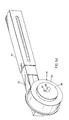
- the mounting slot 48 has a shape designed to mate and receive the mounting projection 46 and alignment projection 47 as illustrated in Fig. 4e.
- the roller assembly 50 is designed to receive a web of photosensitive media that is wound about a supply core 52 as illustrated in Fig. 3.
- the roller assembly 50 includes an outer race 54 that rotate about an inner stationary section 56.
- the roller assembly 50 is brake roller assembly designed to provide a slight braking force so that a sufficient tension is provide to keep the wen taught.
- the stationary section 56 includes the mounting slot 48 for receiving projection 46. As previously discussed an appropriate drive mechanism is provided for taking off of the web from the core on which it is supplied.
- retractable arm assembly 23 which is similar to arm assembly 21 like numerals indicating like parts an operation.
- Arm assembly 23 is different from assembly 21 in that a drive assembly 62 is provided with assembly 23 to drive take-up roller 51 placed thereon.
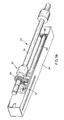
- Figs. 5a and 5b illustrate the arm assembly in the retracted state.
- the arm assembly 23 partially broken illustrating the internal components and how it is mates with the drive of apparatus 10:
- a transmission shaft 64 is slidably mounted to assembly 23 such that is moves with extension arm 25.
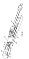
- Fig 5c illustrates the arm assembly 23 moving from the position in Fig. 5a to the fully extended position in Figs. 5e and 5f.
- a first bevel gear 66 is provided at the rear section of shaft 64 which is designed to engage mating gear 67 which in turn engages a drive gear 68 on drive shaft 70 in apparatus 10 when the assembly is in the fully extended position as illustrated in Figs. 5e-5f.
- the gear 66 is disengaged from gear 67.
- the forward end of shaft 64 is provided with a second bevel gear 72, see Figs 5b and 5c, which is designed to engage a mating bevel gear 74 on the back of base 38 of pin assembly 34, see Figs. 5c and 5f.
- the mounting projection 46 is designed to rotate the inner race 56.
- the roller assemblies 50, 51 are placed in the storage bin 60 and the retractable arms 25 are retracted into the outer housing sleeves 24.
- the retractable arm assemblies 21, 23 are opened to the operation position.
- a single retractable arm assembly is provided on the supply and take-up side of the coating apparatus, the present invention is not so limited. If desired a pair of aligned arm assemblies may be provided on each side of the apparatus 10 so that the core is retained on both sides.
Landscapes
- Physics & Mathematics (AREA)
- General Physics & Mathematics (AREA)
- Replacement Of Web Rolls (AREA)
- Photographic Processing Devices Using Wet Methods (AREA)
- Silver Salt Photography Or Processing Solution Therefor (AREA)
- Photographic Developing Apparatuses (AREA)
Abstract
A coating apparatus for applying a coating on to a photographic
media. The apparatus includes a coating section (16) for applying a
coating on to a photosensitive media having an entrance and an exit. A
first supply assembly (12) is provided for supplying a first media of a
first format adjacent the entrance. A retractable second retractable
supply assembly and a retractable taking-up assembly (23) is provided
for supplying and taking up a second media of a second format, the
second format being different from the first format.
Description
- The present invention relates to improvements in or relating to coating apparatuses and more particularly to a coating apparatus for applying a coating on a photosensitive media.
- It has been found desirable to place a protective coating on photographic media. In particular, photographic prints are relatively sensitive to fingerprints, moisture, and other dirt that may be placed on the surface. Because photographic prints are designed to be viewed, the appearance of fingerprints, smudges or other dirt on the surface thereof can substantially detract from the visual appearance thereof. It has been suggested to provide of a thin protective layer on the photosensitive photographic print. An example of a suitable device for applying such a coating is described in U.S. patents 5,984,534; 5,905,924; 5,875,370 and EP patent application no. 99201482.9 filed May 12, 1999 entitled "Method and Apparatus for Applying a Solution to a Photosensitive Material" by Ralph L. Piccinino Jr. and Kevin Blakely.
- A problem with prior art coating devices is that they are set up to either to apply a coating onto a web of photosensitive media or onto individual prints. Accordingly this requires two different separate devices when individual prints and web media are to be coated.
- Applicants have invented an apparatus whereby cut sheets and/or a web of photosensitive media may be coated using a single coating apparatus. This is accomplished by providing means for allowing quick and easy adaptation of the apparatus to either cut sheet or web feed and take-up.
- In accordance with the present invention there is provided an apparatus for applying a coating on to photosensitive material. The apparatus comprising:
- a coating section for applying a coating on to a photosensitive media having an entrance and an exit;
- a first supply assembly for supplying a first media of a first format adjacent the entrance; and
- a retractable second retractable supply assembly and a retractable taking-up assembly for supplying and taking up a second media of a second format, the second format being different form said first format.
-
- The above, and other objects, advantages and novel features of the present invention will become more apparent from the accompanying detailed description thereof when considered in conjunction with the following drawings.
- In the detailed description of the preferred embodiments of the invention presented below, reference is made to the accompanying drawings in which:
- Fig. 1 is a perspective view of an apparatus made in accordance to the present invention in the cut sheet mode of operation as taken from the exit side;
- Fig. 2 is a perspective view of the apparatus of Fig. 1 as taken from the supply side;
- Fig. 3 is a side elevational view of the apparatus of Fig. 1 when in the web feed mode of operation.;
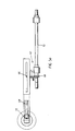
- Figs. 4a - 4e illustrate the sequential steps of opening one of the retractable arm assembly for receiving a supply or take-up core about which a web of photosensitive material may be helically wound; and
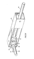
- Figs 5a - 5f illustrate the sequential steps of opening the other arm assembly having a drive mechanism for driving of the take-up roller.
-
- The present description will be directed in particular to elements forming part of, or in cooperation more directly with, the apparatus in accordance with the present invention. It is understood that elements not specifically shown or described may take various forms well known to those skilled in the art.
- Referring to Figs. 1 and 2 there is illustrated an
apparatus 10 made in accordance to the present invention. Theapparatus 10 is a coating apparatus designed for placing a protective layer of a material onto a web or sheet of media. In the particular embodiment illustrated theapparatus 10 is designed for placing a protective layer on photographic paper provided either in web or sheet form. U.S. patents 5,984,534; 5,905,924; 5,875,370 and EP patent application no. 99201482.9 filed May 12, 1999 entitled "Method and Apparatus for Applying a Solution to a Photosensitive Material" by Ralph L. Piccinino Jr. and Kevin Blakely, disclose suitable devices for applying a protective coating on a media, all of which are incorporated by reference herein. - The
apparatus 10 in Figs. land 2 is shown set up in a mode for receiving and applying a coating onto a plurality of individual cut sheets of photographic paper having images thereon and Fig. 3 illustrates theapparatus 10 set up in a second mode for receiving and applying a coating on a continuos web of media, such as photographic paper. - Referring to Figs 1 and 2, the
apparatus 10 includes afirst supply assembly 12 for supplying a media toapparatus 10 of a first format, which in this embodiment is in the form of individual cut sheets, such as photographic prints. In the particular embodiment illustratedfirst supply assembly 12 comprises atray 13. The coating mechanism ofapparatus 10 operates as a feed mechanism (not shown) for individually feeding thecut sheets 14 from thetray 13 to the entrance 15 ofcoating section 16. A coating is applied the individual cut sheets incoating section 16. It is to be understood that any appropriate feed mechanism may be provided. Theapparatus 10, further includes anoutput tray 18 for retaining individual prints that have passed through the exit 17coating section 16. The out putoutput tray 18 may be designed to stack all of the prints one on top of the other or provide separate bins for storing individual or a group of prints. Theoutput tray 18 is preferably designed such that it will not interfere with use of a web passing throughcoating section 16 as illustrated Fig. 3, discussed below. - In Fig. 3 there is illustrated a media of a second format passing through
apparatus 10. As can be seen the second format comprises acontinuous web 20 of photographic media. Theweb 20 is positioned such that it does not interfere withsupply tray 13 oroutput tray 18 thereby not requiring any major modification or change in operation to theapparatus 10. In this embodiment, a retractablesupply arm assembly 21 is provided for supplying aweb 20 of media to coatingsection 16 and a retractable take-up arm assembly 23 for taking up theweb 20 after it leavescoating section 16. Theassemblies web 20 continuously throughapparatus 10. The retractable retractablesupply arm assembly 21 is positioned on the entrance side of theapparatus 10 for supplying media toentrance 13 and the take-up arm assembly 23 is positioned on the outlet side ofapparatus 10 for receiving media from exit 17. Theassemblies - Referring to Figs. 4a-4d there illustrated in greater detail
retractable arm assembly 21 in the storage position. When in the storageposition arm assembly 21 is in the non-operational state so that cut sheets can be coated byapparatus 10. When in the storage position the supply arm and take-up assemblies apparatus 10.Retractable arm assembly 21 includes anouter sleeve 24 having aretractable extension arm 25 which is slidably mounted tosleeve 24. Preferably as illustrated, theretractable arm 25 has anouter configuration 26 which corresponds to theinner configuration 27 of theouter sleeve 24, but is slightly smaller so as to allow easy movement of sleeve withinarm 25. In the particular embodiment illustrated, theretractable arm 25 has a substantially square cross section, but may be any suitable cross section. Theouter sleeve 24 is provided with a pair of oppositely disposedslots 28, each designed to receive aprojection 30 which extends from theretractable arm 25.Projection 30 is slidable within its associatedslot 28. Theslots 28 each have aninner end 31 andouter end 32 for limiting the movement ofprojection 30 withinslot 28 as illustrated in Figs. 4a and 4b thereby limiting the movement ofarm 25. Fig. 4a illustrates theretractable arm 25 in its stored position and Fig. 4d illustrates theretractable arm 25 in its fully extended position. - A retractable
mounting pin assembly 34 is rotatably mounted toretractable arm 25 by apin 36 which extends through thebase 38 ofpin assembly 34. Thepin 36 is secured to arm 24 by an any appropriate technique. Theretractable arm 25 is provided with arecess 40 in which thepin assembly 34 is stored when not in use. Figs 4b to Fig. 4d illustrates moving thepin assembly 34 form the stored position (Fig. 4b) to the fully operation position illustrated in Fig. 4d. After theretractable arm 24 has been fully extended, thepin assembly 34 is rotated outward, for example by simply manually operation, as illustrated in Fig. 4c until the mountingpin assembly 34 reaches the fully extended position illustrated in Fig. 4d. The mountingpin assembly 34 includes a mountingprojection 46 andintegral alignment projection 47. The mountingprojection 46 andalignment projection 47 are designed to engage a mountingslot 48 provided on aroller assembly 50. In particular, the mountingslot 48 has a shape designed to mate and receive the mountingprojection 46 andalignment projection 47 as illustrated in Fig. 4e. Theroller assembly 50 is designed to receive a web of photosensitive media that is wound about asupply core 52 as illustrated in Fig. 3. In the preferred embodiment illustrated theroller assembly 50 includes anouter race 54 that rotate about an innerstationary section 56. Theroller assembly 50 is brake roller assembly designed to provide a slight braking force so that a sufficient tension is provide to keep the wen taught. Thestationary section 56 includes the mountingslot 48 for receivingprojection 46. As previously discussed an appropriate drive mechanism is provided for taking off of the web from the core on which it is supplied. - Referring to Figs 5a-5f there is illustrated
retractable arm assembly 23, which is similar toarm assembly 21 like numerals indicating like parts an operation.Arm assembly 23 is different fromassembly 21 in that adrive assembly 62 is provided withassembly 23 to drive take-uproller 51 placed thereon. Figs. 5a and 5b illustrate the arm assembly in the retracted state. In Fig. 5b thearm assembly 23 partially broken illustrating the internal components and how it is mates with the drive of apparatus 10: As illustrated in Figs 5a-5f atransmission shaft 64 is slidably mounted toassembly 23 such that is moves withextension arm 25. Fig 5c illustrates thearm assembly 23 moving from the position in Fig. 5a to the fully extended position in Figs. 5e and 5f. Afirst bevel gear 66 is provided at the rear section ofshaft 64 which is designed to engagemating gear 67 which in turn engages adrive gear 68 ondrive shaft 70 inapparatus 10 when the assembly is in the fully extended position as illustrated in Figs. 5e-5f. When in the retracted position as illustrated in Figs. 5a and 5b, thegear 66 is disengaged fromgear 67. The forward end ofshaft 64 is provided with asecond bevel gear 72, see Figs 5b and 5c, which is designed to engage amating bevel gear 74 on the back ofbase 38 ofpin assembly 34, see Figs. 5c and 5f. In this embodiment the mountingprojection 46 is designed to rotate theinner race 56. Once thearm 25 in it fully extended position,projection 46 is rotated outward as illustrated in Fig. 5f so thatgear 74 engagesgear 72. Therefore onceshaft 70 is rotated theroller 51 mounted onprojection 46 will rotate. It is of course understood that appropriate controls are provided for activating and stoppingdrive shaft 70 as needed. Theroller 51 is designed to operate as a slip clutch. Therefore if too much tension is provided, theouter race 54 will slip with respect to theouter race 56. - When operating the
apparatus 10 in the cut sheet mode, theroller assemblies retractable arms 25 are retracted into theouter housing sleeves 24. When operating theapparatus 10 in the web mode, theretractable arm assemblies - In the particular embodiment illustrated only a single retractable arm assembly is provided on the supply and take-up side of the coating apparatus, the present invention is not so limited. If desired a pair of aligned arm assemblies may be provided on each side of the
apparatus 10 so that the core is retained on both sides.
Claims (10)
1. An apparatus for applying a coating on to photosensitive
material, said apparatus comprising:
a coating section for applying a coating on to a photosensitive
media having an entrance and an exit;
a first supply assembly for supplying a first media of a first format
adjacent said entrance; and
a retractable second retractable supply assembly and a retractable
taking-up assembly for supplying and taking up a second media of a second
format, said second format being different form said first format.
2. An apparatus for applying a coating on to photosensitive
material, said apparatus comprising:
a first supply assembly for supplying a first media of a first format,
said first format comprising a cut sheet format.; and
a retractable second supply assembly and a retractable taking-up
assembly for supplying and taking-up a second media of a second format, said
second format comprising a web format, said retractable second supply assembly
and said retractable take-up assembly each comprising a retractable arm assembly.
2. An apparatus according to claim 1 wherein said first supply
assembly does not interfere with use of said retractable second supply assembly.
3. An apparatus according to claim 1 wherein said first format
is a cut sheet format and said second format is a web format.
4. An apparatus according to claim 1 wherein said retractable
second supply assembly comprises a retractable arm assembly.
5. An apparatus according to claim 4 wherein said retractable
arm assembly comprises an outer sleeve and an extension arm slidable mounted to
said outer sleeve.
6. An apparatus according to claim 5 wherein said retractable
arm assembly further includes a rotatably mounted retractable mounting pin
assembly, said mounting pin assembly including a mounting projection placement
in a mating slot of a roller assembly.
7. An apparatus according to claim 6 wherein said roller
assembly comprises an outer race which rotates about a stationary section, said
stationary section having said mating slot.
8. An apparatus according to claim 2 wherein said retractable
supply assembly and retractable take-up assembly each comprises an outer sleeve
and an extension arm slidable mounted to said outer sleeve.
9. An apparatus according to claim 2 wherein said retractable
arm assembly includes a slidable shaft which engages a drive shaft in said
apparatus.
Applications Claiming Priority (2)
| Application Number | Priority Date | Filing Date | Title |
|---|---|---|---|
| US09/470,723 US6394024B1 (en) | 1999-12-22 | 1999-12-22 | Coating apparatus for photosensitive media |
| US470723 | 1999-12-22 |
Publications (1)
| Publication Number | Publication Date |
|---|---|
| EP1111463A1 true EP1111463A1 (en) | 2001-06-27 |
Family
ID=23868770
Family Applications (1)
| Application Number | Title | Priority Date | Filing Date |
|---|---|---|---|
| EP00204441A Withdrawn EP1111463A1 (en) | 1999-12-22 | 2000-12-11 | Coating apparatus for photosensitive media |
Country Status (3)
| Country | Link |
|---|---|
| US (1) | US6394024B1 (en) |
| EP (1) | EP1111463A1 (en) |
| JP (1) | JP2001183803A (en) |
Families Citing this family (1)
| Publication number | Priority date | Publication date | Assignee | Title |
|---|---|---|---|---|
| US9096084B1 (en) * | 2014-11-14 | 2015-08-04 | Eastman Kodak Company | Printer for sheet and web printing |
Citations (3)
| Publication number | Priority date | Publication date | Assignee | Title |
|---|---|---|---|---|
| US5309192A (en) * | 1992-08-24 | 1994-05-03 | Lu Chia Chang | Photo coating machine |
| EP0915377A1 (en) * | 1997-11-06 | 1999-05-12 | Eastman Kodak Company | A method and apparatus of applying a solution of a predetermined viscosity to photosensitive material to form a protective coating thereon |
| EP0915380A1 (en) * | 1997-11-06 | 1999-05-12 | Eastman Kodak Company | A replaceable cartridge coating assembly and method of coating a photosensitive material using the same |
Family Cites Families (11)
| Publication number | Priority date | Publication date | Assignee | Title |
|---|---|---|---|---|
| BE793607A (en) | 1972-01-05 | 1973-07-02 | Hoechst Co American | APPARATUS FOR PROCESSING BOTH SIDES OF A PRINTING PLATE |
| DE2951802A1 (en) | 1979-12-21 | 1981-07-09 | Agfa-Gevaert Ag, 5090 Leverkusen | DEVICE AND METHOD FOR FULLY AUTOMATIC LACQUERING OF BAND-SHAPED MATERIALS |
| US4365733A (en) * | 1981-05-07 | 1982-12-28 | Mcnew Thomas A | System for passing elongated paper through a reproducing apparatus |
| US4530306A (en) | 1984-01-06 | 1985-07-23 | Graphic Enterprises Of Ohio, Inc. | Coating device for plates |
| DE3631668A1 (en) | 1986-09-18 | 1988-03-24 | Hoechst Ag | DEVICE FOR PROCESSING PHOTO SENSITIVE MATERIALS |
| JPH01101171A (en) * | 1987-10-09 | 1989-04-19 | Internatl Business Mach Corp <Ibm> | Continuous paper-cut paper feeder |
| US5228920A (en) | 1991-06-03 | 1993-07-20 | Thompson Iii Ernest E | Film coating unit |
| US5297783A (en) * | 1991-11-12 | 1994-03-29 | Pitney Bowes Inc. | Apparatus and system for handling cut sheets and web forms to form discrete batches |
| US5439704A (en) | 1993-10-27 | 1995-08-08 | Hunter Engineering Company, Inc. | Combined coil and blank powder coating |
| SE510049C2 (en) | 1996-03-25 | 1999-04-12 | Ericsson Telefon Ab L M | Device for connecting at least one waveguide to an optical transmitter or receiver |
| US5875370A (en) | 1997-11-06 | 1999-02-23 | Eastman Kodak Company | Coating apparatus having a removable coating module for applying a protective coating to photosensitive material |
-
1999
- 1999-12-22 US US09/470,723 patent/US6394024B1/en not_active Expired - Fee Related
-
2000
- 2000-12-11 EP EP00204441A patent/EP1111463A1/en not_active Withdrawn
- 2000-12-22 JP JP2000390917A patent/JP2001183803A/en active Pending
Patent Citations (3)
| Publication number | Priority date | Publication date | Assignee | Title |
|---|---|---|---|---|
| US5309192A (en) * | 1992-08-24 | 1994-05-03 | Lu Chia Chang | Photo coating machine |
| EP0915377A1 (en) * | 1997-11-06 | 1999-05-12 | Eastman Kodak Company | A method and apparatus of applying a solution of a predetermined viscosity to photosensitive material to form a protective coating thereon |
| EP0915380A1 (en) * | 1997-11-06 | 1999-05-12 | Eastman Kodak Company | A replaceable cartridge coating assembly and method of coating a photosensitive material using the same |
Also Published As
| Publication number | Publication date |
|---|---|
| JP2001183803A (en) | 2001-07-06 |
| US6394024B1 (en) | 2002-05-28 |
Similar Documents
| Publication | Publication Date | Title |
|---|---|---|
| US6394730B1 (en) | Method and apparatus for making an album page | |
| US20020192001A1 (en) | Method and apparatus for making an album page | |
| JPH02147272A (en) | Tape supply system of thermal printer, etc. | |
| EP0762190B1 (en) | Paper magazine | |
| JPH05178525A (en) | Coating film transfer tool | |
| US5927192A (en) | Stencil and stencil perforating device | |
| US6394024B1 (en) | Coating apparatus for photosensitive media | |
| JP2977101B2 (en) | Decal device | |
| EP0629902B1 (en) | Continuous film feed device and method therefor | |
| JP4116685B2 (en) | Label unwinding device for labeling machine | |
| JP2000211785A (en) | Printer | |
| JP4390161B2 (en) | Label peeling device | |
| US7128290B1 (en) | Spool having a dual purpose cam | |
| JP3155606B2 (en) | Colorant-carrying film supply device | |
| JP2004262499A (en) | Label printer | |
| JP4121334B2 (en) | Color proofing apparatus having registration means | |
| US20080029022A1 (en) | Device for automatically pasting sheets of paper or cardboard | |
| EP1657068B1 (en) | Printer and supply unit for said printer | |
| JPH10129053A (en) | Printer | |
| JP2000211777A (en) | Printer | |
| JP2565494B2 (en) | Thermal transfer printing mechanism | |
| GB2321877A (en) | Stencil perforating device | |
| JP3199994B2 (en) | Image forming apparatus using thermal ink sheet | |
| JP3473804B2 (en) | Plate cylinder of stencil type stencil printing machine | |
| JPH0376672A (en) | Printer |
Legal Events
| Date | Code | Title | Description |
|---|---|---|---|
| PUAI | Public reference made under article 153(3) epc to a published international application that has entered the european phase |
Free format text: ORIGINAL CODE: 0009012 |
|
| AK | Designated contracting states |
Kind code of ref document: A1 Designated state(s): CH DE FR GB IT LI |
|
| AX | Request for extension of the european patent |
Free format text: AL;LT;LV;MK;RO;SI |
|
| 17P | Request for examination filed |
Effective date: 20011121 |
|
| AKX | Designation fees paid |
Free format text: CH DE FR GB IT LI |
|
| STAA | Information on the status of an ep patent application or granted ep patent |
Free format text: STATUS: THE APPLICATION HAS BEEN WITHDRAWN |
|
| 18W | Application withdrawn |
Effective date: 20040213 |