EP1111364A1 - Damage detection of motor pieces - Google Patents
Damage detection of motor pieces Download PDFInfo
- Publication number
- EP1111364A1 EP1111364A1 EP00403616A EP00403616A EP1111364A1 EP 1111364 A1 EP1111364 A1 EP 1111364A1 EP 00403616 A EP00403616 A EP 00403616A EP 00403616 A EP00403616 A EP 00403616A EP 1111364 A1 EP1111364 A1 EP 1111364A1
- Authority
- EP
- European Patent Office
- Prior art keywords
- frequency
- signal
- fault
- sequences
- threshold
- Prior art date
- Legal status (The legal status is an assumption and is not a legal conclusion. Google has not performed a legal analysis and makes no representation as to the accuracy of the status listed.)
- Granted
Links
Images

Classifications
-
- G—PHYSICS
- G01—MEASURING; TESTING
- G01M—TESTING STATIC OR DYNAMIC BALANCE OF MACHINES OR STRUCTURES; TESTING OF STRUCTURES OR APPARATUS, NOT OTHERWISE PROVIDED FOR
- G01M15/00—Testing of engines
- G01M15/04—Testing internal-combustion engines
- G01M15/12—Testing internal-combustion engines by monitoring vibrations
-
- G—PHYSICS
- G01—MEASURING; TESTING
- G01H—MEASUREMENT OF MECHANICAL VIBRATIONS OR ULTRASONIC, SONIC OR INFRASONIC WAVES
- G01H1/00—Measuring characteristics of vibrations in solids by using direct conduction to the detector
- G01H1/003—Measuring characteristics of vibrations in solids by using direct conduction to the detector of rotating machines
-
- G—PHYSICS
- G01—MEASURING; TESTING
- G01H—MEASUREMENT OF MECHANICAL VIBRATIONS OR ULTRASONIC, SONIC OR INFRASONIC WAVES
- G01H1/00—Measuring characteristics of vibrations in solids by using direct conduction to the detector
- G01H1/12—Measuring characteristics of vibrations in solids by using direct conduction to the detector of longitudinal or not specified vibrations
- G01H1/14—Frequency
-
- G—PHYSICS
- G01—MEASURING; TESTING
- G01M—TESTING STATIC OR DYNAMIC BALANCE OF MACHINES OR STRUCTURES; TESTING OF STRUCTURES OR APPARATUS, NOT OTHERWISE PROVIDED FOR
- G01M13/00—Testing of machine parts
- G01M13/02—Gearings; Transmission mechanisms
- G01M13/028—Acoustic or vibration analysis
Definitions
- the invention relates to the field of processes permanent monitoring of a mechanical part in particular an important rotating part of an engine for example a bearing or a gear of a airplane engine.
- the method according to the invention is relating to a surveillance in which the signal from one or more acceleration sensors. Processing the vibration signal from the sensor leads to the determination of one or more quantities resulting from the signal or derived from the signal by the treatment. These quantities are compared with thresholds to detect that the monitored mechanical part has suffered damage.
- the detection of such anomalies should allow a lifetime forecast remaining room under surveillance before serious damage leading to rupture or serious malfunction.
- the result of the treatment is such that damage can be detected in a way sufficiently early that at the time of detection, the organ is still functioning satisfactorily and that there is reasonable certainty that it will continue to function satisfactorily, from preferably until a next periodic visit from this organ and at least until a next stopover when the organ is mounted on a flying machine.
- Patent applications EP 0 889 313 to 316 A2 filed simultaneously on July 3, 1998 offer a good example of such methods.
- fifteen acceleration sensors and two azimuth sensors intended to receive rotational speeds are arranged in various places at proximity of organs making up a block of transmission of movements to rotary organs of a helicopter, especially the rotor shaft and the rear stabilization propeller.
- a 6 th order moment of this time signal is calculated, which is compared to a predetermined threshold to possibly activate an alarm.
- the method described in application '313 is intended to predict the arrival of an anomaly located at the level of an external shaft.
- the processing then described in application '314 provides for the selection of a determined sample of frequency, the calculation of the amplitude of this sample and its comparison to a reference value, the result being compared to a threshold.
- the processing then described in application '315 provides for the selection of two groups of samples of frequency, calculating the energy associated with these two groups, an energy gap calculation between the two groups and comparing this deviation to a threshold.
- This method is intended to detect a fault on a shaft with two gears.
- the processing described in the '316 application provides after the acquisition phase, a Hilbert transformation of the signal obtained, the definition of a complex number having the signal for real part and the Hilbert transform partly imaginary, calculating the phase of this complex number and its derivative with respect to time and finally the comparison of this derivative with a threshold value.
- the invention is intended to detect in a manner early damage occurring in particular to a rotating part of an engine for example a bearing with balls or rollers, or a gear. It is however possible to extend the scope of the invention to a room non-rotating, for example a fixed part for example a rollover or mobile according to another movement, by example a connecting rod or a valve and its stem.
- a digital capture of the signal delivered by at least one dedicated acceleration sensor for monitoring vibration of the engine. This time signal is then, as in the prior art, transformed in the field frequency.
- a filtering is then performed to select characteristic frequencies of the defect sought and which have been called in the cited patents "frequencies of meshing ". Treatments are then carried out on these characteristic frequencies to obtain quantities that can be compared to thresholds for draw conclusions about a possible damage to the mechanical part followed.
- the inventors of the present invention have noticed that the frequency signal obtained from transformation of the time signal from the sensor is very noisy. They also noticed that the signal corresponding to what has been called the frequency of meshing arrives very weakly at the level from the sensor, so it's difficult to isolate the possible presence of this engagement frequency ambient noise necessarily present on an engine.
- this "mesh frequency" can be present even in the absence of a defect, simply because the teeth mesh with each other. What it should to detect is therefore a significant change in the spectrum associated with this mesh frequency, by example a modification of the number of harmonic lines of this frequency and / or the amplitude of vibration at this mesh frequency or its harmonics.
- this gear frequency could be present in time that frequency of modification of one or more fundamental frequencies of the motor.
- frequencies of the motor we designate the frequency of rotation -number of revolutions per second- of the motor, or for engines with a low pressure compressor and a high pressure compressor, the frequencies of rotation of each of these bodies.
- a fundamental frequency of a motor is a frequency of rotation of a large part, from the point moment of inertia view of the engine.
- a frequency resulting from damage will be a frequency at which this damage produces a shock.
- the frequency of training or rolling would result of a succession at this pulse frequency of DIRAC.
- the problem is therefore to identify the presence or modification of characteristics of this frequency resulting from damage sufficiently stable and constant to isolate it from noise, and conclude that there is a defect in the part monitored, this without generating false alarms. he is also important to spot this frequency resulting from damage while the defect causing the appearance of this frequency is still at a stage early in its development.
- an early stage consists of a simple flaking of one of the running surfaces.
- the magnitude of the frequency or changing the characteristics of its associated spectrum, resulting from the defect is low by so it's hard to tell them apart from the noise.
- the correlation of two functions is the measure of the resemblance which exists between them: basically a comparison process.
- the signals are represented by sequences of numbers which are successive samples of a continuous waveform.
- the signal delivered by the sensor will include the fundamental frequencies F N1 and F N2 . It could also include the harmonic frequencies of these frequencies, for example 2F N1 , 3F N1 , 2F N2 , 3F 2 .
- the transmission chain is such that a signal comprising the frequency F N1 passes through a vibrating member in particular for example at the frequency 2F N2 , there will be frequencies resulting from a modulation of one frequency by another, for example 2F N2 + F N1 , 2F N2 - F N1 .
- the spectrum of an engine will present for each particular case, that is to say for each type of engine and each location of the sensor and also for engine speed ranges a spectrum of characteristic lines.
- a consistency calculation sliding i.e. by varying the offset V step by step from resulting frequency values combinations of fundamental values obtained over small multiples of the fundamental frequencies by example multiples included, bounds included, between 0 and 4 and around these combinations, will identify for the engine speeds studied, for example for the longest used diets during of each flight, the lines normally present, i.e. in the absence of faults. Then perform the same line search with a motor equipped with a part presenting at an early stage the defect that we will then seek to detect.
- the spectrum resulting from the defect must be is different from the spectrum in normal operation, by the presence of a frequency which is not present with sufficient amplitude to be detected even at by means of spectral coherence calculation. Indeed, a possible modification of the amplitude of this frequency due to the presence of the fault does not not necessarily a significant variation in the value of the coherence peak.
- the p detection values that are uses to establish the detection ratio are values corresponding to P sequences chosen from most recent recorded in diet ranges engine considered interesting. It will not be necessarily the most recent in time so absolute, but of the most recent in these ranges of engine speed which will be judged particularly interesting.
- the number P is a whole number greater than or equal to 1.
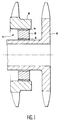
- the method according to the invention was used for the monitoring the state of a rotor bearing of a engine. This level is very clearly represented schematic in axial section in Figure 1.
- the bearing comprises a bearing 1 with rollers 2. Rollers roll between two rings, one ring internal 3 and an external ring 4.
- the inner ring 3 centers a shaft 5 of a rotor a low pressure engine body. This body is not otherwise shown as it is not useful for the understanding of the invention.
- the outer ring 4 center a shaft 6 of a high pressure body of the same engine.
- a rolling factor ⁇ is defined as the ratio between the diameter d of a roller to the diameter dm of the middle cylinder of the two rings 3 and 4.
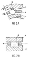
- the defect that we are trying to detect is a defect of the outer ring 4 of the bearing by example flaking. This defect is represented by a star in Figure 2a.
- the frequency f D resulting from the damage will be equal to the number of times a roller hits the fault.
- this frequency fD is proportional to the difference N2 -N 1 between the number of turns per second of the outer ring and the number of turns per second of the inner ring.
- a consistency calculation is performed between the Fourier transform of the received vibrational signal and the Fourrier transform of the same signal shifted by cyclic frequency V.
- the estimation method used is that of the averaged periodogram which uses the fast Fourier transform.
- Max and LACOUME signal processing methods and techniques and applications to physical, Volume 1: General principles and conventional methods" 5th edition, 1996 MASSON.
- Spectral coherence is normalized therefore between 0 and 1. Taking into account that we are working on a signal of finite duration and more noisy, we cannot have values equal to 0 or 1.
- treatment according to the invention is started.
- the subsequences partially overlap one the other, for example by 50%.
- the average consistency is equal to the mean of the consistency samples.
- the consistency normalized mean is above a threshold of 0.8, there are consistency and we memorize it. We then continue the treatment as described above.
- the number of sequences with positive coherence is greater at a predetermined threshold, or what amounts to the same if the ratio of the number of positive coherences to at the number p of sequences is greater than a threshold, it is decided that there is a fault.
- this frequency is (F N2 -F N1 ) as explained above.
- a step 10 we proceed with the acquisition and backup for example by storing data from a vibrating signal sensor acceleration. As already explained above we do not not save the sequences for which the engine speed is unstable during frequency recording.
- a step 11 the transformation of Fast Fourrier (FFT) and filtering to eliminate frequencies resulting from the rotation of rotor assemblies at strong kinetic moment like high and low bodies pressure.
- FFT Fast Fourrier
- a step 12 one performs calculations of spectral coherence with corresponding V offsets at the fault frequency, or at each of the frequencies resulting from the rotation of the upper and lower bodies pressure.
- a step 13 optionally a level 3 message if one of the results 1, 2 or 3 described above is obtained.
- step 11 of transformation into frequency signal and filtering on compare in a step 14 the amplitude level of higher signal amplitudes frequency has a first low threshold.
- step 14 If in step 14 we see that the amplitudes more important of the frequency signal are lower at the first low threshold, parallel processing stops. In such a case, the processing involves only the steps 10, 11, 12 and possibly 13.
- step 17 If on the other hand it is noted that the amplitudes the most important of the frequency signal are stably higher than the first low threshold we will look at a step 17, if the degree of harmonic differential of at least one of the frequencies above the low threshold is stable. In the affirmative a level 2 message will be sent in step 18. If the higher the amplitudes the more important the signal are higher than the second high threshold and that we observe at step 17 that the degree of differential harmonic is stable then a step 19 message will be sent level 1.
- the degree or differential harmonic ratio is obtained by dividing the frequency of the spectrum with a high amplitude by the fault frequency (F N2 - F N1 ).
- the threshold value of the coherence peak is set at 0.8.
- the numbers p, a and b and the second threshold predetermined are independent of each other. However by construction, the second threshold predetermined is less than 1, and b ⁇ a.
- Level 2 and 3 messages are issued if stably, i.e. for at least b sequences taken from a the amplitudes are greater than first low threshold or first high threshold. We notice obviously if an amplitude is above the threshold high it is necessarily higher than the low threshold. It may therefore happen that we have to issue simultaneously a level 2 message and a message from level 1. In this case, we will only send the message level 1.
- the difference with step 12 case 1 or 2 is that in step 17 we look at the constancy of the differential harmonic ratio.
Abstract
Description
L'invention se situe dans le domaine des procédés de surveillance permanente d'une pièce mécanique en particulier une pièce rotative importante d'un moteur par exemple un roulement de palier ou un engrenage d'un moteur d'avion. Le procédé selon l'invention est relatif à une surveillance dans laquelle on traite le signal issu d'un ou plusieurs capteurs d'accélération. Le traitement du signal vibratoire issu du capteur conduit à la détermination d'une ou plusieurs grandeurs résultant du signal ou dérivées du signal par le traitement. Ces grandeurs sont comparées à des seuils afin de détecter que la pièce mécanique surveillée a subi un endommagement.The invention relates to the field of processes permanent monitoring of a mechanical part in particular an important rotating part of an engine for example a bearing or a gear of a airplane engine. The method according to the invention is relating to a surveillance in which the signal from one or more acceleration sensors. Processing the vibration signal from the sensor leads to the determination of one or more quantities resulting from the signal or derived from the signal by the treatment. These quantities are compared with thresholds to detect that the monitored mechanical part has suffered damage.
Il est connu de disposer des capteurs d'accélération en des lieux où ces capteurs peuvent détecter des vibrations en provenance de pièces mécaniques à surveiller ou de la machine en général, puis de traiter les signaux provenant de ces capteurs pour détecter une anomalie significative du signal émis par le capteur par rapport au signal reçu en l'absence de défaut.It is known to have sensors acceleration in places where these sensors can detect vibrations from parts mechanical to be monitored or the machine in general, then process the signals from these sensors to detect a significant anomaly in the signal emitted by the sensor compared to the signal received in the absence default.
Idéalement, la détection de telles anomalies devrait permettre une prévision de durée de vie restante de la pièce sous surveillance avant endommagement grave conduisant à une rupture ou à un disfonctionnement sérieux.Ideally, the detection of such anomalies should allow a lifetime forecast remaining room under surveillance before serious damage leading to rupture or serious malfunction.
En pratique, on n'a pas en général une expérience suffisante sur un assez grand nombre de pièces pour obtenir des données statistiquement significatives pour arriver à une telle prévision.In practice, we generally do not have experience sufficient on a large enough number of parts to obtain statistically significant data for come to such a forecast.
En pratique, le résultat du traitement est tel que l'on puisse détecter un endommagement de façon suffisamment précoce pour qu'au moment de la détection, l'organe fonctionne encore de façon satisfaisante et que l'on ait une certitude raisonnable qu'il va continuer à fonctionner de façon satisfaisante, de préférence jusqu'à une prochaine visite périodique de cet organe et au minimum jusqu'à une prochaine escale lorsque l'organe est monté sur une machine volante.In practice, the result of the treatment is such that damage can be detected in a way sufficiently early that at the time of detection, the organ is still functioning satisfactorily and that there is reasonable certainty that it will continue to function satisfactorily, from preferably until a next periodic visit from this organ and at least until a next stopover when the organ is mounted on a flying machine.
Les demandes de brevets EP 0 889 313 à 316 A2 déposées simultanément le 3 juillet 1998 offrent un bon exemple de telles méthodes.Patent applications EP 0 889 313 to 316 A2 filed simultaneously on July 3, 1998 offer a good example of such methods.
Dans ces demandes, quinze capteurs d'accélération et deux capteurs d'azimut destinés à capter des vitesses de rotation sont disposés en divers endroits à proximité d'organes composant ensemble un bloc de transmission de mouvements à des organes rotatifs d'un hélicoptère, en particulier à l'arbre du rotor et à l'hélice de stabilisation arrière.In these requests, fifteen acceleration sensors and two azimuth sensors intended to receive rotational speeds are arranged in various places at proximity of organs making up a block of transmission of movements to rotary organs of a helicopter, especially the rotor shaft and the rear stabilization propeller.
Toutes les méthodes de traitement de signal décrites dans ces quatre demandes comportent :
- une étape d'acquisition du signal d'un capteur d'accélération ; il s'agit là d'une étape de numérisation du signal du capteur réalisée par exemple au moyen d'un échantillonneur bloqueur et d'un convertisseur analogique-numérique ;
- une étape de transformation du signal temporel ainsi capté, en un signal dans le domaine fréquentiel, ceci pour chacune des trois demandes '313, '314 et '315 ; on obtient ainsi une séquence initiale de valeurs déterminant chacune une fréquence de vibration et l'amplitude associée à cette fréquence ; le traitement décrit ensuite dans la demande '313 prévoit une sélection et un traitement des échantillons fréquentiels pour obtenir une séquence finale d'échantillons.
- a step of acquiring the signal from an acceleration sensor; this is a step of digitizing the sensor signal carried out for example by means of a blocking sampler and an analog-digital converter;
- a step of transforming the time signal thus received, into a signal in the frequency domain, this for each of the three requests' 313, '314 and'315; an initial sequence of values is thus obtained, each determining a vibration frequency and the amplitude associated with this frequency; the processing then described in application '313 provides for selection and processing of the frequency samples to obtain a final sequence of samples.
Après un retour dans le domaine temporel, à partir
de la séquence finale d'échantillons, on calcule un
moment d'ordre 6 de ce signal temporel que l'on compare
à un seuil prédéterminé pour éventuellement actionner
une alarme. La méthode décrite dans la demande '313 est
destinée à prévoir l'arrivée d'une anomalie se situant
au niveau d'un arbre extérieur.
Le traitement décrit ensuite dans la demande '314
prévoit quant à lui la sélection d'un échantillon
déterminé de fréquence, le calcul de l'amplitude de cet
échantillon et sa comparaison à une valeur de
référence, le résultat étant comparé à un seuil.After returning to the time domain, from the final sequence of samples, a 6 th order moment of this time signal is calculated, which is compared to a predetermined threshold to possibly activate an alarm. The method described in application '313 is intended to predict the arrival of an anomaly located at the level of an external shaft.
The processing then described in application '314 provides for the selection of a determined sample of frequency, the calculation of the amplitude of this sample and its comparison to a reference value, the result being compared to a threshold.
Cette méthode relativement frustre est destinée à détecter des anomalies se développant rapidement en vol.This relatively frustrating method is intended for detect rapidly developing anomalies in flight.
Le traitement décrit ensuite dans la demande '315 prévoit la sélection de deux groupes d'échantillons de fréquence, le calcul de l'énergie associée à ces deux groupes, un calcul d'écart d'énergie entre les deux groupes et la comparaison de cet écart à un seuil.The processing then described in application '315 provides for the selection of two groups of samples of frequency, calculating the energy associated with these two groups, an energy gap calculation between the two groups and comparing this deviation to a threshold.
Cette méthode est destinée à détecter un défaut sur un arbre comportant deux engrenages.This method is intended to detect a fault on a shaft with two gears.
Le traitement décrit dans la demande '316 prévoit quant à lui après la phase d'acquisition, une transformation de Hilbert du signal obtenu, la définition d'un nombre complexe ayant le signal pour partie réelle et la transformée de Hilbert pour partie imaginaire, le calcul de la phase de ce nombre complexe et de sa dérivée par rapport au temps et enfin la comparaison de cette dérivée à une valeur seuil.The processing described in the '316 application provides after the acquisition phase, a Hilbert transformation of the signal obtained, the definition of a complex number having the signal for real part and the Hilbert transform partly imaginary, calculating the phase of this complex number and its derivative with respect to time and finally the comparison of this derivative with a threshold value.
Dans chacune de ces quatre demandes, on cherche des ratios ou des variations intervenant sur ce qui est appelé "une fréquence d'engrènement" ou des harmoniques de cette fréquence. On suppose qu'il s'agit du nombre de tours par seconde de la roue dentée sous surveillance.In each of these four requests, we seek ratios or variations occurring on what is called "mesh frequency" or harmonics of this frequency. We assume that this is the number of revolutions per second of the gear wheel under surveillance.
Les raisons pour lesquelles, dans ces demandes, certaines grandeurs, plutôt que d'autres sont suivies, ne sont pas explicitées, ce qui fait qu'on ne sait pas dans quelle mesure l'enseignement de ces demandes peut être utilisé dans un contexte différent de celui qui est décrit.The reasons why, in these requests, certain quantities, rather than others are followed, are not explained, which means that we do not know to what extent the teaching of these demands can be used in a context different from that which is described.
L'enseignement que l'on peut tirer de ces exemples est que l'analyse de signaux de vibration de capteurs placés à proximité de pièces en rotation peut donner des indications sur l'état mécanique de ces pièces. En particulier, une amorce de crique ou un développement de crique peut être repérée grâce à une telle analyse. Cependant, pour chaque cas particulier, il convient de déterminer quelles sont les fréquences qu'il convient d'analyser et parmi toutes les possibilités de traitement quelles sont les grandeurs les plus significatives à surveiller pour avoir une information significative sur la pièce mécanique surveillée.The lessons that can be drawn from these examples is that analyzing vibration signals from sensors placed near rotating parts can give indications on the mechanical condition of these parts. In particular, a crack leader or a development can be identified by such an analysis. However, for each particular case, it is advisable to determine which frequencies are appropriate to analyze and among all the possibilities of treatment what are the most to watch for information significant on the monitored mechanical part.
L'invention est destinée à détecter de façon précoce un endommagement survenant en particulier à une pièce tournante d'un moteur par exemple un roulement à billes ou rouleaux, ou un engrenage. Il est cependant possible d'étendre le champ de l'invention à une pièce non tournante, par exemple une pièce fixe par exemple un capotage ou mobile selon un autre mouvement, par exemple une bielle ou une soupape et sa tige. Selon l'invention, on réalise comme dans l'art antérieur une saisie numérique du signal délivré par au moins un capteur d'accélération dédié à la surveillance vibratoire du moteur. Ce signal temporel est ensuite, comme dans l'art antérieur, transformé dans le domaine fréquentiel. Il a été vu que dans l'art antérieur, un filtrage est ensuite effectué pour sélectionner des fréquences caractéristiques du défaut recherché et qui ont été appelées dans les brevets cités "fréquences d'engrènement". Des traitements sont ensuite effectués sur ces fréquences caractéristiques pour obtenir des grandeurs que l'on peut comparer à des seuils pour en tirer des conclusions relatives à un éventuel endommagement de la pièce mécanique suivie.The invention is intended to detect in a manner early damage occurring in particular to a rotating part of an engine for example a bearing with balls or rollers, or a gear. It is however possible to extend the scope of the invention to a room non-rotating, for example a fixed part for example a rollover or mobile according to another movement, by example a connecting rod or a valve and its stem. According to the invention, as in the prior art, a digital capture of the signal delivered by at least one dedicated acceleration sensor for monitoring vibration of the engine. This time signal is then, as in the prior art, transformed in the field frequency. It has been seen that in the prior art, a filtering is then performed to select characteristic frequencies of the defect sought and which have been called in the cited patents "frequencies of meshing ". Treatments are then carried out on these characteristic frequencies to obtain quantities that can be compared to thresholds for draw conclusions about a possible damage to the mechanical part followed.
Les inventeurs de la présente invention ont remarqué que le signal fréquentiel obtenu à partir de la transformation du signal temporel issu du capteur est très bruité. Ils ont remarqué également que le signal correspondant à ce qui a été appelé la fréquence d'engrènement arrive de façon très affaiblie au niveau du capteur, de sorte qu'il est difficile d'isoler l'éventuelle présence de cette fréquence d'engrènement du bruit ambiant nécessairement présent sur un moteur.The inventors of the present invention have noticed that the frequency signal obtained from transformation of the time signal from the sensor is very noisy. They also noticed that the signal corresponding to what has been called the frequency of meshing arrives very weakly at the level from the sensor, so it's difficult to isolate the possible presence of this engagement frequency ambient noise necessarily present on an engine.
Les inventeurs ont remarqué également que cette "fréquence d'engrènement" peut être présente même en l'absence de défaut, du seul fait que les dents engrènent les unes dans les autres. Ce qu'il convient de détecter est donc une modification significative du spectre associé à cette fréquence d'engrènement, par exemple une modification du nombre de raies harmoniques de cette fréquence et/ou de l'amplitude de vibration à cette fréquence d'engrènement ou à ses harmoniques.The inventors have also noticed that this "mesh frequency" can be present even in the absence of a defect, simply because the teeth mesh with each other. What it should to detect is therefore a significant change in the spectrum associated with this mesh frequency, by example a modification of the number of harmonic lines of this frequency and / or the amplitude of vibration at this mesh frequency or its harmonics.
Ils ont également émis l'hypothèse que cette fréquence d'engrènement pouvait être présente en temps que fréquence de modification d'une ou plusieurs fréquences fondamentales du moteur. Par fréquences fondamentales du moteur, on désigne la fréquence de rotation -nombre de tours par seconde- du moteur, ou pour les moteurs ayant un compresseur basse pression et un compresseur haute pression, les fréquences de rotation de chacun de ces corps. D'une façon générale, une fréquence fondamentale d'un moteur est une fréquence de rotation d'une partie importante, du point de vue moment d'inertie, du moteur. Une fréquence résultant d'un endommagement sera une fréquence à laquelle cet endommagement produit un choc. Idéalement, la fréquence d'engrainement ou de roulement résulterait d'une succession à cette fréquence d'impulsions de DIRAC.They also hypothesized that this gear frequency could be present in time that frequency of modification of one or more fundamental frequencies of the motor. By frequencies of the motor, we designate the frequency of rotation -number of revolutions per second- of the motor, or for engines with a low pressure compressor and a high pressure compressor, the frequencies of rotation of each of these bodies. Generally speaking, a fundamental frequency of a motor is a frequency of rotation of a large part, from the point moment of inertia view of the engine. A frequency resulting from damage will be a frequency at which this damage produces a shock. Ideally, the frequency of training or rolling would result of a succession at this pulse frequency of DIRAC.
Dans la pratique, ces impulsions ont une forme moins pure qu'une impulsion de DIRAC. Le spectre du signal de défaut est donc composé de raies à la fréquence correspondant à la nature du défaut et à des fréquences harmoniques. L'enveloppe de ce spectre de. raies est déterminée par la forme des impulsions. Il sera vu que dans le cas de la recherche d'un endommagement d'une bague de roulement la fréquence d'endommagement spécifique de la présence du défaut représente, par unité de temps, le nombre de fois où ce défaut est heurté par une bille ou un rouleau du roulement. Dans le cas d'un engrenage dont par exemple une dent d'une première roue serait criquée ou endommagée, la fréquence résultant du dommage serait la fréquence avec laquelle cette dent entre en contact avec les dents d'une seconde roue engrenant sur la première. On voit par ces exemples que, connaissant la structure du moteur, sa vitesse de rotation, donc ses fréquences fondamentales instantanées, il est possible de connaítre une fréquence résultant du dommage, émise par la pièce que l'on surveille.In practice, these impulses have a form less pure than an impulse from DIRAC. The spectrum of fault signal is therefore composed of lines at the frequency corresponding to the nature of the fault and to harmonic frequencies. The envelope of this spectrum of. lines is determined by the shape of the pulses. he will be seen that in the case of looking for a damage to a bearing ring the frequency specific damage from the presence of the defect represents, per unit of time, the number of times this defect is struck by a ball or roller rolling. In the case of a gear, for example a tooth of a first wheel would be cracked or damaged, the frequency resulting from the damage would be frequency with which this tooth comes into contact with the teeth of a second wheel meshing on the first. We see by these examples that, knowing the engine structure, its speed of rotation, therefore its instantaneous fundamental frequencies it's possible to know a frequency resulting from the damage, issued by the room we are watching.
Le problème est donc de repérer la présence ou la modification de caractéristiques de cette fréquence résultant de l'endommagement de façon suffisamment stable et constante pour l'isoler du bruit, et en conclure à la présence d'un défaut de la pièce suivie, ceci sans générer de fausses alarmes. Il est également important de repérer cette fréquence résultant de l'endommagement alors que le défaut à l'origine de l'apparition de cette fréquence est encore à un stade précoce de son développement. Par exemple pour un roulement, un stade précoce est constitué par un simple écaillage de l'une des surfaces de roulement. Cependant, à ce stade précoce, l'amplitude de la fréquence ou la modification des caractéristiques de son spectre associé, résultant du défaut est faible de sorte qu'il est difficile de les distinguer du bruit.The problem is therefore to identify the presence or modification of characteristics of this frequency resulting from damage sufficiently stable and constant to isolate it from noise, and conclude that there is a defect in the part monitored, this without generating false alarms. he is also important to spot this frequency resulting from damage while the defect causing the appearance of this frequency is still at a stage early in its development. For example for a bearing, an early stage consists of a simple flaking of one of the running surfaces. However, at this early stage, the magnitude of the frequency or changing the characteristics of its associated spectrum, resulting from the defect, is low by so it's hard to tell them apart from the noise.
Selon l'invention, on va comme dans l'art antérieur échantillonner une séquence du signal d'au moins un capteur d'un signal vibratoire d'accélération, avec une fréquence d'échantillonnage suffisante pour que la condition de Shannon soit remplit pour la plus élevée des fréquences à enregistrer. On va ensuite selon une caractéristique propre à la présente invention vérifier que le régime moteur est resté stable pendant toute la durée de la séquence, de façon à rejeter les séquences pour lesquelles la variation relative du régime de rotation se situe au-dessus d'un seuil prédéterminé. On va ensuite, comme dans l'art antérieur, convertir le signal temporel obtenu en un signal fréquentiel, par exemple par transformation de Fourrier et en éliminer les fréquences fondamentales du moteur.According to the invention, we go as in art previous sample a signal sequence from at minus a sensor of a vibrating acceleration signal, with sufficient sampling frequency to that Shannon's condition is met for the most high frequencies to be recorded. We will then according to a characteristic specific to the present invention check that the engine speed has remained stable for the duration of the sequence, so to reject the sequences for which the variation relative rotation speed is above a predetermined threshold. Then we go, like in art previous, convert the time signal obtained into a frequency signal, for example by transformation of Fourier and eliminate the fundamental frequencies of the engine.
Ensuite, selon une caractéristique importante de l'invention, on va effectuer une corrélation entre le signal fréquentiel obtenu et le même signal décalé d'une fréquence V.Then, according to an important characteristic of the invention, we are going to correlate the frequency signal obtained and the same signal shifted with a frequency V.
La corrélation de deux fonctions est la mesure de la ressemblance qui existe entre elles : c'est essentiellement un procédé de comparaison. The correlation of two functions is the measure of the resemblance which exists between them: basically a comparison process.
En numérique, les signaux sont représentés par des suites de nombres qui sont des échantillons successifs d'une forme d'onde continue.In digital, the signals are represented by sequences of numbers which are successive samples of a continuous waveform.
La fonction de corrélation de f (k) et g(k), les
deux suites numériques obtenues par l'échantillonnage
de deux fonctions continues f(t) et g(t), s'exprime
mathématiquement par la relation :
Lorsque f et g sont des fonctions différentes, on parle d'intercorrélation.When f and g are different functions, we speaks of intercorrelation.
Lorsque f et g sont des fonctions identiques, on parle d'autocorrélation.When f and g are identical functions, we speaks of autocorrelation.
Dans le cas d'un signal fréquentiel exprimé dans le plan complexe amplitude/fréquence, on parle de spectre et de cohérence spectrale.In the case of a frequency signal expressed in the complex amplitude / frequency plane, we talk about spectrum and spectral coherence.
Le calcul de cohérence spectrale entre la transformée dans le domaine fréquentiel du signal vibratoire capté et cette même transformée décalée d'une fréquence V, permet d'identifier les ressemblances entre les deux transformées. Dans ces conditions, les fréquences de bruit, instables par nature vont être éliminées pour ne laisser subsister que les fréquences stables, c'est-à-dire celles qui résultent d'une origine stable.The calculation of spectral coherence between the transformed in the frequency domain of the signal vibrational sensed and this same shifted transform with a frequency V, identifies the similarities between the two transforms. In these conditions, noise frequencies, unstable by nature will be eliminated to leave that stable frequencies, i.e. those that result from a stable origin.
Sont dans ce cas les fréquences fondamentales, leurs harmoniques, les combinaisons linéaires de ces fréquences et des éventuelles fréquences de modulation stables. In this case are the fundamental frequencies, their harmonics, the linear combinations of these frequencies and possible modulation frequencies stable.
Ces fréquences de modulation stables peuvent comprendre, même en l'absence de défaut, la fréquence d'engrènement ou dans le cas d'un roulement, une fréquence de roulement résultant du nombre de billes ou de rouleaux et de la fréquence de rotation de l'ensemble formé par ces billes ou rouleaux.These stable modulation frequencies can understand, even in the absence of a defect, the frequency gear or in the case of a bearing, a rolling frequency resulting from the number of balls or of rollers and the frequency of rotation of the assembly formed by these balls or rollers.
Si par exemple FN1 et FN2 sont les fréquences de rotation de masses importantes du moteur, par exemple les rotors d'un corps basse pression et d'un corps haute pression respectivement, le signal délivré par le capteur comportera les fréquences fondamentales FN1 et FN2. Il pourrait aussi comporter les fréquences harmoniques de ces fréquences par exemple 2FN1, 3FN1, 2FN2, 3F2. Si de plus, la chaíne de transmission est telle qu'un signal comportant la fréquence FN1 passe par un organe vibrant notamment par exemple à la fréquence 2FN2, on aura des fréquences résultant d'une modulation d'une fréquence par une autre, par exemple 2FN2 + FN1, 2FN2 - FN1. Pour ces raisons, le spectre d'un moteur présentera pour chaque cas particulier, c'est-à-dire pour chaque type de moteur et chaque emplacement de capteur et aussi pour des plages de régime moteur un spectre de raies caractéristiques.If for example F N1 and F N2 are the frequencies of rotation of large masses of the engine, for example the rotors of a low pressure body and of a high pressure body respectively, the signal delivered by the sensor will include the fundamental frequencies F N1 and F N2 . It could also include the harmonic frequencies of these frequencies, for example 2F N1 , 3F N1 , 2F N2 , 3F 2 . If in addition, the transmission chain is such that a signal comprising the frequency F N1 passes through a vibrating member in particular for example at the frequency 2F N2 , there will be frequencies resulting from a modulation of one frequency by another, for example 2F N2 + F N1 , 2F N2 - F N1 . For these reasons, the spectrum of an engine will present for each particular case, that is to say for each type of engine and each location of the sensor and also for engine speed ranges a spectrum of characteristic lines.
Pour un type de moteur, un calcul de cohérence glissant, c'est-à-dire en faisant varier le décalage V pas à pas à partir de valeurs de fréquences résultant de combinaisons de valeurs fondamentales obtenues sur de petits multiples des fréquences fondamentales par exemple les multiples compris, bornes incluses, entre 0 et 4 et autour de ces combinaisons, permettra de repérer pour les régimes moteurs étudiés, par exemple pour les régimes les plus longtemps utilisés au cours de chaque vol, les raies présentes normalement, c'est-à-dire en l'absence de défauts. Il conviendra ensuite d'effectuer la même recherche de raies avec un moteur équipé d'une pièce présentant à un stade précoce le défaut que l'on recherchera ensuite à détecter.For an engine type, a consistency calculation sliding, i.e. by varying the offset V step by step from resulting frequency values combinations of fundamental values obtained over small multiples of the fundamental frequencies by example multiples included, bounds included, between 0 and 4 and around these combinations, will identify for the engine speeds studied, for example for the longest used diets during of each flight, the lines normally present, i.e. in the absence of faults. Then perform the same line search with a motor equipped with a part presenting at an early stage the defect that we will then seek to detect.
Pour cette recherche, on fixera le décalage V à des valeurs de fréquence résultant de la modulation des fréquences présentes en fonctionnement normal par la fréquence résultant de l'endommagement ou par des harmoniques de cette fréquence.For this search, we will set the offset V to frequency values resulting from the modulation of frequencies present in normal operation by the frequency resulting from damage or from harmonics of this frequency.
Pour que la méthode selon l'invention présente de l'intérêt, il faut que le spectre résultant du défaut soit différent du spectre en fonctionnement normal, par la présence d'une fréquence qui n'est pas présente avec une amplitude suffisante pour être détectée même au moyen du calcul de cohérence spectral. En effet, une modification éventuelle de l'amplitude de cette fréquence en raison de la présence du défaut n'entraíne pas nécessairement une variation significative de la valeur du pic de cohérence.So that the method according to the invention presents interest, the spectrum resulting from the defect must be is different from the spectrum in normal operation, by the presence of a frequency which is not present with sufficient amplitude to be detected even at by means of spectral coherence calculation. Indeed, a possible modification of the amplitude of this frequency due to the presence of the fault does not not necessarily a significant variation in the value of the coherence peak.
Par contre, une telle modification d'amplitude d'une fréquence en raison du défaut peut être détectée par les méthodes connues comportant un filtrage passe-bande centré sur la fréquence recherchée et un calcul de l'énergie ou de l'amplitude du spectre résultant du filtrage.However, such a change in amplitude frequency due to fault can be detected by known methods including filtering bandpass centered on the desired frequency and a energy or spectrum amplitude calculation resulting from filtering.
En résumé, l'invention est relative à un procédé de détection précoce de l'apparition d'un défaut d'une pièce d'un moteur, le procédé comportant :
- une phase préliminaire d'identification de raies spectrales fréquentielles présentes au cours du fonctionnement du moteur en l'absence de défaut, puis en présence du défaut de façon à identifier des raies spectrales spécifiques du défaut, ceci pour au moins un régime de fonctionnement du moteur,
- une phase de détection au cours de laquelle de façon. itérative au cours du fonctionnement du moteur :
- on acquiert au cours d'une séquence d'acquisition une suite d'échantillons numériques représentative d'un signal vibratoire d'accélération,
- on vérifie qu'au cours de ladite séquence d'acquisition le régime du moteur est resté stable et on applique en temps réel ou en temps différé auxdites séquences stables acquises les traitements ci-après,
- on transforme le signal acquis par échantillonnage temporel en un signal fréquentiel, en éliminant les fréquences fondamentales du moteur et leurs harmoniques,
- on effectue au moins un calcul de cohérence normée entre ledit signal fréquentiel et le même signal fréquentiel décalé d'une valeur de fréquence correspondant à la valeur d'une des fréquences spécifiques du défaut, détectée au cours de la phase préliminaire,
- on compare la valeur d'un pic de cohérence obtenu par le calcul de cohérence à un premier seuil de cohérence et on mémorise une valeur de détection 1 si ce pic est supérieur à ce premier seuil et une valeur 0 dans le cas contraire,
- on fait la somme de p valeurs de détection mémorisées que l'on divise par p pour obtenir un ratio de détection,
- on décide qu'un défaut est présent si le ratio de détection est supérieur ou égal à un second seuil prédéterminé.
- a preliminary phase of identifying frequency spectral lines present during engine operation in the absence of a fault, then in the presence of the fault so as to identify specific spectral lines of the fault, this for at least one engine operating regime ,
- a detection phase during which so. iterative during engine operation:
- a series of digital samples representative of a vibrational acceleration signal is acquired during an acquisition sequence,
- it is verified that during said acquisition sequence the engine speed has remained stable and the following treatments are applied in real time or in deferred time to said stable sequences acquired,
- the signal acquired by time sampling is transformed into a frequency signal, by eliminating the fundamental frequencies of the motor and their harmonics,
- at least one calculation of normalized coherence is performed between said frequency signal and the same frequency signal offset by a frequency value corresponding to the value of one of the specific frequencies of the fault, detected during the preliminary phase,
- the value of a coherence peak obtained by the coherence calculation is compared with a first coherence threshold and a detection value 1 is memorized if this peak is greater than this first threshold and a value 0 otherwise,
- we sum the p stored detection values which we divide by p to obtain a detection ratio,
- it is decided that a fault is present if the detection ratio is greater than or equal to a second predetermined threshold.
De préférence, les p valeurs de détection que l'on utilise pour établir le ratio de détection sont des valeurs correspondant à P séquences choisies parmi les plus récentes enregistrées dans des gammes de régime moteur jugées intéressantes. Il ne s'agira pas nécessairement des plus récentes dans le temps de façon absolue, mais des plus récentes dans ces plages de régime moteur que l'on jugera particulièrement intéressantes.Preferably, the p detection values that are uses to establish the detection ratio are values corresponding to P sequences chosen from most recent recorded in diet ranges engine considered interesting. It will not be necessarily the most recent in time so absolute, but of the most recent in these ranges of engine speed which will be judged particularly interesting.
Le nombre P est un nombres entier supérieur ou égal à 1.The number P is a whole number greater than or equal to 1.
D'autres caractéristiques du procédé selon l'invention et des variantes seront explicitées au cours de la description d'exemples de réalisation qui seront décrits ci-après en référence aux dessins annexés dans lesquels :
- la figure 1 représente schématiquement une coupe longitudinale d'un roulement de palier,
- la figure 2a représente une coupe schématique partielle d'un roulement par un plan perpendiculaire à l'axe du roulement, la figure 2b par un plan axial du roulement.
- la figure 3 est un organigramme schématisant un mode préféré de réalisation de l'invention
- FIG. 1 schematically represents a longitudinal section of a bearing bearing,
- 2a shows a partial schematic section of a bearing by a plane perpendicular to the axis of the bearing, Figure 2b by an axial plane of the bearing.
- Figure 3 is a flow diagram schematically showing a preferred embodiment of the invention
Le procédé selon l'invention a été utilisé pour la surveillance de l'état d'un palier de rotor d'un moteur. Ce palier est représenté de façon très schématique en coupe axiale sur la figure 1.The method according to the invention was used for the monitoring the state of a rotor bearing of a engine. This level is very clearly represented schematic in axial section in Figure 1.
Le palier comporte un roulement 1 à rouleaux 2.
Les rouleaux roulent entre deux bagues, une bague
interne 3 et une bague externe 4.The bearing comprises a bearing 1 with
La bague interne 3 centre un arbre 5 d'un rotor
d'un corps basse pression du moteur. Ce corps n'est pas
autrement représenté car il n'est pas utile à la
compréhension de l'invention. La bague externe 4 centre
un arbre 6 d'un corps haute pression du même moteur.The
Des coupes transversales et axiales partielles de
ce roulement sont représentées figures 2a et 2b
respectivement. Les arbres 5 et 6 (figure 1) tournent à
des vitesses de rotation différentes, We pour l'arbre 6
centré par la bague extérieure 4 et Wi pour l'arbre 5
centré par la bague intérieure 3. On peut considérer
que les vitesses de rotation We et Wi sont indépendantes
l'une de l'autre. Elles sont cependant connues à tout
moment. La bague extérieure liée au rotor du corps
haute pression tourne plus vite que la bague intérieure
et les deux bagues tournent dans le même sens.Partial transverse and axial sections of this bearing are shown in Figures 2a and 2b respectively. The
Entre les deux bagues se trouvent Z corps roulants
2, par exemple des rouleaux, maintenus par une cage 7.
Au glissement près, faible en régime stable, la cage 7
tourne à une vitesse Wc. On définit un facteur de
roulement γ comme étant le rapport entre le diamètre d
d'un rouleau au diamètre dm du cylindre médian des deux
bagues 3 et 4.Between the two rings there are
Le défaut que l'on cherche à détecter est un
défaut de la bague extérieure 4 du roulement par
exemple un écaillage. Ce défaut est représenté par une
étoile sur la figure 2a.The defect that we are trying to detect is a
defect of the
La vitesse Wc de rotation de la cage est donnée
par la formule :
La fréquence fD résultant de l'endommagement sera égale au nombre de fois où un rouleau heurte le défaut.The frequency f D resulting from the damage will be equal to the number of times a roller hits the fault.
Si l'on néglige un facteur de glissement des corps roulants, cette fréquence fD est proportionnelle à la différence N2 -N1 entre le nombre de tour par seconde de la bague extérieure et le nombre de tour par seconde de la bague intérieure.If a sliding factor of the rolling bodies is neglected, this frequency fD is proportional to the difference N2 -N 1 between the number of turns per second of the outer ring and the number of turns per second of the inner ring.
L'hypothèse émise par les inventeurs est que cette fréquence fd va se transmettre au capteur d'un signal vibratoire d'accélération aux travers d'organes eux-mêmes vibrants, en particulier aux fréquences fondamentales.The hypothesis put forward by the inventors is that this frequency f d will be transmitted to the sensor of a vibratory signal of acceleration through organs themselves vibrating, in particular at fundamental frequencies.
Un calcul de cohérence est effectué entre la transformée de Fourrier du signal vibratoire capté et la transformée de Fourrier du même signal décalé d'une fréquence cyclique V. A consistency calculation is performed between the Fourier transform of the received vibrational signal and the Fourrier transform of the same signal shifted by cyclic frequency V.
La cohérence spectrale asymétrique d'un signal
x(t) pour la fréquence cyclique V est donné par la
formule :
Dans cette formule
Des informations complémentaires pourront être trouvées dans HURD "An investigation of Periodically correlated processes" Ph. D dissertation in engineering. DUKE UNIVERSITY 1970 et dans GARDNER "Statistical Spectral analysis. A non probabilistic Theory" Prentice Hall 1988. Additional information may be found in HURD "An investigation of Periodically correlated processes "Ph. D dissertation in engineering. DUKE UNIVERSITY 1970 and in GARDNER "Statistical Spectral analysis. A non probabilistic Theory "Prentice Hall 1988.
La méthode d'estimation utilisée est celle du périodogramme moyenné qui utilise la transformée de Fourrier rapide. Max et LACOUME "Méthodes et techniques de traitement de signal et application aux mesures physiques, Tome 1 : principes généraux et méthodes classiques" 5ème édition, MASSON 1996.The estimation method used is that of the averaged periodogram which uses the fast Fourier transform. Max and LACOUME "signal processing methods and techniques and applications to physical, Volume 1: General principles and conventional methods" 5th edition, 1996 MASSON.
La cohérence spectrale est normée donc comprise entre 0 et 1. Compte tenu du fait que l'on travaille sur un signal de durée finie et de plus bruité, on ne peut avoir de valeurs égales à 0 ou 1. Une forte cohérence spectrale, par exemple supérieure à 0,8 pour les fréquences f et (f-v) indique que ces fréquences sont issues du même phénomène physique, par exemple par modulation d'un signal source par exemple, à la fréquence FN1 ou FN2 par un signal périodique à la fréquence de défaut FD = (FN2 - FN1).Spectral coherence is normalized therefore between 0 and 1. Taking into account that we are working on a signal of finite duration and more noisy, we cannot have values equal to 0 or 1. A strong spectral coherence, by example greater than 0.8 for frequencies f and (fv) indicates that these frequencies result from the same physical phenomenon, for example by modulation of a source signal for example, at frequency F N1 or F N2 by a periodic signal at the fault frequency F D = (F N2 - F N1 ).
En fonction de la position du capteur par rapport
au défaut, il pourra y avoir des modulations dues à un
balourd des arbres 6 ou 5 entraínant une modulation par
une fréquence FN2 et/ou FN1 respectivement. Dans le cas
particulier étudié, il a été noté que les fréquences de
modulation de la fréquence de défaut étaient des
fonctions de la différence (FN2 - FN1) de fréquence de
rotation des deux arbres.Depending on the position of the sensor relative to the fault, there may be modulations due to an imbalance of the
Dans ces conditions, la recherche permanente de l'apparition du défaut basée sur la recherche de la fréquence de défaut comprend de façon itérative comme expliqué plus haut :
- une séquence de prise d'échantillons ; cette séquence peut avoir une durée comprise par exemple entre 30 secondes et une minute ;
- la vérification que pendant la durée de la séquence le régime est resté stable, et le rejet des séquences ne répondant pas à cette condition.
- a sampling sequence; this sequence can have a duration of, for example, between 30 seconds and one minute;
- verifying that during the duration of the sequence the regime has remained stable, and the rejection of the sequences not meeting this condition.
Il convient de noter que selon une variante, on peut ne lancer la séquence de prise d'échantillon que si le moteur tourne à un régime se situant dans une plage dont il a été établi au cours de la phase préliminaire qu'elle présentait un intérêt particulier.It should be noted that according to a variant, one may only start the sample taking sequence if the engine is running at a speed within a range which was established during the phase preliminary that it was of particular interest.
Si la séquence répond aux conditions de stabilité requise, on commence le traitement selon l'invention.If the sequence meets the stability conditions required, treatment according to the invention is started.
Selon le mode de réalisation ici décrit, on divise la séquence en n parties, de façon à obtenir par exemple des sous-séquences de une seconde à quelques secondes chacune. Dans le mode préféré de réalisation les sous-séquences se recouvrent partiellement l'une l'autre, par exemple de 50%.According to the embodiment described here, we divide the sequence in n parts, so as to obtain by example of sub-sequences from one second to several seconds each. In the preferred embodiment the subsequences partially overlap one the other, for example by 50%.
On effectue ensuite une transformée de Fourrier discrète de chaque sous-séquence.We then perform a Fourrier transform of each subsequence.
On effectue le calcul de cohérence sur chacune des sous-séquences en prenant pour valeur de décalage V, les différentes fréquences de modulation résultant du modèle de transmission décrit plus haut.We perform the consistency calculation on each of the sub-sequences taking as offset value V, the different modulation frequencies resulting from transmission model described above.
Chaque calcul de cohérence permet d'obtenir n échantillons de cohérence. La cohérence moyenne est égale à la moyenne des échantillons de cohérence.Each consistency calculation makes it possible to obtain n consistency samples. The average consistency is equal to the mean of the consistency samples.
Si pour au moins l'un des décalages, la cohérence moyenne normée est supérieure à un seuil de 0,8, il y a cohérence et on le mémorise. On continue ensuite le traitement comme décrit plus haut.If for at least one of the shifts, the consistency normalized mean is above a threshold of 0.8, there are consistency and we memorize it. We then continue the treatment as described above.
Lorsque pour les p de préférence dernières séquences consécutives et pour un même décalage, le nombre de séquences à cohérence positive est supérieur à un seuil prédéterminé, ou ce qui revient au même si le ratio du nombre de cohérences positives par rapport au nombre p de séquences est supérieur à un seuil, il est décidé qu'il y a un défaut.When for the last p preferably consecutive sequences and for the same shift, the number of sequences with positive coherence is greater at a predetermined threshold, or what amounts to the same if the ratio of the number of positive coherences to at the number p of sequences is greater than a threshold, it is decided that there is a fault.
De façon alternative ou complémentaire, on peut, pour chaque séquence à l'intérieur d'une suite de séquences, effectuer un calcul de cohérence glissant, et mémoriser les valeurs de fréquence V pour lesquelles est obtenu un pic de cohérence supérieur au seuil prédéterminé par exemple 0,8. On constitue ainsi une signature du régime au cours duquel la séquence a été effectuée. On compare cette signature à une signature antérieure mémorisée.Alternatively or additionally, we can, for each sequence within a sequence of sequences, perform a sliding consistency calculation, and memorize the frequency values V for which a consistency peak above the threshold is obtained predetermined for example 0.8. This constitutes a signature of the plan during which the sequence was performed. We compare this signature to a signature memorized.
On compte les séquences pour lesquelles il y a un écart significatif entre la signature actuelle et la signature mémorisée. On décide qu'il y a anomalie si pour un nombre Q de séquences consécutives, il y a un nombre r de séquences s'écartant de la signature mémorisée supérieur à un seuil prédéterminé (r ≤ Q).We count the sequences for which there is a significant difference between the current signature and the memorized signature. We decide that there is an anomaly if for a number Q of consecutive sequences, there is a number r of sequences deviating from the signature stored above a predetermined threshold (r ≤ Q).
Les expériences conduites par la demanderesse sur différents moteurs de même type ont permis de constater que dans certains cas le calcul de cohérence ne conduisait pas toujours à une détection du défaut alors qu'il est détectable par d'autres méthodes. D'autres fois le défaut est détecté par la méthode de cohérence alors qu'il ne l'est pas par d'autres méthodes. C'est pourquoi, selon une méthode préférée de détection de défaut permettant de plus une émission et une différentiation de niveaux d'alerte on procède à des traitements additionnels. Certains de ces traitements peuvent être effectués en parallèle au traitement ci-dessus décrit.The experiments conducted by the plaintiff on different engines of the same type have shown that in some cases the consistency calculation does did not always lead to fault detection then that it is detectable by other methods. Others times the fault is detected by the consistency method when it is not by other methods. It is why according to a preferred method of detecting fault allowing further emission and differentiation of alert levels we carry out additional treatments. Some of these treatments can be done in parallel with treatment above described.
Pour ces traitement après transformation du signal numérique temporel en signal fréquentiel par exemple par transformée de Fourrier rapide et filtrage des fréquences fondamentales du moteur et de leurs harmoniques, on examine si les amplitudes les plus élevées du signal fréquentiel sont supérieures à un premier seuil bas d'amplitude et dans l'affirmative, si elles sont également supérieures à un second seuil haut d'amplitudes. Si les amplitudes les plus élevées sont supérieures au seuil bas, on examine si sur plusieurs séquences de données, par exemple "a" séquences de données, le degré d'harmonique différentiel est le même pour b séquences au moins, a et b sont des entiers supérieurs ou égaux à 1, b ≤ a. Le degré ou ratio d'harmonique différentielle est la valeur du rapport entre une valeur de fréquence d'amplitude supérieure à l'un des seuils et la valeur de la fréquence de défaut.For these processing after signal transformation digital time frequency signal for example by fast Fourier transform and filtering of fundamental frequencies of the motor and their harmonics, we examine whether the most amplitudes frequency signal are greater than one first low amplitude threshold and if so they are also above a second high threshold of amplitudes. If the highest amplitudes are above the low threshold, we examine whether over several sequences of data, for example "a" sequences of given, the degree of differential harmonic is the same for b sequences at least, a and b are integers greater than or equal to 1, b ≤ a. The degree or ratio of differential harmonic is the value of the ratio between an amplitude frequency value greater than one of the thresholds and the value of the fault frequency.
Dans le cas du roulement, cette fréquence est (FN2-FN1) comme expliqué plus haut.In the case of rolling, this frequency is (F N2 -F N1 ) as explained above.
Si les valeurs de ces ratios restent constantes à un pourcentage d'erreur prédéterminé près, on en conclura que le défaut est présent.If the values of these ratios remain constant at a predetermined percentage of error, we will conclude that the defect is present.
On émettra un message de niveau 1 si le ratio d'harmonique reste constant pour au moins b séquences parmi a séquences et que le seuil d'amplitude est supérieur au second seuil haut d'amplitude. Cela signifiera en effet que le défaut est présent et suffisamment bien marqué pour provoquer ce haut niveau d'amplitude. We will issue a level 1 message if the ratio harmonic remains constant for at least b sequences among a sequences and that the amplitude threshold is higher than the second high amplitude threshold. That will indeed mean that the defect is present and sufficiently well marked to cause this high level amplitude.
On émettra un message de niveau 2 si le ratio
d'harmonique reste constant pour au moins b séquences
parmi a séquences et que le niveau d'amplitude est
supérieur au second seuil bas tout en étant inférieur
au second seuil haut d'amplitude.We will send a
On émettra un message de niveau 3 si le niveau
d'amplitude reste inférieur au premier seuil de niveau
bas et que les tests de cohérence spectrale donnent
l'un des résultats suivants :
Le mode de traitement et d'émission d'alerte ci-dessus décrit est résumé en figure 3. Processing and alerting mode described above is summarized in Figure 3.
En une étape 10, on procède à l'acquisition et à
la sauvegarde par exemple par mémorisation des données
en provenance d'un capteur d'un signal vibratoire
d'accélération. Comme déjà expliqué plus haut on ne
retient pas pour sauvegarde les séquences pour
lesquelles le régime moteur est instable au cours de
l'enregistrement de la fréquence.In a
En une étape 11 on effectue la transformation de
Fourrier rapide (FFT) et un filtrage pour éliminer les
fréquences résultant de la rotation d'ensembles rotor à
fort moment cinétique comme les corps haute et basse
pression.In a
Dans une étape 12 on effectue des calculs de
cohérence spectrale avec des décalages V correspondant
à la fréquence de défaut, ou à chacune des fréquences
résultant de la rotation des corps haute et basse
pression. A une étape 13, on émet éventuellement un
message de niveau 3 si l'un des résultats 1, 2 ou 3
décrit plus haut est obtenu.In a
Parallèlement à l'étape 12, après l'étape 11 de
transformation en signal fréquentiel et de filtrage on
compare dans une étape 14, le niveau d'amplitude des
fréquences de plus fortes amplitudes du signal
fréquentiel a un premier seuil bas.In parallel with
Si de façon jugée stable, parce que apparaissant
sur un nombre de séquences enregistrées égal à 3
(b = a = 3) des amplitudes de fréquence sont
supérieures au premier seuil bas, on compare dans une
étape 15 ces amplitudes à un second seuil haut.If in a stable manner, because appearing
on a number of recorded sequences equal to 3
(b = a = 3) frequency amplitudes are
higher than the first low threshold, we compare in a
Si à l'étape 14 on constate que les amplitudes les
plus importantes du signal fréquentiel sont inférieures
au premier seuil bas, le traitement parallèle s'arrête.
Dans un tel cas, le traitement ne comporte que les
étapes 10, 11, 12 et éventuellement 13.If in
Si par contre il est constaté que les amplitudes
les plus importantes du signal fréquentiel sont
supérieures de façon stable au premier seuil bas on
regardera à une étape 17, si le degré d'harmonique
différentiel de l'une au moins des fréquences
supérieures au seuil bas est stable. Dans l'affirmative
on émettra un message de niveau 2 à l'étape 18. Si de
plus les amplitudes les plus importantes du signal sont
supérieures au second seuil haut et qu'on constate à
l'étape 17 que le degré d'harmonique différentiel est
stable alors on émettra à une étape 19 un message de
niveau 1.If on the other hand it is noted that the amplitudes
the most important of the frequency signal are
stably higher than the first low threshold we
will look at a
Le degré ou ratio d'harmonique différentiel est obtenu en divisant la fréquence du spectre présentant une amplitude élevée par la fréquence de défaut (FN2 - FN1).The degree or differential harmonic ratio is obtained by dividing the frequency of the spectrum with a high amplitude by the fault frequency (F N2 - F N1 ).
La valeur seuil du pic de cohérence, au-dessus de laquelle on estime qu'il y a cohérence, est fixée à 0,8.The threshold value of the coherence peak, above which is considered to be consistent, is set at 0.8.
Dans l'exemple particulier représenté en figure 3,
on a pris a = b = 3. En résumé selon le mode préféré de
réalisation de l'invention un message de niveau 3 est
émis uniquement lorsque la détection du défaut ne
résulte que du calcul de cohérence.In the particular example shown in Figure 3,
we took a = b = 3. In summary according to the preferred mode of
realization of the invention a
Ce message est émis si avec V = (fN2-fN1) le ratio entre le nombre de fois où l'on a un pic de cohérence supérieur au premier seuil, par exemple 0,8, et le nombre p de séquences examinées est supérieur au second seuil prédéterminé.This message is issued if with V = (f N2 -f N1 ) the ratio between the number of times there is a coherence peak greater than the first threshold, for example 0.8, and the number p of sequences examined is higher than the second predetermined threshold.
Si la détection est obtenue en faisant le calcul de cohérence avec FN1 ou fN2 on regarde de plus si parmi des séquences examinées au cours de ce calcul il y en a au moins b parmi a pour lesquelles le ratio d'harmonique différentielle est constant.If the detection is obtained by making the coherence calculation with F N1 or f N2, we also look at whether among the sequences examined during this calculation there are at least b among a for which the differential harmonic ratio is constant .
Les nombres p, a et b et le second seuil prédéterminé sont indépendants les uns des autres. Cependant par construction, le second seuil prédéterminé est inférieur à 1, et b ≤ a.The numbers p, a and b and the second threshold predetermined are independent of each other. However by construction, the second threshold predetermined is less than 1, and b ≤ a.
Les messages de niveau 2 et 3 sont émis si de
façon stable, c'est-à-dire pour b séquences au moins
prises parmi a les amplitudes sont supérieures au
premier seuil bas ou au premier seuil haut. On remarque
évidemment que si une amplitude est supérieure au seuil
haut elle est nécessairement supérieure au seuil bas.
Il peut donc arriver que l'on doive émettre
simultanément un message de niveau 2 et un message de
niveau 1. Dans ce cas, on émettra uniquement le message
de niveau 1.
A l'étape 17, les fréquences à prendre en compte
pour effectuer le calcul du ratio d'harmonique
différentiel pourront être déterminées par un calcul de
cohérence spectrale avec V = (fN2 - fN1). La différence
avec l'étape 12 cas 1 ou 2 est qu'à l'étape 17 on
regarde la constance du ratio d'harmonique
différentielle.In
Claims (10)
Applications Claiming Priority (2)
| Application Number | Priority Date | Filing Date | Title |
|---|---|---|---|
| FR9916323 | 1999-12-23 | ||
| FR9916323A FR2803036B1 (en) | 1999-12-23 | 1999-12-23 | DETECTION OF DAMAGE TO PARTS OF AN ENGINE |
Publications (2)
| Publication Number | Publication Date |
|---|---|
| EP1111364A1 true EP1111364A1 (en) | 2001-06-27 |
| EP1111364B1 EP1111364B1 (en) | 2009-10-14 |
Family
ID=9553697
Family Applications (1)
| Application Number | Title | Priority Date | Filing Date |
|---|---|---|---|
| EP00403616A Expired - Lifetime EP1111364B1 (en) | 1999-12-23 | 2000-12-21 | Damage detection of motor pieces |
Country Status (5)
| Country | Link |
|---|---|
| US (1) | US6389887B1 (en) |
| EP (1) | EP1111364B1 (en) |
| CA (1) | CA2328398C (en) |
| DE (1) | DE60043145D1 (en) |
| FR (1) | FR2803036B1 (en) |
Cited By (5)
| Publication number | Priority date | Publication date | Assignee | Title |
|---|---|---|---|---|
| EP1970691A1 (en) | 2007-03-12 | 2008-09-17 | Snecma | Method of detecting damage to an antifriction bearing of a motor |
| WO2011054867A1 (en) | 2009-11-04 | 2011-05-12 | Snecma | Method for detecting damage in at least one engine roller bearing |
| CN102288408A (en) * | 2010-05-07 | 2011-12-21 | 曼柴油机欧洲股份公司曼柴油机德国分公司 | Apparatus for monitoring wear of a crosshead bearing in stroke diesel engine |
| EP2693176A1 (en) | 2012-07-31 | 2014-02-05 | Eurocopter | Method for detecting defects of a bearing by vibrational analysis |
| CN111380607A (en) * | 2018-12-28 | 2020-07-07 | 财团法人工业技术研究院 | Motor vibration or noise frequency detection device and method thereof |
Families Citing this family (27)
| Publication number | Priority date | Publication date | Assignee | Title |
|---|---|---|---|---|
| US7136794B1 (en) * | 2001-05-24 | 2006-11-14 | Simmonds Precision Products, Inc. | Method and apparatus for estimating values for condition indicators |
| US7925392B2 (en) | 2002-04-23 | 2011-04-12 | Lord Corporation | Aircraft vehicular propulsion system monitoring device and method |
| US6954685B2 (en) * | 2002-04-23 | 2005-10-11 | Lord Corporation | Aircraft vehicular propulsion system monitoring device and method |
| WO2005083626A2 (en) * | 2003-10-14 | 2005-09-09 | Lord Corporation | Magnetostrictive sensor for measuring distances |
| BRPI0419221B1 (en) * | 2004-12-01 | 2014-12-30 | Pirelli | METHOD FOR CONTROLING A VEHICLE WHEEL TIRE COMPONENT MANUFACTURING PROCESS, AND APPLIANCE FOR DEPOSITING AT LEAST A COMPLIANCE SUPPORT ON A VEHICLE WHEEL COMPONENT MAKING PROCESS |
| US7280941B2 (en) * | 2004-12-29 | 2007-10-09 | General Electric Company | Method and apparatus for in-situ detection and isolation of aircraft engine faults |
| JP4112594B2 (en) * | 2006-07-27 | 2008-07-02 | ファナック株式会社 | Reduction gear abnormality diagnosis method and reduction gear abnormality diagnosis device |
| US8285514B2 (en) * | 2008-03-21 | 2012-10-09 | Rochester Institute Of Technology | Sensor fault detection systems and methods thereof |
| US8862433B2 (en) | 2010-05-18 | 2014-10-14 | United Technologies Corporation | Partitioning of turbomachine faults |
| JP2012181185A (en) * | 2011-02-08 | 2012-09-20 | Ricoh Co Ltd | Detection device, image forming device, program, and detection system |
| US8843348B2 (en) * | 2011-06-14 | 2014-09-23 | Hamilton Sundstrand Corporation | Engine noise monitoring as engine health management tool |
| FR2986070B1 (en) | 2012-01-24 | 2014-11-28 | Snecma | SYSTEM FOR ACQUIRING A VIBRATORY SIGNAL OF A ROTARY ENGINE |
| EP3081914B1 (en) * | 2015-04-15 | 2018-07-04 | Siemens Aktiengesellschaft | Monitoring of a machine with a rotating machine component |
| RU2635824C2 (en) * | 2016-04-25 | 2017-11-16 | ФЕДЕРАЛЬНОЕ ГОСУДАРСТВЕННОЕ КАЗЕННОЕ ВОЕННОЕ ОБРАЗОВАТЕЛЬНОЕ УЧРЕЖДЕНИЕ ВЫСШЕГО ОБРАЗОВАНИЯ "Военная академия Ракетных войск стратегического назначения имени Петра Великого" МИНИСТЕРСТВА ОБОРОНЫ РОССИЙСКОЙ ФЕДЕРАЦИИ | Device for diagnostics of electric motor technical condition of mobile robot complex |
| CA3054074A1 (en) * | 2017-02-22 | 2018-08-30 | Cmte Development Limited | Optical acoustic sensing system and method |
| FR3076348B1 (en) * | 2017-12-28 | 2020-01-17 | Safran | METHOD AND DEVICE FOR MONITORING A BEARING EQUIPPED WITH A ROTATING DEVICE |
| DE102018101940A1 (en) * | 2018-01-29 | 2019-08-01 | Man Truck & Bus Ag | Condition monitoring of the crank mechanism in an internal combustion engine |
| US11360469B2 (en) | 2019-01-07 | 2022-06-14 | Simmonds Precision Products, Inc. | Systems and methods for monitoring and determining health of a component |
| US11506569B2 (en) | 2019-01-15 | 2022-11-22 | Computational Systems, Inc. | Bearing and fault frequency identification from vibration spectral plots |
| US11300482B2 (en) | 2019-08-06 | 2022-04-12 | Computational Systems, Inc. | Graphical differentiation of spectral frequency families |
| CN111027426B (en) * | 2019-11-28 | 2023-10-20 | 中国航空工业集团公司西安航空计算技术研究所 | Method for calculating fundamental frequency amplitude of vibration signal of aero-engine |
| US11543269B2 (en) | 2020-01-27 | 2023-01-03 | Temposonics GmbH & Co. KG | Target detection in magnetostrictive sensors using a target frequency range |
| CN111811642B (en) * | 2020-07-22 | 2022-05-03 | 三一重机有限公司 | Fault detection method and fault detection device for excavator engine |
| CN113704901B (en) * | 2021-07-26 | 2023-10-20 | 江铃汽车股份有限公司 | Automatic processing method for engine frequency response load spectrum |
| CN113702045B (en) * | 2021-08-16 | 2023-12-05 | 人本股份有限公司 | Method for monitoring vibration of autocorrelation function of rolling bearing |
| US11499889B1 (en) | 2021-09-10 | 2022-11-15 | Computational Systems, Inc. | Fault frequency matching of periodic peaks in spectral machine data |
| CN114571459B (en) * | 2022-03-22 | 2023-07-21 | 浙江钱江机器人有限公司 | Industrial robot fault diagnosis method and system |
Citations (12)
| Publication number | Priority date | Publication date | Assignee | Title |
|---|---|---|---|---|
| FR2155250A5 (en) * | 1971-09-30 | 1973-05-18 | Northrop Corp | |
| US4010637A (en) * | 1975-10-06 | 1977-03-08 | Lockheed Aircraft Corporation | Machine vibration monitor and method |
| US4424709A (en) * | 1982-07-06 | 1984-01-10 | Ford Motor Company | Frequency domain engine defect signal analysis |
| GB2190198A (en) * | 1986-04-28 | 1987-11-11 | Vipac Pty Ltd | Vibrational analysis system for a machine |
| US4978909A (en) * | 1988-11-14 | 1990-12-18 | Martin Marietta Energy Systems, Inc. | Demodulation circuit for AC motor current spectral analysis |
| US5309379A (en) * | 1989-02-07 | 1994-05-03 | Smiths Industries Public Limited Company | Monitoring |
| US5365787A (en) * | 1991-10-02 | 1994-11-22 | Monitoring Technology Corp. | Noninvasive method and apparatus for determining resonance information for rotating machinery components and for anticipating component failure from changes therein |
| US5610339A (en) * | 1994-10-20 | 1997-03-11 | Ingersoll-Rand Company | Method for collecting machine vibration data |
| WO1997038292A1 (en) * | 1996-04-11 | 1997-10-16 | Rosenhave Per Einar | Acoustic condition monitoring of objects |
| US5726905A (en) * | 1995-09-27 | 1998-03-10 | General Electric Company | Adaptive, on line, statistical method and apparatus for motor bearing fault detection by passive motor current monitoring |
| EP0889313A2 (en) * | 1997-07-04 | 1999-01-07 | FINMECCANICA S.p.A. | A method of monitoring a transmission assembly of a vehicle equipped with acceleration sensors, in particular a helicopter |
| US6142228A (en) * | 1998-09-09 | 2000-11-07 | Baker Hughes Incorporated | Downhole motor speed measurement method |
Family Cites Families (7)
| Publication number | Priority date | Publication date | Assignee | Title |
|---|---|---|---|---|
| US5182512A (en) * | 1990-10-29 | 1993-01-26 | Snap-On Tools Corporation | Method and apparatus for determining relative contributions of individual cylinders of internal combustion engine using contact tachometer |
| US5446664A (en) * | 1992-10-07 | 1995-08-29 | Spx Corporation | Method and apparatus for diagnosing faulty cylinders in internal combustion engines |
| US5387253A (en) * | 1992-12-28 | 1995-02-07 | Motorola, Inc. | Spectral misfire detection system and method therefor |
| US6128959A (en) * | 1994-11-07 | 2000-10-10 | Eaton Corporation | Driveline vibration analyzer |
| IT1293408B1 (en) | 1997-07-04 | 1999-03-01 | Finmeccanica Spa | METHOD OF SURVEILLANCE OF A TRANSMISSION UNIT IN A VEHICLE EQUIPPED WITH ACCELEROMETRIC SENSORS, ESPECIALLY IN A HELICOPTER. |
| IT1293410B1 (en) | 1997-07-04 | 1999-03-01 | Finmeccanica Spa | METHOD OF SURVEILLANCE OF A TRANSMISSION UNIT IN A VEHICLE EQUIPPED WITH ACCELEROMETRIC SENSORS, ESPECIALLY IN A HELICOPTER. |
| IT1293411B1 (en) | 1997-07-04 | 1999-03-01 | Finmeccanica Spa | METHOD OF SURVEILLANCE OF A TRANSMISSION UNIT IN A VEHICLE EQUIPPED WITH ACCELEROMETRIC SENSORS BASED ON SIGNAL ENERGY, |
-
1999
- 1999-12-23 FR FR9916323A patent/FR2803036B1/en not_active Expired - Fee Related
-
2000
- 2000-03-22 US US09/532,900 patent/US6389887B1/en not_active Expired - Lifetime
- 2000-12-19 CA CA002328398A patent/CA2328398C/en not_active Expired - Lifetime
- 2000-12-21 EP EP00403616A patent/EP1111364B1/en not_active Expired - Lifetime
- 2000-12-21 DE DE60043145T patent/DE60043145D1/en not_active Expired - Lifetime
Patent Citations (12)
| Publication number | Priority date | Publication date | Assignee | Title |
|---|---|---|---|---|
| FR2155250A5 (en) * | 1971-09-30 | 1973-05-18 | Northrop Corp | |
| US4010637A (en) * | 1975-10-06 | 1977-03-08 | Lockheed Aircraft Corporation | Machine vibration monitor and method |
| US4424709A (en) * | 1982-07-06 | 1984-01-10 | Ford Motor Company | Frequency domain engine defect signal analysis |
| GB2190198A (en) * | 1986-04-28 | 1987-11-11 | Vipac Pty Ltd | Vibrational analysis system for a machine |
| US4978909A (en) * | 1988-11-14 | 1990-12-18 | Martin Marietta Energy Systems, Inc. | Demodulation circuit for AC motor current spectral analysis |
| US5309379A (en) * | 1989-02-07 | 1994-05-03 | Smiths Industries Public Limited Company | Monitoring |
| US5365787A (en) * | 1991-10-02 | 1994-11-22 | Monitoring Technology Corp. | Noninvasive method and apparatus for determining resonance information for rotating machinery components and for anticipating component failure from changes therein |
| US5610339A (en) * | 1994-10-20 | 1997-03-11 | Ingersoll-Rand Company | Method for collecting machine vibration data |
| US5726905A (en) * | 1995-09-27 | 1998-03-10 | General Electric Company | Adaptive, on line, statistical method and apparatus for motor bearing fault detection by passive motor current monitoring |
| WO1997038292A1 (en) * | 1996-04-11 | 1997-10-16 | Rosenhave Per Einar | Acoustic condition monitoring of objects |
| EP0889313A2 (en) * | 1997-07-04 | 1999-01-07 | FINMECCANICA S.p.A. | A method of monitoring a transmission assembly of a vehicle equipped with acceleration sensors, in particular a helicopter |
| US6142228A (en) * | 1998-09-09 | 2000-11-07 | Baker Hughes Incorporated | Downhole motor speed measurement method |
Cited By (10)
| Publication number | Priority date | Publication date | Assignee | Title |
|---|---|---|---|---|
| EP1970691A1 (en) | 2007-03-12 | 2008-09-17 | Snecma | Method of detecting damage to an antifriction bearing of a motor |
| FR2913769A1 (en) * | 2007-03-12 | 2008-09-19 | Snecma Sa | METHOD FOR DETECTING DAMAGE TO A BEARING BEARING OF AN ENGINE |
| US7770458B2 (en) | 2007-03-12 | 2010-08-10 | Snecma | Method of detecting damage to an engine bearing |
| CN101266197B (en) * | 2007-03-12 | 2011-10-12 | 斯奈克玛 | Method of detecting damage to an antifriction bearing of a motor |
| WO2011054867A1 (en) | 2009-11-04 | 2011-05-12 | Snecma | Method for detecting damage in at least one engine roller bearing |
| CN102288408A (en) * | 2010-05-07 | 2011-12-21 | 曼柴油机欧洲股份公司曼柴油机德国分公司 | Apparatus for monitoring wear of a crosshead bearing in stroke diesel engine |
| CN102288408B (en) * | 2010-05-07 | 2014-10-15 | 曼柴油机欧洲股份公司曼柴油机德国分公司 | Apparatus and method for monitoring wear of a crosshead bearing in stroke diesel engine |
| EP2693176A1 (en) | 2012-07-31 | 2014-02-05 | Eurocopter | Method for detecting defects of a bearing by vibrational analysis |
| US10281438B2 (en) | 2012-07-31 | 2019-05-07 | Airbus Helicopters | System and method of detecting defects of a rolling bearing by vibration analysis |
| CN111380607A (en) * | 2018-12-28 | 2020-07-07 | 财团法人工业技术研究院 | Motor vibration or noise frequency detection device and method thereof |
Also Published As
| Publication number | Publication date |
|---|---|
| CA2328398C (en) | 2007-06-05 |
| FR2803036B1 (en) | 2002-10-11 |
| DE60043145D1 (en) | 2009-11-26 |
| US6389887B1 (en) | 2002-05-21 |
| CA2328398A1 (en) | 2001-06-23 |
| FR2803036A1 (en) | 2001-06-29 |
| EP1111364B1 (en) | 2009-10-14 |
Similar Documents
| Publication | Publication Date | Title |
|---|---|---|
| EP1111364B1 (en) | Damage detection of motor pieces | |
| EP2693176B1 (en) | Method for detecting defects of a bearing by vibrational analysis | |
| EP3732457B1 (en) | Method and device for monitoring a bearing equipping a rotary device | |
| EP2496921B1 (en) | Method for detecting damage in at least one engine roller bearing | |
| CA2623617C (en) | Motor bearing damage detection process | |
| CA2738893C (en) | Method and system for monitoring a turbojet engine | |
| CA2728491C (en) | Method and system for determining the angular position of a turbojet engine rotor | |
| EP3785006B1 (en) | Method and device for monitoring a gear system | |
| EP3658881B1 (en) | Method and device for searching for a defect capable of affecting a rotating mechanical power transmission device | |
| WO2019197771A1 (en) | Method and device for monitoring a rotary machine | |
| CA2788901C (en) | Method for the automated detection of the ingestion of at least one foreign body by a gas turbine engine | |
| EP0902263B1 (en) | Method and apparatus for determining the vibrations of the rotor of a rotary machine | |
| WO2023017226A1 (en) | Title: method for detecting a bearing fault in a rotating system and monitoring system implementing this method | |
| EP3990875B1 (en) | Method for acquiring data for detecting damage to a bearing | |
| WO2022157453A1 (en) | Method for monitoring the state of mechanical components on a shaft line, associated monitoring device and system |
Legal Events
| Date | Code | Title | Description |
|---|---|---|---|
| PUAI | Public reference made under article 153(3) epc to a published international application that has entered the european phase |
Free format text: ORIGINAL CODE: 0009012 |
|
| 17P | Request for examination filed |
Effective date: 20010111 |
|
| AK | Designated contracting states |
Kind code of ref document: A1 Designated state(s): CH DE FR GB LI |
|
| AX | Request for extension of the european patent |
Free format text: AL;LT;LV;MK;RO;SI |
|
| AKX | Designation fees paid |
Free format text: CH DE FR GB LI |
|
| RAP1 | Party data changed (applicant data changed or rights of an application transferred) |
Owner name: SNECMA |
|
| 17Q | First examination report despatched |
Effective date: 20060925 |
|
| GRAP | Despatch of communication of intention to grant a patent |
Free format text: ORIGINAL CODE: EPIDOSNIGR1 |
|
| GRAS | Grant fee paid |
Free format text: ORIGINAL CODE: EPIDOSNIGR3 |
|
| GRAA | (expected) grant |
Free format text: ORIGINAL CODE: 0009210 |
|
| AK | Designated contracting states |
Kind code of ref document: B1 Designated state(s): CH DE FR GB LI |
|
| REG | Reference to a national code |
Ref country code: GB Ref legal event code: FG4D Free format text: NOT ENGLISH |
|
| REG | Reference to a national code |
Ref country code: CH Ref legal event code: EP |
|
| REF | Corresponds to: |
Ref document number: 60043145 Country of ref document: DE Date of ref document: 20091126 Kind code of ref document: P |
|
| PLBE | No opposition filed within time limit |
Free format text: ORIGINAL CODE: 0009261 |
|
| STAA | Information on the status of an ep patent application or granted ep patent |
Free format text: STATUS: NO OPPOSITION FILED WITHIN TIME LIMIT |
|
| 26N | No opposition filed |
Effective date: 20100715 |
|
| REG | Reference to a national code |
Ref country code: FR Ref legal event code: PLFP Year of fee payment: 16 |
|
| REG | Reference to a national code |
Ref country code: FR Ref legal event code: PLFP Year of fee payment: 17 |
|
| REG | Reference to a national code |
Ref country code: FR Ref legal event code: PLFP Year of fee payment: 18 |
|
| REG | Reference to a national code |
Ref country code: FR Ref legal event code: CD Owner name: SAFRAN AIRCRAFT ENGINES, FR Effective date: 20170719 |
|
| PGFP | Annual fee paid to national office [announced via postgrant information from national office to epo] |
Ref country code: DE Payment date: 20191119 Year of fee payment: 20 |
|
| PGFP | Annual fee paid to national office [announced via postgrant information from national office to epo] |
Ref country code: FR Payment date: 20191120 Year of fee payment: 20 |
|
| PGFP | Annual fee paid to national office [announced via postgrant information from national office to epo] |
Ref country code: CH Payment date: 20191121 Year of fee payment: 20 |
|
| PGFP | Annual fee paid to national office [announced via postgrant information from national office to epo] |
Ref country code: GB Payment date: 20191122 Year of fee payment: 20 |
|
| REG | Reference to a national code |
Ref country code: DE Ref legal event code: R071 Ref document number: 60043145 Country of ref document: DE |
|
| REG | Reference to a national code |
Ref country code: GB Ref legal event code: PE20 Expiry date: 20201220 |
|
| PG25 | Lapsed in a contracting state [announced via postgrant information from national office to epo] |
Ref country code: GB Free format text: LAPSE BECAUSE OF EXPIRATION OF PROTECTION Effective date: 20201220 |