EP1111260A1 - Dispositif d'accouplement entre un organe rotatif menant et un organe rotatif mené, en particulier pour tableau de commande - Google Patents
Dispositif d'accouplement entre un organe rotatif menant et un organe rotatif mené, en particulier pour tableau de commande Download PDFInfo
- Publication number
- EP1111260A1 EP1111260A1 EP00127888A EP00127888A EP1111260A1 EP 1111260 A1 EP1111260 A1 EP 1111260A1 EP 00127888 A EP00127888 A EP 00127888A EP 00127888 A EP00127888 A EP 00127888A EP 1111260 A1 EP1111260 A1 EP 1111260A1
- Authority
- EP
- European Patent Office
- Prior art keywords
- groove
- finger
- axis
- slide
- rotary member
- Prior art date
- Legal status (The legal status is an assumption and is not a legal conclusion. Google has not performed a legal analysis and makes no representation as to the accuracy of the status listed.)
- Granted
Links
- 230000008878 coupling Effects 0.000 title claims abstract description 23
- 238000010168 coupling process Methods 0.000 title claims abstract description 23
- 238000005859 coupling reaction Methods 0.000 title claims abstract description 23
- 239000000463 material Substances 0.000 claims description 3
- 238000000465 moulding Methods 0.000 claims description 3
- 210000000056 organ Anatomy 0.000 description 9
- 230000005540 biological transmission Effects 0.000 description 7
- 230000033001 locomotion Effects 0.000 description 6
- 238000004519 manufacturing process Methods 0.000 description 3
- 238000005461 lubrication Methods 0.000 description 2
- 230000009286 beneficial effect Effects 0.000 description 1
- 230000007547 defect Effects 0.000 description 1
- 239000006185 dispersion Substances 0.000 description 1
- PCHJSUWPFVWCPO-UHFFFAOYSA-N gold Chemical compound [Au] PCHJSUWPFVWCPO-UHFFFAOYSA-N 0.000 description 1
- 239000010931 gold Substances 0.000 description 1
- 229910052737 gold Inorganic materials 0.000 description 1
- 238000010079 rubber tapping Methods 0.000 description 1
Images

Classifications
-
- F—MECHANICAL ENGINEERING; LIGHTING; HEATING; WEAPONS; BLASTING
- F16—ENGINEERING ELEMENTS AND UNITS; GENERAL MEASURES FOR PRODUCING AND MAINTAINING EFFECTIVE FUNCTIONING OF MACHINES OR INSTALLATIONS; THERMAL INSULATION IN GENERAL
- F16D—COUPLINGS FOR TRANSMITTING ROTATION; CLUTCHES; BRAKES
- F16D3/00—Yielding couplings, i.e. with means permitting movement between the connected parts during the drive
- F16D3/02—Yielding couplings, i.e. with means permitting movement between the connected parts during the drive adapted to specific functions
- F16D3/04—Yielding couplings, i.e. with means permitting movement between the connected parts during the drive adapted to specific functions specially adapted to allow radial displacement, e.g. Oldham couplings
-
- F—MECHANICAL ENGINEERING; LIGHTING; HEATING; WEAPONS; BLASTING
- F16—ENGINEERING ELEMENTS AND UNITS; GENERAL MEASURES FOR PRODUCING AND MAINTAINING EFFECTIVE FUNCTIONING OF MACHINES OR INSTALLATIONS; THERMAL INSULATION IN GENERAL
- F16D—COUPLINGS FOR TRANSMITTING ROTATION; CLUTCHES; BRAKES
- F16D3/00—Yielding couplings, i.e. with means permitting movement between the connected parts during the drive
- F16D3/16—Universal joints in which flexibility is produced by means of pivots or sliding or rolling connecting parts
Definitions
- the invention relates to a coupling device between a driving rotary member and driven rotary member, linked respectively with two axes substantially aligned.
- Such a coupling device can be used, for example example, to ensure a rotary link between a button and a mechanism controlled by this button ordered.
- the button is centered in a front of a switchboard while the mechanism controlled by the button order is part of an electronic card or a circuit board incorporating power tracks.
- a coupling device of this type can be used in particular to ensure coupling between a button control associated with a vehicle control panel automobile to control a mechanism such as, for example, a potentiometer or an electrical switch mounted on a electronic card not having a connection with the front of the control panel.
- Such a coupling device makes it possible to transmit the movement between the two organs. As the respective axes of these two organs can never in practice be rigorously aligned, the coupling device must allow to catch the non-coaxiality between the axes respective of the driving organ and the driven organ.
- non-coaxiality the fact that the two axes are parallel with a non-zero distance between them and / or that the two axes are not strictly parallel.
- such a coupling device must allow the more often to make up for play in the axial direction since such a device can be used in a case in which are stacked several pieces.
- Gold, these parts have, in the axial direction, dimensions which have tolerances and the assembly of parts does not allow precise stacking of parts.
- this known joint requires several parts which occupy space, and it also requires lubrication. In addition, it can only operate when the respective axes of the driving member and the driven member are parallel.
- the object of the invention is in particular to overcome the drawbacks cited above.
- the invention provides for this purpose a coupling device of the type defined in the introduction, which includes a lever (also called index) linked to one of the two axes and bearing a finger of selected shape, extending parallel to the axis and away from him, as well as a slide (also called fork) linked to the other of the two axes and comprising at least one groove extending in a direction substantially radial and serving as a slide for the lever finger.
- a lever also called index
- a slide also called fork
- the device of the invention essentially consists two pieces, a lever and a slide which can be linked indifferently to the rotating organ leading to and the driven rotary member.
- the lever is linked to the axis of the organ rotary leading, while the slide is linked to the axis of the driven rotary member.
- the groove has a width and the finger a transverse dimension chosen, so that the finger slides without play in the groove.
- This groove advantageously has two main faces opposites parallel to each other which define the width of the groove.
- the finger is split at least in part to define two lips deformable suitable for sliding respectively against two opposite main faces of the groove.
- the finger has, at the lips deformable, a transverse dimension equal or slightly greater than the width of the groove.
- the groove has either two closed ends or a end closed on the side near the axis and one end open on the side far from the axis.
- the finger has a generally cylindrical shape.
- it may have a generally spherical shape.
- the finger can also slide in the groove in the axial direction, which allows make up for play in the axial direction.
- the first lever and the second lever are made by molding a plastic material.
- the coupling device of the invention may include a switch of the type to push, or "push”, combined with the driven and clean rotary member to be actuated by an axial thrust exerted on the axis of the rotary member driving and transmitted by axial deformation of the coupling device.
- the rotary member leading is a command button that is part of an array of control
- the driven rotary member is a mechanism forming part of an electronic card or card electronic, as mentioned above.
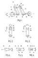
- Figure 1 shows a device coupling 10 according to the invention interposed between a member rotary drive 12 and a driven rotary member 14, which are integral in rotation with respective axes 16 and 18 substantially aligned.
- the organ rotary drive 12 is a control button, while the driven rotary member 14 is a mechanism controlled, by example a potentiometer, an electrical switch, etc.
- the command button 12 is usually centered on a front of a control panel (not shown), while the driven member 14 is placed behind the facade.
- This mechanism makes it possible to make up for "non-coaxiality" because that the two axes 16 and 18 are parallel with a distance not zero and / or that these two axes are not strictly parallel.
- the coupling device 10 of the invention allows to make such a catch-up. It includes a lever 20 (also called index) linked to axis 16 and a slide 22 (also called fork) linked to axis 18. As a variant, the lever 20 could be linked to axis 18 and slide 22 to axis 16.
- connection of the lever 20 with the axis 16 and the connection of the slide 22 with axis 18 are made by any means suitable for there to be a rotation joint. These two connections can be made for example by screwing, press fitting with or without additional means key-type rotary motion transmission, groove, etc.
- the lever 20 extends in the radial direction relative to the axis 16 and it carries, at a distance from the axis, a finger 24 which has an axis XX parallel to the axis 16.
- the finger 24 ( Figures 1 and 4) is shaped general circular cylindrical and it has a diameter exterior D of selected value.
- the slide 22 extends in a radial direction relative to to the axis 18 and it delimits a groove 26 extending in direction substantially radial and placed close to a end 28 of slide 22, opposite its end 30 which is coupled to axis 18.
- the groove 26 has the shape of an oblong slot which crosses the slide 22 in the axial direction.
- This groove 26 has two opposite main faces 32 extending in the direction radial and interconnected by two faces 34 of shape general semi-circular. The two faces 32 are parallel between them and define the width L of the groove.
- the finger 24 is suitable for engaging in the groove 26 for ensure movement transmission between lever 20 and backstage 22.
- the transverse dimension D (which here corresponds to the diameter) of finger 24 and the width L of groove 26 are chosen so that sliding takes place without play.
- the finger 24 is full and the transverse dimension D must be substantially equal to the width L of the slot.
- this device makes it possible to catch up with the lack of co-axiality and also a play in the direction axial. Indeed, in practice, the distance between the lever 20 of slide 22 can vary due to tolerances of manufacturing and assembly.
- the finger 24 has a generally cylindrical shape but is split. he indeed comprises a diametrical slot 36 extending over at minus part of the finger, which defines two deformable lips 38. Note that these two lips 38 slide respectively against the main faces opposite 32 of the groove 26. It is advantageous that the finger has, at the level of the deformable lips 38, a transverse dimension D which is equal or slightly greater than the width L of the groove. In this way, the lips 38 rub elastically against the faces 32 of groove 26, helping to ensure transmission without Game.
- the finger 24 includes a spherical part 40 of transverse dimension D which is provided with a diametrical slot 42 to define two lips 44.
- the transverse dimension D of the finger, at the level of the two lips 44, is advantageously equal or slightly greater than the width L of the slit, as in the case of Figure 5.
- the slide 22 is substantially similar to that of Figure 2, at difference that groove 26 here has a closed end 34 on the side near the axis and an open end 46 of the far side of the axis.
- the lever 20 and the slide 22 are advantageously made by molding a plastic material. It can be beneficial also that the lever and the slide are each time made in one piece with the corresponding axis.
- the rotary drive 12 is a button rotary suitable for being centered in a control panel 48 produced in the form of a housing suitable for being integrated, by example, in a dashboard of a motor vehicle.
- the control panel 48 has a facade 50 delimiting an annular groove 52 for receiving a skirt 54 (FIG. 7) that includes the control button 12. This control button is secured to axis 16 by a self-tapping screw 56.
- the axis 16 is made in one piece with the lever 20 which, in the example, has the shape of a plate carrying the finger 24.
- the slide 22 has the shape of a sector having a circular opening 60 suitable for being coupled in solidarity with the axis 18 of the driven rotary member 14.
- the slide 22 has a groove 26 in which comes engage finger 24. This groove 26 is surrounded by two other similar grooves providing other possibilities of mounting.
- Control panel 48 defines a light pipe suitable for at least partially illuminating the control button 12 and the facade 50, the latter being provided with symbols or appropriate pictograms (not shown) to allow identify the position taken by the rotary drive 12, which forms a control button.
- the control panel 48 has a rear face open 64 ( Figures 7 and 9) into which is embedded an electronic card 66 of generally rectangular shape.
- This electronic card has four openings 68 suitable for being traversed by four 70 screws to allow its mounting at the rear of the control panel.
- the card 66 carries, in its central part, the driven member 14 which, in the example, is a controlled mechanism, such as a potentiometer or switch, which can be controlled by axis 18.
- the driven member 14 which, in the example, is a controlled mechanism, such as a potentiometer or switch, which can be controlled by axis 18.
- the coupling 10 thus makes it possible to make up for a defect in co-axiality possible between axes 16 and 18 and possibly a backlash in the axial direction.
- mechanism 10 ensures simple and effective transmission of movements, between the driving member 12 and the driven member 14.
- the device may include a push type switch, also called “push” type, combined with the driven rotary member 14 and suitable for being actuated by an axial thrust exerted on the axis 16 of the rotating member 12 and transmitted by axial deformation of the coupling device.
- a push type switch also called "push” type
- the axial distance between the lever 20 and the slide 22 at the level of the axis of rotation is very small, or even zero. So when you press the button control 12, the lever 20 presses on the slide 22, which allows to transmit a force in the axial direction and actuate the push switch which is combined with the driven rotary member.
- the device of the invention also offers the advantage additional to be able to be realized with a minimum of parts and be able to operate without play, unlike Oldham type seals which have two orthogonal slides.
- the device of the invention finds a particular application to control panels used in vehicles automobiles.
Landscapes
- Engineering & Computer Science (AREA)
- General Engineering & Computer Science (AREA)
- Mechanical Engineering (AREA)
- Mechanical Control Devices (AREA)
Abstract
Description
- la figure 1 est une vue schématique en perspective éclatée d'un dispositif d'accouplement selon l'invention ;
- la figure 2 est une vue en élévation d'une coulisse selon une forme de réalisation ;
- la figure 3 est une vue en élévation d'une coulisse selon une autre forme de réalisation ;
- les figures 4, 5 et 6 sont des vues d'extrémités du levier pour trois formes de réalisations différentes du doigt ;
- la figure 7 est une vue en perspective éclatée d'un bouton rotatif centré sur un tableau de commande et relié à un mécanisme rotatif d'une carte électronique par l'intermédiaire d'un dispositif d'accouplement selon l'invention ;
- la figure 8 est une vue en perspective par l'avant du tableau de commande ; et
- la figure 9 est une vue en perspective par l'arrière du tableau de commande.
Claims (13)
- Dispositif d'accouplement entre un organe rotatif menant et un organe rotatif mené liés respectivement à deux axes sensiblement alignés,
caractérisé en ce qu'il comprend un levier (20) (encore appelé index) lié à l'un des deux axes (16, 18) et portant un doigt (24) de forme choisie s'étendant parallèlement à l'axe et à distance de lui, ainsi qu'une coulisse (22) (encore appelée fourchette) liée à l'autre des deux axes et comportant au moins une rainure (26) s'étendant dans une direction sensiblement radiale et servant de glissière pour le doigt (24) du levier (20). - Dispositif selon la revendication 1, caractérisé en ce que la rainure (26) a une largeur (L) et le doigt (24) une dimension transversale (D) choisies en sorte que le doigt coulisse sans jeu dans la rainure.
- Dispositif selon l'une des revendications 1 et 2, caractérisé en ce que la rainure (26) comporte deux faces principales opposées (32) parallèles entre elles qui définissent la largeur (L) de la rainure.
- Dispositif selon la revendication 3, caractérisé en ce que le doigt (24) est fendu au moins en partie pour définir deux lèvres déformables (38 ; 44) propres à coulisser respectivement contre les deux faces principales opposées (32) de la rainure (26).
- Dispositif selon la revendication 4, caractérisé en ce que le doigt (24) possède, au niveau des lèvres déformables, une dimension transversale (D) égale ou légèrement supérieure à la largeur (L) de la rainure (26).
- Dispositif selon l'une des revendications 1 à 5, caractérisé en ce que la rainure (26) possède deux extrémités fermées (34, 34).
- Dispositif selon l'une des revendications 1 à 5, caractérisé en ce que la rainure (26) possède une extrémité fermée (34) du côté proche de l'axe et une extrémité ouverte (46) du côté éloigné de l'axe.
- Dispositif selon l'une des revendications 1 à 7, caractérisé en ce que le doigt (24) possède une forme généralement cylindrique.
- Dispositif selon l'une des revendications 1 à 7, caractérisé en ce que le doigt (24) possède une forme généralement sphérique.
- Dispositif selon l'une des revendications 1 à 9, caractérisé en ce que le doigt (24) est en outre propre à coulisser dans la rainure (26) dans la direction axiale.
- Dispositif selon l'une des revendications 1 à 10, caractérisé en ce que le levier (20) et la coulisse (22) sont réalisés par moulage d'une matière plastique.
- Dispositif selon l'une des revendications 1 à 11, caractérisé en ce qu'il comprend un commutateur du type à poussée, ou "push", combiné à l'organe rotatif mené (14) et propre à être actionné par une poussée axiale exercée sur l'axe (16) de l'organe rotatif menant (12) et transmise par déformation axiale du dispositif d'accouplement.
- Dispositif selon l'une des revendications 1 à 12, caractérisé en ce que l'organe rotatif menant (12) est un bouton de commande faisant partie d'un tableau de commande (48), tandis que l'organe rotatif mené (14) est un mécanisme faisant partie d'une carte électronique (66) ou d'une platine surmoulée.
Applications Claiming Priority (2)
| Application Number | Priority Date | Filing Date | Title |
|---|---|---|---|
| FR9916262 | 1999-12-22 | ||
| FR9916262A FR2802994B1 (fr) | 1999-12-22 | 1999-12-22 | Dispositif d'accouplement entre un organe rotatif menant et un organe rotatif mene, en particulier pour tableau de commande |
Publications (2)
| Publication Number | Publication Date |
|---|---|
| EP1111260A1 true EP1111260A1 (fr) | 2001-06-27 |
| EP1111260B1 EP1111260B1 (fr) | 2008-11-05 |
Family
ID=9553641
Family Applications (1)
| Application Number | Title | Priority Date | Filing Date |
|---|---|---|---|
| EP20000127888 Expired - Lifetime EP1111260B1 (fr) | 1999-12-22 | 2000-12-20 | Dispositif d'accouplement entre un organe rotatif menant et un organe rotatif mené, en particulier pour tableau de commande |
Country Status (3)
| Country | Link |
|---|---|
| EP (1) | EP1111260B1 (fr) |
| DE (1) | DE60040718D1 (fr) |
| FR (1) | FR2802994B1 (fr) |
Citations (4)
| Publication number | Priority date | Publication date | Assignee | Title |
|---|---|---|---|---|
| GB794265A (en) * | 1955-05-16 | 1958-04-30 | Donald Brown Brownall Ltd | Improvements relating to connections for operating rotary valves or cocks |
| US3117431A (en) * | 1961-08-09 | 1964-01-14 | Western Electric Co | Universal joint |
| FR1395032A (fr) * | 1964-02-28 | 1965-04-09 | Radiotechnique | Dispositif de couplage en rotation à engagement et dégagement instantanés |
| US4790795A (en) * | 1985-03-26 | 1988-12-13 | Aisin Seiki Kabushiki Kaisha | Connection construction of turning angle detector |
-
1999
- 1999-12-22 FR FR9916262A patent/FR2802994B1/fr not_active Expired - Lifetime
-
2000
- 2000-12-20 DE DE60040718T patent/DE60040718D1/de not_active Expired - Lifetime
- 2000-12-20 EP EP20000127888 patent/EP1111260B1/fr not_active Expired - Lifetime
Patent Citations (4)
| Publication number | Priority date | Publication date | Assignee | Title |
|---|---|---|---|---|
| GB794265A (en) * | 1955-05-16 | 1958-04-30 | Donald Brown Brownall Ltd | Improvements relating to connections for operating rotary valves or cocks |
| US3117431A (en) * | 1961-08-09 | 1964-01-14 | Western Electric Co | Universal joint |
| FR1395032A (fr) * | 1964-02-28 | 1965-04-09 | Radiotechnique | Dispositif de couplage en rotation à engagement et dégagement instantanés |
| US4790795A (en) * | 1985-03-26 | 1988-12-13 | Aisin Seiki Kabushiki Kaisha | Connection construction of turning angle detector |
Also Published As
| Publication number | Publication date |
|---|---|
| FR2802994A1 (fr) | 2001-06-29 |
| FR2802994B1 (fr) | 2002-04-26 |
| DE60040718D1 (de) | 2008-12-18 |
| EP1111260B1 (fr) | 2008-11-05 |
Similar Documents
| Publication | Publication Date | Title |
|---|---|---|
| EP0792779B1 (fr) | Motoréducteur, notamment pour l'entraínement de bras d'essuie-glace dans un véhicule automobile | |
| FR2817212A1 (fr) | Lampe de vehicule et appareil d'entrainement en rotation d'un dispositif optique | |
| FR2838169A1 (fr) | Systeme de debrayage pour un mecanisme a deux embrayages pour vehicule automobile. | |
| FR2764358A1 (fr) | Dispositif pour actionner un arbre de commutation d'une boite de vitesses | |
| EP1234936A1 (fr) | Serrure d'ouvrant de véhicule automobile à maneton débrayable | |
| WO2022128987A1 (fr) | Volant de vehicule automobile a jante repliable ou escamotable | |
| EP1111260B1 (fr) | Dispositif d'accouplement entre un organe rotatif menant et un organe rotatif mené, en particulier pour tableau de commande | |
| FR2859050A1 (fr) | Unite d'entrainement et de transmission comportant au moins deux moteurs pour actionner ou deplacer une piece equipant un vehicule automobile | |
| EP1420181B1 (fr) | Système de retenue en translation de deux pièces rotatives et procédé de montage de ces deux pièces | |
| EP2612049B1 (fr) | Dispositif de transmission de couple | |
| FR2784148A1 (fr) | Dispositif d'accouplement entre un bouton de commande et un mecanisme | |
| EP1111259B1 (fr) | Dispositif d'accouplement entre un organe rotatif menant et un organe rotatif mené | |
| EP1941118B1 (fr) | Dispositif d'ouverture de vitre arriere et/ou coffre de vehicule | |
| EP1660843A1 (fr) | Actionneur universel notamment pour application aux tableaux de bord | |
| EP1508728B1 (fr) | Dispositf de changement de vitesse, ensemble et véhicule automobile correspondants | |
| FR2538139A1 (fr) | Organe ou dispositif de commande manuelle pour entrainements de positionnement sur les vehicules automobiles | |
| FR2862366A1 (fr) | Dispositif de commande d'un rapport d'une boite de vitesses. | |
| FR2836730A1 (fr) | Tableau de commande a boutons coaxiaux pour installation de traitement d'air de vehicule | |
| FR2812446A1 (fr) | Interrupteur non reversible de retour a la position de repos d'un moteur d'essuie-glace | |
| FR2708061A1 (fr) | Système d'accouplement à rattrapage de jeu entre deux pièces d'axes parallèles. | |
| EP0843248B1 (fr) | Système d'activation débrayable d'un organe fonctionnel de véhicule automobile | |
| FR3145589A1 (fr) | Actionneur électromécanique | |
| WO2023208996A1 (fr) | Dispositif de selection;boîte de vitesses; | |
| EP1129311A1 (fr) | Agencement pour l'entrainement d'un axe de commande d'une boite de vitesses | |
| EP2651693B1 (fr) | Module de commande sous-volant |
Legal Events
| Date | Code | Title | Description |
|---|---|---|---|
| PUAI | Public reference made under article 153(3) epc to a published international application that has entered the european phase |
Free format text: ORIGINAL CODE: 0009012 |
|
| AK | Designated contracting states |
Kind code of ref document: A1 Designated state(s): DE ES GB IT |
|
| AX | Request for extension of the european patent |
Free format text: AL;LT;LV;MK;RO;SI |
|
| 17P | Request for examination filed |
Effective date: 20011214 |
|
| AKX | Designation fees paid |
Free format text: DE ES GB IT |
|
| 17Q | First examination report despatched |
Effective date: 20050628 |
|
| GRAP | Despatch of communication of intention to grant a patent |
Free format text: ORIGINAL CODE: EPIDOSNIGR1 |
|
| RIN1 | Information on inventor provided before grant (corrected) |
Inventor name: GUILBAULT, GAETAN Inventor name: BOMBARD STEPHANE Inventor name: KORZENIEWSKI, ULRICH |
|
| RTI1 | Title (correction) |
Free format text: COUPLING ARRANGEMENT BETWEEN AN INPUT AND OUTPUT ROTARY MEMBER, ESPECIALLY FOR A CONTROL PANEL |
|
| GRAS | Grant fee paid |
Free format text: ORIGINAL CODE: EPIDOSNIGR3 |
|
| GRAA | (expected) grant |
Free format text: ORIGINAL CODE: 0009210 |
|
| AK | Designated contracting states |
Kind code of ref document: B1 Designated state(s): DE ES GB IT |
|
| REG | Reference to a national code |
Ref country code: GB Ref legal event code: FG4D Free format text: NOT ENGLISH |
|
| REF | Corresponds to: |
Ref document number: 60040718 Country of ref document: DE Date of ref document: 20081218 Kind code of ref document: P |
|
| PG25 | Lapsed in a contracting state [announced via postgrant information from national office to epo] |
Ref country code: ES Free format text: LAPSE BECAUSE OF FAILURE TO SUBMIT A TRANSLATION OF THE DESCRIPTION OR TO PAY THE FEE WITHIN THE PRESCRIBED TIME-LIMIT Effective date: 20090216 |
|
| PLBE | No opposition filed within time limit |
Free format text: ORIGINAL CODE: 0009261 |
|
| STAA | Information on the status of an ep patent application or granted ep patent |
Free format text: STATUS: NO OPPOSITION FILED WITHIN TIME LIMIT |
|
| 26N | No opposition filed |
Effective date: 20090806 |
|
| PGFP | Annual fee paid to national office [announced via postgrant information from national office to epo] |
Ref country code: DE Payment date: 20171212 Year of fee payment: 18 |
|
| PGFP | Annual fee paid to national office [announced via postgrant information from national office to epo] |
Ref country code: GB Payment date: 20171219 Year of fee payment: 18 Ref country code: IT Payment date: 20171213 Year of fee payment: 18 |
|
| REG | Reference to a national code |
Ref country code: DE Ref legal event code: R119 Ref document number: 60040718 Country of ref document: DE |
|
| GBPC | Gb: european patent ceased through non-payment of renewal fee |
Effective date: 20181220 |
|
| PG25 | Lapsed in a contracting state [announced via postgrant information from national office to epo] |
Ref country code: DE Free format text: LAPSE BECAUSE OF NON-PAYMENT OF DUE FEES Effective date: 20190702 Ref country code: IT Free format text: LAPSE BECAUSE OF NON-PAYMENT OF DUE FEES Effective date: 20181220 |
|
| PG25 | Lapsed in a contracting state [announced via postgrant information from national office to epo] |
Ref country code: GB Free format text: LAPSE BECAUSE OF NON-PAYMENT OF DUE FEES Effective date: 20181220 |