EP1110849A1 - Vehicle frame reinforcement - Google Patents
Vehicle frame reinforcement Download PDFInfo
- Publication number
- EP1110849A1 EP1110849A1 EP00124744A EP00124744A EP1110849A1 EP 1110849 A1 EP1110849 A1 EP 1110849A1 EP 00124744 A EP00124744 A EP 00124744A EP 00124744 A EP00124744 A EP 00124744A EP 1110849 A1 EP1110849 A1 EP 1110849A1
- Authority
- EP
- European Patent Office
- Prior art keywords
- side frame
- frame member
- reinforcement
- vehicle
- section
- Prior art date
- Legal status (The legal status is an assumption and is not a legal conclusion. Google has not performed a legal analysis and makes no representation as to the accuracy of the status listed.)
- Granted
Links
Images



Classifications
-
- B—PERFORMING OPERATIONS; TRANSPORTING
- B62—LAND VEHICLES FOR TRAVELLING OTHERWISE THAN ON RAILS
- B62D—MOTOR VEHICLES; TRAILERS
- B62D21/00—Understructures, i.e. chassis frame on which a vehicle body may be mounted
-
- B—PERFORMING OPERATIONS; TRANSPORTING
- B62—LAND VEHICLES FOR TRAVELLING OTHERWISE THAN ON RAILS
- B62D—MOTOR VEHICLES; TRAILERS
- B62D21/00—Understructures, i.e. chassis frame on which a vehicle body may be mounted
- B62D21/15—Understructures, i.e. chassis frame on which a vehicle body may be mounted having impact absorbing means, e.g. a frame designed to permanently or temporarily change shape or dimension upon impact with another body
- B62D21/152—Front or rear frames
-
- B—PERFORMING OPERATIONS; TRANSPORTING
- B62—LAND VEHICLES FOR TRAVELLING OTHERWISE THAN ON RAILS
- B62D—MOTOR VEHICLES; TRAILERS
- B62D21/00—Understructures, i.e. chassis frame on which a vehicle body may be mounted
- B62D21/02—Understructures, i.e. chassis frame on which a vehicle body may be mounted comprising longitudinally or transversely arranged frame members
-
- B—PERFORMING OPERATIONS; TRANSPORTING
- B62—LAND VEHICLES FOR TRAVELLING OTHERWISE THAN ON RAILS
- B62D—MOTOR VEHICLES; TRAILERS
- B62D25/00—Superstructure or monocoque structure sub-units; Parts or details thereof not otherwise provided for
- B62D25/08—Front or rear portions
Definitions
- the present invention relates to a reinforcement of a vehicle frame structure, more particularly to a reinforcement for minimizing interference with other components to be installed around the frames and for reinforcing the weakened portions on a side frame member in a motor vehicle frame structure.
- the motor vehicles are provided with a pair of lateral side frame members which extend in a lateral direction of the vehicle.
- Each of the two side frame members is connected by at least one cross frame member.
- Reinforcement and bumper or the like is engaged by securing elements such as rivets, bolts or welding to the side frame member.
- the frame structure is referred to H-shaped frame because of the outline of the frame members.
- the side frame member functions to support load, and absorb, deliver rearward and disperse impact load when a sudden impact force is imposed on the vehicle from a collision.
- the cross section of side frame member is in a rectangular shape.
- a kick-up frame is bent so as to lower the underside panel of the vehicle, i.e., passenger cars and buses.
- FIG. 1 is a side view of the general frame structure of the vehicle.
- a typical frame structure 10 for the vehicle is provided with a pair of side frame members 11 in a lateral direction and at least one cross frame member 12 for connecting the side frame member 11 at a predetermined position thereof.
- a kick-up frame 13 which is bent to lower the underside panel of the vehicle is connected in itself.
- Japanese Patent Laid-open Publication No. (Pyung) 8-58616 discloses a bumper stay for reinforcing the side frame member, as shown in FIG. 4.
- the bumper stay C in a stair-shape in cross section is formed as a reinforcing means for reinforcing an interconnection of the side frame member A with the cross frame member B which is transversely disposed on the side frame member A.
- the bumper stay C is secured to the side frame member A and the cross member B via bolts, respectively.
- the conventional side frame member A of the vehicle includes the reinforcement installed to the side frame member A for reinforcing the side frame member A itself or the bumper stay C secured at the interconnection of the side frame member A with the cross frame member B, section modulus or reinforcing effect is not improved.
- the conventional frame members have a disadvantage that the impact is concentrated on the kick-up frame 13, thereby causing a driver and/or passengers to be exposed to a severe injury by the impact.
- a pair of laterally extending side frame members 11 disposed on each side of a vehicle body and at least one cross frame member 12 disposed between the side frame members 11.
- the side frame members 11 are provided with the kick-up frames 13, each integrally and inwardly bent formed at one end of the side frame member 11.
- the present invention further comprises a reinforcement 30 installed at the interconnection of the side frame member 11 with the kick-up frame 13.
- the reinforcement 30 does not interfere with any pipes or components in the exhaust system.
- the reinforcement 30 prevents the passenger compartment of the vehicle from deforming or buckling, so that a driver and/or passengers may secure a security space despite collision, thereby improving security and reliability of the vehicle.
- FIG. 1 shows a general frame structure.
- the frame structure comprises a pair of side frame members 11 extending in the lateral direction of the vehicle, each of which is connected by at least one cross member 12 at a predetermined position thereof, a kick-up frame 13 integrally formed of bent portion with the side frame member 11, and a reinforcement 30 installed at the interconnection of the side frame member 11 with the kick-up frame 13.
- the reinforcement 30, hollow and triangular in cross section includes a flat top section 20 in parallel to a top section of the side frame member 11 and a slope section 21 which is inclined downwardly and formed integrally therewith.
- the end of the flat top section 20 and the end of the slope section 21 have flanges 22, 23 thereof, respectively, so that the top section 20 and the slope section 21 may be fixed and welded to be in contact with upper and lower portions of the side frame member 11.
- the reinforcement 30 is installed in the kick-up frame 13 of the side frame member 11, as shown in FIG. 2.
- an unimpaired square pipe may be utilized or two channel members in the shape of a bracket extending both ends, i.e., "[" in opposite for engagement in the lateral direction are utilized as in FIG. 2.
- the pipes 31 e.g., a fuel pipe and a brake pipe are preferably positioned above the reinforcement 30.
- the exhaust system components 40 are positioned at a predetermined distance from the outer surface of the slope section 21 of the reinforcement 30, since the exhaust system components 40 are maintained at a high temperature by heat from the exhaust gas of the engine.
- FIG. 3 is a perspective view of a preferred embodiment of the frame structure to which reinforcements are installed according to the present invention.
- the vehicle frame structure 10 comprises a pair of lateral side frame members 11 which extend in the lateral direction of the vehicle.
- Each of the two side frame members 11 is connected by at least one cross member 12 at a predetermined position.
- the kick-up frame 13 is bent to lower the underside panel of the vehicle, which is connected in integral with the side frame member 11.
- the reinforcement 30 is installed along the kick-up frame 13 and the interconnection of the side frame member 11 therewith for reinforcing the weakened portion of the side frame member 11 in the event of a collision.
- the reinforcement 30 having a large section modulus thereof effectively reinforces the vehicle frame 10, thereby preventing the deformation of the passenger compartment of the vehicle despite collision and accommodating a driver and/or passengers to secure a security space.
- the present invention avoids interference with the exhaust system components and the pipes passing in the lateral direction of the vehicle, so that the vehicle pipes such as a fuel pipe or a brake pipe block the heat emitted from the exhaust system components, to guarantee piping security.
- the present invention improves security and reliability of the vehicle.
Landscapes
- Engineering & Computer Science (AREA)
- Chemical & Material Sciences (AREA)
- Combustion & Propulsion (AREA)
- Transportation (AREA)
- Mechanical Engineering (AREA)
- Body Structure For Vehicles (AREA)
Abstract
Description
- The present invention relates to a reinforcement of a vehicle frame structure, more particularly to a reinforcement for minimizing interference with other components to be installed around the frames and for reinforcing the weakened portions on a side frame member in a motor vehicle frame structure.
- Generally, the motor vehicles are provided with a pair of lateral side frame members which extend in a lateral direction of the vehicle. Each of the two side frame members is connected by at least one cross frame member. Reinforcement and bumper or the like is engaged by securing elements such as rivets, bolts or welding to the side frame member. The frame structure is referred to H-shaped frame because of the outline of the frame members.
- The side frame member functions to support load, and absorb, deliver rearward and disperse impact load when a sudden impact force is imposed on the vehicle from a collision.
- The cross section of side frame member is in a rectangular shape. A kick-up frame is bent so as to lower the underside panel of the vehicle, i.e., passenger cars and buses.
- FIG. 1 is a side view of the general frame structure of the vehicle. A
typical frame structure 10 for the vehicle is provided with a pair ofside frame members 11 in a lateral direction and at least onecross frame member 12 for connecting theside frame member 11 at a predetermined position thereof. At one end of theside frame member 11, a kick-upframe 13 which is bent to lower the underside panel of the vehicle is connected in itself. - In this frame structure, when a collision of the vehicle occurs, an abrupt impact load is delivered on the
side frame member 11 from a bumper (not shown) and absorbed by deformation of theside frame member 11. However, at the time of collision, the impact load is concentrated on the kick-upframe 13 and serious deformation of the kick-up frame 13 results in a severe injury of a driver and/or passengers by the impact. - Japanese Patent Laid-open Publication No. (Pyung) 8-58616 discloses a bumper stay for reinforcing the side frame member, as shown in FIG. 4.
- In FIG. 4, the bumper stay C in a stair-shape in cross section, is formed as a reinforcing means for reinforcing an interconnection of the side frame member A with the cross frame member B which is transversely disposed on the side frame member A. The bumper stay C is secured to the side frame member A and the cross member B via bolts, respectively.
- Although the conventional side frame member A of the vehicle includes the reinforcement installed to the side frame member A for reinforcing the side frame member A itself or the bumper stay C secured at the interconnection of the side frame member A with the cross frame member B, section modulus or reinforcing effect is not improved.
- As a result, the conventional frame members have a disadvantage that the impact is concentrated on the kick-up
frame 13, thereby causing a driver and/or passengers to be exposed to a severe injury by the impact. - It is therefore an object of the present invention to provide a reinforcement disposed on the kick-up frame of the side frame member, which prevents a passenger compartment of the vehicle from deforming or buckling, so that a driver and/or passengers may secure a security space despite collision.
- It is the other object of the present invention to provide a reinforcement for absorbing impact applied thereto, which increases section modulus thereof to effectively reinforce the side frame member and eliminates interference in the assembly process of a fuel pipe and an exhaust pipe or the like.
- In order to accomplish the above objects, there are provided a pair of laterally extending
side frame members 11 disposed on each side of a vehicle body and at least onecross frame member 12 disposed between theside frame members 11. Theside frame members 11 are provided with the kick-up frames 13, each integrally and inwardly bent formed at one end of theside frame member 11. The present invention further comprises areinforcement 30 installed at the interconnection of theside frame member 11 with the kick-up frame 13. - The
reinforcement 30 does not interfere with any pipes or components in the exhaust system. - Additionally, the
reinforcement 30 prevents the passenger compartment of the vehicle from deforming or buckling, so that a driver and/or passengers may secure a security space despite collision, thereby improving security and reliability of the vehicle. - The above and other objects and features of the present invention may be understood with reference to the following detailed description of an illustrative embodiment of the invention, taken together with the accompanying drawings in which:
- FIG. 1 is a side view of a general frame structure of the vehicle;
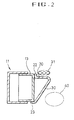
- FIG. 2 is a sectional view of a preferred embodiment of the frame structure to which reinforcements are installed according to the present invention;
- FIG. 3 is a perspective view of a preferred embodiment of the frame structure to which reinforcements are installed according to the present invention; and
- FIG. 4 is a sectional view of the bumper stay according to the conventional frame structure.
-
- FIG. 1 shows a general frame structure. The frame structure comprises a pair of
side frame members 11 extending in the lateral direction of the vehicle, each of which is connected by at least onecross member 12 at a predetermined position thereof, a kick-upframe 13 integrally formed of bent portion with theside frame member 11, and areinforcement 30 installed at the interconnection of theside frame member 11 with the kick-up frame 13. - Referring to FIG. 2, the
reinforcement 30, hollow and triangular in cross section, includes aflat top section 20 in parallel to a top section of theside frame member 11 and a slope section 21 which is inclined downwardly and formed integrally therewith. - The end of the
flat top section 20 and the end of the slope section 21 haveflanges top section 20 and the slope section 21 may be fixed and welded to be in contact with upper and lower portions of theside frame member 11. - Accordingly, the
reinforcement 30 is installed in the kick-upframe 13 of theside frame member 11, as shown in FIG. 2. - For the
side frame member 11, an unimpaired square pipe may be utilized or two channel members in the shape of a bracket extending both ends, i.e., "[" in opposite for engagement in the lateral direction are utilized as in FIG. 2. - When the
reinforcement 30 is installed at the interconnection of theside frame member 11 with the kick-upframe 13, thepipes 31 e.g., a fuel pipe and a brake pipe are preferably positioned above thereinforcement 30. - Then, the
exhaust system components 40 are positioned at a predetermined distance from the outer surface of the slope section 21 of thereinforcement 30, since theexhaust system components 40 are maintained at a high temperature by heat from the exhaust gas of the engine. - FIG. 3 is a perspective view of a preferred embodiment of the frame structure to which reinforcements are installed according to the present invention.
- As shown is in FIG. 3, the
vehicle frame structure 10 comprises a pair of lateralside frame members 11 which extend in the lateral direction of the vehicle. Each of the twoside frame members 11 is connected by at least onecross member 12 at a predetermined position. The kick-upframe 13 is bent to lower the underside panel of the vehicle, which is connected in integral with theside frame member 11. - According to the present invention, the
reinforcement 30 is installed along the kick-upframe 13 and the interconnection of theside frame member 11 therewith for reinforcing the weakened portion of theside frame member 11 in the event of a collision. - Accordingly, the
reinforcement 30 having a large section modulus thereof effectively reinforces thevehicle frame 10, thereby preventing the deformation of the passenger compartment of the vehicle despite collision and accommodating a driver and/or passengers to secure a security space. - Additionally, the present invention avoids interference with the exhaust system components and the pipes passing in the lateral direction of the vehicle, so that the vehicle pipes such as a fuel pipe or a brake pipe block the heat emitted from the exhaust system components, to guarantee piping security. The present invention improves security and reliability of the vehicle.
- The present invention is not limited to these embodiments, and it should be clear to those skilled in the art that other embodiments are possible within the spirit and scope of the invention claimed.
Claims (3)
- Reinforcement for reinforcing a vehicle frame structure (10) including a pair of lateral side frame members (11) extending in a lateral direction of the vehicle, and at least one cross frame member (12) connecting the side frame members (11) at a predetermined position of the side frame member (11), each of the side frame members (11) having a kick-up frame (13) inwardly bent at the end thereof, characterized in that the reinforcement (30) is installed at the interconnection of the side frame member (11) with the kick-up frame (13) of the side frame member (11).
- Reinforcement according to claim 1, wherein said reinforcement (30) has a flat top section (20) in parallel to a top section of the side frame member (11) and a slope section (21) which is inclined downwardly having a hollow, triangular shape.
- Reinforcement according to claim 2, wherein said top section (20) and said slope section (21) include flanges (22, 23) integrally curved at the end thereof so that top section (20) and the slope section (21) may be fixed and welded to be in contact with upper and lower portions of the side frame member (11).
Applications Claiming Priority (2)
| Application Number | Priority Date | Filing Date | Title |
|---|---|---|---|
| KR9960005 | 1999-12-21 | ||
| KR1019990060005A KR100333889B1 (en) | 1999-12-21 | 1999-12-21 | Reinforcement structure having a member for reinforcing a frame for a motor vehicle |
Publications (2)
| Publication Number | Publication Date |
|---|---|
| EP1110849A1 true EP1110849A1 (en) | 2001-06-27 |
| EP1110849B1 EP1110849B1 (en) | 2004-03-24 |
Family
ID=19627807
Family Applications (1)
| Application Number | Title | Priority Date | Filing Date |
|---|---|---|---|
| EP00124744A Expired - Lifetime EP1110849B1 (en) | 1999-12-21 | 2000-11-13 | Vehicle frame with reinforcement |
Country Status (7)
| Country | Link |
|---|---|
| US (1) | US6354654B2 (en) |
| EP (1) | EP1110849B1 (en) |
| JP (1) | JP3605669B2 (en) |
| KR (1) | KR100333889B1 (en) |
| CN (1) | CN1147409C (en) |
| DE (1) | DE60009245T2 (en) |
| ID (1) | ID29169A (en) |
Families Citing this family (22)
| Publication number | Priority date | Publication date | Assignee | Title |
|---|---|---|---|---|
| US6588189B2 (en) * | 2001-01-09 | 2003-07-08 | Case Corporation | Compound bend chassis frame for a harvesting machine |
| US6712392B2 (en) * | 2002-06-05 | 2004-03-30 | Ford Global Technologies, Llc | Automotive frame assembly |
| JP4011028B2 (en) * | 2004-02-26 | 2007-11-21 | ダイハツ工業株式会社 | Vehicle front structure |
| JP4581517B2 (en) * | 2004-07-08 | 2010-11-17 | マツダ株式会社 | Lower body structure of the vehicle |
| US7699346B2 (en) * | 2005-03-23 | 2010-04-20 | Chrysler Group Llc | Force redistributing system for a vehicle in the event of a rear impact |
| KR100689293B1 (en) * | 2005-07-25 | 2007-03-02 | 볼보 컨스트럭션 이키프먼트 홀딩 스웨덴 에이비 | Upper frame structure supporting the cab of the construction machine |
| JP5044288B2 (en) * | 2007-05-28 | 2012-10-10 | トヨタ自動車株式会社 | Mount bracket connection structure |
| KR20090023760A (en) * | 2007-09-03 | 2009-03-06 | 현대자동차주식회사 | Chassis frame of fuel cell vehicle |
| JP2009234495A (en) * | 2008-03-28 | 2009-10-15 | Mazda Motor Corp | Frame structure of automobile |
| US7862105B2 (en) * | 2009-02-20 | 2011-01-04 | Gm Global Technology Operations, Inc. | Motor compartment rail assembly with stability enhancement member |
| CN102452420B (en) * | 2010-10-21 | 2015-07-08 | 上海申龙客车有限公司 | Half-bearing frame with rectangular pipe welding structure |
| DE102010052794B4 (en) * | 2010-11-27 | 2021-12-16 | Volkswagen Aktiengesellschaft | Device for improving occupant protection in a vehicle |
| JP5724752B2 (en) * | 2011-08-24 | 2015-05-27 | トヨタ車体株式会社 | Kick-up frame connection structure |
| US8398152B1 (en) | 2011-10-05 | 2013-03-19 | GM Global Technology Operations LLC | Multi-cell motor compartment rail |
| CN102901318B (en) * | 2012-11-13 | 2016-03-30 | 合肥美的电冰箱有限公司 | Rack supports frame and there is its refrigerator |
| CN103192880A (en) * | 2013-04-28 | 2013-07-10 | 长城汽车股份有限公司 | Vehicle and frame thereof |
| KR101703596B1 (en) * | 2015-07-24 | 2017-02-07 | 현대자동차 주식회사 | Front vehicle body structure |
| CN107187500A (en) * | 2017-05-23 | 2017-09-22 | 保定中兴田野新能源汽车科技有限公司 | A kind of three-dimensional multipath bearing-type engine room structure |
| US10214243B2 (en) | 2017-07-11 | 2019-02-26 | Ford Global Technologies, Llc | Vehicle frame |
| CN108001533A (en) * | 2017-11-22 | 2018-05-08 | 奇瑞汽车股份有限公司 | Front deck vehicle frame |
| CN109353412B (en) * | 2018-09-13 | 2020-11-17 | 吉利汽车研究院(宁波)有限公司 | Front collision energy-absorbing device and vehicle body assembly with same |
| JP7587944B2 (en) * | 2020-09-03 | 2024-11-21 | プレス工業株式会社 | Vehicle body frame member and method for manufacturing vehicle body frame member |
Citations (3)
| Publication number | Priority date | Publication date | Assignee | Title |
|---|---|---|---|---|
| EP0421277A1 (en) * | 1989-09-30 | 1991-04-10 | Mazda Motor Corporation | Front body structure of automotive vehicle |
| US5381871A (en) * | 1991-03-30 | 1995-01-17 | Mazda Motor Corporation | Automotive rear body structure |
| US5713625A (en) * | 1994-10-17 | 1998-02-03 | Honda Giken Kogyo Kabushiki Kaisha | Body structure of motorcar |
Family Cites Families (5)
| Publication number | Priority date | Publication date | Assignee | Title |
|---|---|---|---|---|
| US2202859A (en) * | 1937-12-06 | 1940-06-04 | Budd Edward G Mfg Co | Combined body and chassis underframe |
| DE976332C (en) * | 1940-08-02 | 1963-07-04 | Budd Co | Vehicle subframes, in particular combined chassis and car body subframes |
| EP0435197B1 (en) * | 1989-12-25 | 1994-11-23 | Mazda Motor Corporation | Rear body structure of automotive vehicle |
| US5839776A (en) * | 1993-02-22 | 1998-11-24 | Norsk Hydro A.S. | Structual sub-assembly |
| JP3181792B2 (en) | 1994-08-24 | 2001-07-03 | ダイハツ工業株式会社 | Connection structure between the side frame and cross member of the vehicle body |
-
1999
- 1999-12-21 KR KR1019990060005A patent/KR100333889B1/en not_active Expired - Fee Related
-
2000
- 2000-11-09 ID IDP20000957D patent/ID29169A/en unknown
- 2000-11-10 JP JP2000344327A patent/JP3605669B2/en not_active Expired - Fee Related
- 2000-11-13 EP EP00124744A patent/EP1110849B1/en not_active Expired - Lifetime
- 2000-11-13 DE DE60009245T patent/DE60009245T2/en not_active Expired - Lifetime
- 2000-11-30 US US09/727,797 patent/US6354654B2/en not_active Expired - Lifetime
- 2000-12-01 CN CNB00134451XA patent/CN1147409C/en not_active Expired - Fee Related
Patent Citations (3)
| Publication number | Priority date | Publication date | Assignee | Title |
|---|---|---|---|---|
| EP0421277A1 (en) * | 1989-09-30 | 1991-04-10 | Mazda Motor Corporation | Front body structure of automotive vehicle |
| US5381871A (en) * | 1991-03-30 | 1995-01-17 | Mazda Motor Corporation | Automotive rear body structure |
| US5713625A (en) * | 1994-10-17 | 1998-02-03 | Honda Giken Kogyo Kabushiki Kaisha | Body structure of motorcar |
Also Published As
| Publication number | Publication date |
|---|---|
| JP3605669B2 (en) | 2004-12-22 |
| US6354654B2 (en) | 2002-03-12 |
| US20010004160A1 (en) | 2001-06-21 |
| ID29169A (en) | 2001-08-09 |
| KR20010063128A (en) | 2001-07-09 |
| DE60009245D1 (en) | 2004-04-29 |
| EP1110849B1 (en) | 2004-03-24 |
| KR100333889B1 (en) | 2002-04-25 |
| CN1147409C (en) | 2004-04-28 |
| JP2001180516A (en) | 2001-07-03 |
| DE60009245T2 (en) | 2005-03-10 |
| CN1300677A (en) | 2001-06-27 |
Similar Documents
| Publication | Publication Date | Title |
|---|---|---|
| US6354654B2 (en) | Vehicle frame reinforcement | |
| KR100330953B1 (en) | Front portion structure of an automobile vehicle body | |
| US6604781B2 (en) | Vehicle body structure | |
| CN101332837B (en) | Vehicle body structure | |
| US11084533B2 (en) | Vehicle body structure of vehicle | |
| JP3045337B2 (en) | Car front structure | |
| JP4299899B2 (en) | Auto body floor structure | |
| JP3138175B2 (en) | Rear body structure of vehicle | |
| US6648400B2 (en) | Rear vehicle body structure for pickup trucks | |
| CN220349808U (en) | Battery pack installation structure and vehicle | |
| JP2001130450A (en) | Car body front structure | |
| JP4124333B2 (en) | Reinforcement structure of front hook support in automobile | |
| CN222819941U (en) | Seat mounting structure and vehicle | |
| KR200216709Y1 (en) | Rear floor panel of car | |
| JPH0517348Y2 (en) | ||
| KR200236878Y1 (en) | Reinforcement structure of torsion bar for automobile | |
| JPH11291952A (en) | Body structure | |
| JPS6335904Y2 (en) | ||
| WO2026028236A1 (en) | Automotive front body structure | |
| JP2002316666A (en) | Body front structure | |
| JP2005306103A (en) | Roll bar structure for vehicles | |
| JPS61282143A (en) | Construction of reinforcing anchor part of seat belt for car | |
| KR0132798Y1 (en) | Reinforcement to prevent deformation of floor panels of automobiles | |
| JP3569601B2 (en) | Vehicle door structure | |
| KR100333882B1 (en) | Reinforcement structure having a member for reinforcing frame for a motor vehicle |
Legal Events
| Date | Code | Title | Description |
|---|---|---|---|
| PUAI | Public reference made under article 153(3) epc to a published international application that has entered the european phase |
Free format text: ORIGINAL CODE: 0009012 |
|
| AK | Designated contracting states |
Kind code of ref document: A1 Designated state(s): DE FR GB |
|
| AX | Request for extension of the european patent |
Free format text: AL;LT;LV;MK;RO;SI |
|
| 17P | Request for examination filed |
Effective date: 20011220 |
|
| AKX | Designation fees paid |
Free format text: DE FR GB |
|
| 17Q | First examination report despatched |
Effective date: 20030402 |
|
| GRAP | Despatch of communication of intention to grant a patent |
Free format text: ORIGINAL CODE: EPIDOSNIGR1 |
|
| RTI1 | Title (correction) |
Free format text: VEHICLE FRAME WITH REINFORCEMENT |
|
| RTI1 | Title (correction) |
Free format text: VEHICLE FRAME WITH REINFORCEMENT |
|
| RTI1 | Title (correction) |
Free format text: VEHICLE FRAME WITH REINFORCEMENT |
|
| GRAS | Grant fee paid |
Free format text: ORIGINAL CODE: EPIDOSNIGR3 |
|
| GRAA | (expected) grant |
Free format text: ORIGINAL CODE: 0009210 |
|
| AK | Designated contracting states |
Kind code of ref document: B1 Designated state(s): DE FR GB |
|
| REG | Reference to a national code |
Ref country code: GB Ref legal event code: FG4D |
|
| REF | Corresponds to: |
Ref document number: 60009245 Country of ref document: DE Date of ref document: 20040429 Kind code of ref document: P |
|
| ET | Fr: translation filed | ||
| PLBE | No opposition filed within time limit |
Free format text: ORIGINAL CODE: 0009261 |
|
| STAA | Information on the status of an ep patent application or granted ep patent |
Free format text: STATUS: NO OPPOSITION FILED WITHIN TIME LIMIT |
|
| 26N | No opposition filed |
Effective date: 20041228 |
|
| PGFP | Annual fee paid to national office [announced via postgrant information from national office to epo] |
Ref country code: DE Payment date: 20091105 Year of fee payment: 10 |
|
| PGFP | Annual fee paid to national office [announced via postgrant information from national office to epo] |
Ref country code: GB Payment date: 20091111 Year of fee payment: 10 Ref country code: FR Payment date: 20091123 Year of fee payment: 10 |
|
| GBPC | Gb: european patent ceased through non-payment of renewal fee |
Effective date: 20101113 |
|
| REG | Reference to a national code |
Ref country code: FR Ref legal event code: ST Effective date: 20110801 |
|
| REG | Reference to a national code |
Ref country code: DE Ref legal event code: R119 Ref document number: 60009245 Country of ref document: DE Effective date: 20110601 Ref country code: DE Ref legal event code: R119 Ref document number: 60009245 Country of ref document: DE Effective date: 20110531 |
|
| PG25 | Lapsed in a contracting state [announced via postgrant information from national office to epo] |
Ref country code: DE Free format text: LAPSE BECAUSE OF NON-PAYMENT OF DUE FEES Effective date: 20110531 |
|
| PG25 | Lapsed in a contracting state [announced via postgrant information from national office to epo] |
Ref country code: FR Free format text: LAPSE BECAUSE OF NON-PAYMENT OF DUE FEES Effective date: 20101130 |
|
| PG25 | Lapsed in a contracting state [announced via postgrant information from national office to epo] |
Ref country code: GB Free format text: LAPSE BECAUSE OF NON-PAYMENT OF DUE FEES Effective date: 20101113 |