EP1110826A1 - Pyrotechnische Sicherheitsvorrichtung für ein Kraftfahrzeug - Google Patents
Pyrotechnische Sicherheitsvorrichtung für ein Kraftfahrzeug Download PDFInfo
- Publication number
- EP1110826A1 EP1110826A1 EP00403534A EP00403534A EP1110826A1 EP 1110826 A1 EP1110826 A1 EP 1110826A1 EP 00403534 A EP00403534 A EP 00403534A EP 00403534 A EP00403534 A EP 00403534A EP 1110826 A1 EP1110826 A1 EP 1110826A1
- Authority
- EP
- European Patent Office
- Prior art keywords
- screen
- safety
- safety device
- initiator
- bowl
- Prior art date
- Legal status (The legal status is an assumption and is not a legal conclusion. Google has not performed a legal analysis and makes no representation as to the accuracy of the status listed.)
- Granted
Links
Images


Classifications
-
- B—PERFORMING OPERATIONS; TRANSPORTING
- B60—VEHICLES IN GENERAL
- B60R—VEHICLES, VEHICLE FITTINGS, OR VEHICLE PARTS, NOT OTHERWISE PROVIDED FOR
- B60R21/00—Arrangements or fittings on vehicles for protecting or preventing injuries to occupants or pedestrians in case of accidents or other traffic risks
- B60R21/02—Occupant safety arrangements or fittings, e.g. crash pads
- B60R21/16—Inflatable occupant restraints or confinements designed to inflate upon impact or impending impact, e.g. air bags
- B60R21/26—Inflatable occupant restraints or confinements designed to inflate upon impact or impending impact, e.g. air bags characterised by the inflation fluid source or means to control inflation fluid flow
- B60R21/264—Inflatable occupant restraints or confinements designed to inflate upon impact or impending impact, e.g. air bags characterised by the inflation fluid source or means to control inflation fluid flow using instantaneous generation of gas, e.g. pyrotechnic
-
- B—PERFORMING OPERATIONS; TRANSPORTING
- B60—VEHICLES IN GENERAL
- B60R—VEHICLES, VEHICLE FITTINGS, OR VEHICLE PARTS, NOT OTHERWISE PROVIDED FOR
- B60R21/00—Arrangements or fittings on vehicles for protecting or preventing injuries to occupants or pedestrians in case of accidents or other traffic risks
- B60R21/02—Occupant safety arrangements or fittings, e.g. crash pads
- B60R21/16—Inflatable occupant restraints or confinements designed to inflate upon impact or impending impact, e.g. air bags
- B60R21/26—Inflatable occupant restraints or confinements designed to inflate upon impact or impending impact, e.g. air bags characterised by the inflation fluid source or means to control inflation fluid flow
- B60R21/261—Inflatable occupant restraints or confinements designed to inflate upon impact or impending impact, e.g. air bags characterised by the inflation fluid source or means to control inflation fluid flow with means other than bag structure to diffuse or guide inflation fluid
Definitions
- the technical field of the invention is that of pyrotechnic safety devices for vehicles.
- These devices generally include at least one pyrotechnic initiator which is connected to at least one gas generator.
- the triggering of these pyrotechnic devices is controlled by an electronic central unit which receives information relating to the impact received by the vehicle and from different environmental sensors (accelerometers, shock or deformation sensors).
- Unity electronic control unit also possibly manages information relating to the morphology and the number of vehicle occupants.
- Another problem encountered is that of triggers intervening as a result of dismantling by personnel not approved. For example a replacement of the steering wheel by the owner of the vehicle himself or a dismantling anarchic in a vehicle storage area at the end of life.
- Security means are generally provided at the level of the electronic control unit, in particular in the form signal coding. However, such means do not not sufficiently secure that there will be no untimely initiation, especially in dismantling or intervention situation after an accident.
- the device according to the invention makes it possible to avoid damage that could be caused by a untimely triggering of a pyrotechnic initiator for an automobile safety device.
- a device more particularly suited to a protection during disassembly operations or at a protection during emergency response after accident, or during operations to destroy the vehicle.
- the subject of the invention is therefore a safety device pyrotechnic for vehicle, comprising at least one pyrotechnic initiator intended to be connected to at least one gas generator, device characterized in that it includes mobile screen means interposed between the initiator and the gas generator, a screen medium capable of occupying the minus two positions, an armed position in which the hot gases produced by the initiator can act on the generator and a safety position in which the means screen prohibits the passage of gases from the initiator to gas generator, the passage from one position to the other being controlled by an actuator means.
- the screen means may make it possible to direct the hot gases to its safety position at outside the safety device and away from the gas generator.
- the device has an internal bowl which is interposed between the gas generator and the screen, bowl defining a internal volume receiving the screen and at least partially the initiator, internal bowl having at least one hole allowing to connect the initiator and the gas generator, hole that can be closed by the screen when it is in its security position.
- the screen can then be constituted by a cup cylindrical which will be rotatably mounted on a base cylindrical supporting the initiator, cup bearing minus a hole capable of cooperating with the hole carried by the internal bowl.
- the screen will advantageously carry at least one second hole which will cooperate with an opening carried by the base and which will be closed by the base when the screen is in armed position and facing the base opening when the screen is in the safety position.
- the internal bowl can define with the screen a annular chamber which will receive the hot gases generated by the initiator when the screen is in the position of security.
- the annular chamber can communicate with the outside of the device by at least one channel.
- the screen can be extended by a skirt and the means actuators for controlling screen rotation may include a training medium that can be translate in a housing along an axis perpendicular to that of the screen skirt, cooperating drive means during its translation with a part of the skirt so as to train it in rotation.
- the skirt will be able to carry a light on which will take support the drive means so as to drive it.
- the training means may be constituted by at minus a ball which will be pushed by the gases generated by a pyrotechnic component.
- the screen could also be constituted by a sheath cylindrical which can translate with respect to the bowl internal so as to seal or clear the bore (s) carried by this one.
- the device may then include a external bowl, both internal and external bowl delimiting a cavity inside which can be translate the screen.
- the external bowl may carry at least one hole which is will find, when the screen is in the safety position, opposite at least one additional hole arranged on the sheath, hole which will be closed when the screen is will find in armed position.
- the screen may include a base on which will be fixed the initiator.
- the actuator means may include a spring of compression.
- This compression spring can be arranged around the external bowl, between a collar secured to the base and a flat bearing surface.
- the compression spring may be arranged inside and around the external bowl the base, the spring being compressed between a shoulder of the base and the external bowl when the device found in its armed position and at least partially relaxed when the device is in its position of security.
- the actuator means may include at least one finger integral with the base and which extends substantially parallel to it up to the internal bowl, finger which will be automatically pushed in when mounting the device by its support on a stop surface, which will switch the screen from its safety position to his armed position.
- the spring can also be placed inside the screen sleeve and take support between the internal bowl and the base, the spring being in the compressed state when the device is in its safety position and at less partially relaxed when the device goes into armed position, the transition from one position to another being controlled by an unlocking means.
- the unlocking means may include a component pyrotechnic.
- the device may be made up of a single initiator component, component comprising a case inside of which a first pyrotechnic composition which will be intended for initiate a gas generator through at least minus a radial hole, the screen means being constituted by a tube sliding in the case and closing in position safety the radial hole (s), the actuator means comprising a spring arranged in the case and which is located the compressed state in the safety position, the tube being then immobilized by a locking means, the release by control means will cause passage of the tube from the safety position to the armed position.
- the locking means may consist of a split cylindrical sleeve which will form an axial stop between the tube and an internal shoulder of the case, socket made made of an elastic material and surrounding a first span cylindrical with a locking rod that holds the socket in an open position, the rod having a second cylindrical seat of diameter smaller than that of the first, the displacement of the rod allowing position the second cylindrical seat opposite the socket, which has the effect of releasing the socket which adopts elastically the diameter of this second span and releases so the tube.
- the rod can be pushed into its position locking of the sleeve by a compression spring.
- the rod may carry a second composition pyrotechnics whose initiation will control the translation of the rod, therefore the release of the sleeve, this which will lead to the passage of the device to its armed position.
- the first pyrotechnic composition can be initiated by at least two main electrodes, one connected electrically to a metal bucket surrounding the first composition and the other being isolated from this bucket, the bucket being electrically isolated from the case by a ring.
- the rod may include a conductive core surrounded by an insulating body, the second pyrotechnic composition being initiated by two so-called safety electrodes, the first being electrically connected to the external metallic body of the case and the second being electrically connected to the bucket surrounding the first composition through the conductive core and compression spring which is supported on the bucket and surrounds one end of the core.
- the first safety electrode may be located in the safety position in contact with a surface internal cylindrical case.
- a device for safety 1 according to a first embodiment of the invention comprises a support 2 of an initiator pyrotechnic 4 which is fixed by lugs 6 and means fixing (such as screws 7) to a security system 3, comprising a pyrotechnic gas generator 5.
- an electronic control means 8 in solidarity with the vehicle in the event of an accident initiation of initiator 4 which generates a gas jet which causes the ignition of the gas generator 5.
- the pyrotechnic initiators 4 are also good known to those skilled in the art and will not be described further in details. We can for example refer to the patent FR2720493 which describes such an initiator.
- the support 2 has an axial bore 9 which is extended by a conical bearing 10 on which rests a bead 11 of the initiator 4.
- a wedge 12 having a counterbore in which an O-ring seal is arranged 13 covers the initiator 4.
- a crimp 14 of the support 2 on the shim 12 ensures the tight connection of the initiator 4 and support.
- an internal bowl 15 made for example from pressed sheet steel, is fixed by a crimping of its rim 16 onto a conical bearing 17 of the support 2.
- This bowl 15 is pierced with holes 18, 20.
- the holes 18 of a first group pass through the bottom wall 19 of the bowl and they have an axis substantially parallel to axis 21 of initiator 4.
- Holes 20 of a second group are made in directions perpendicular to the axis 21 of the initiator and they cross the cylindrical surface of the internal bowl 15.
- the bowl 15 has four holes 18 regularly distributed angularly as well as four holes 20 equally evenly distributed angularly.
- a means 22 forming a movable screen is arranged inside of the internal bowl 15.
- This screen is constituted here by a cylindrical cup, also made of stamped sheet metal, and whose external profile corresponds substantially to the profile internal of the internal bowl 15.
- This screen cup 22 is rotatably mounted on a cylindrical base 23 arranged on the support 2 carrying the initiator 4.
- the cup 22 carries, like the bowl 15, holes 24.25.
- the holes 24 of a first group pass through a wall bottom 26 of the bowl and they have a substantially axis parallel to the axis 21 of the initiator 4.
- These holes are intended to be located opposite the holes 18 of the bowl 15 when the device is in a armed position. They therefore have the same angular distribution that these and are on the same circle.
- the holes 25 of a second group are made according to directions perpendicular to the axis 21 of the initiator and they pass through the cylindrical surface of the cup 22.
- These holes 25 are intended to be located opposite the holes 20 of the bowl 15 when the device is located in an armed position. So they have the same distribution angular as these and have their axes in the same plan.
- Cup 22 has the same number of holes as the bowl 15. It therefore has here four holes 24 regularly angularly distributed as well as four holes 25 equally regularly distributed angularly.
- the cup 22 has a flange 27 which is in support on an upper face of the support 2.
- This flange carries a tongue 28 which passes through the support 2 through of a light in an arc of a circle 29 (see FIGS. 2c and 2a).
- the light 29 has a length covering approximately an angle of 45 °.
- the end 28a of the tongue 28 is intended to be pushed by an actuator A (not shown in detail).
- the actuator will exert an effort in direction Z ( Figure 2a) and will allow to rotate the cup 26 around its axis 21.
- the pivot angle will be determined by the length of the light 29.
- the type of actuator will be chosen by the person skilled in the art in depending on the characteristics sought for the device of security. We could for example use a spring which will be kept in the bandaged state and released by a locking means.
- the screen cup 22 also carries another group of holes 30 which are made through its surface cylindrical and in the vicinity of its flange 27 (see figure 1b).
- each of these holes 30 is in look of an opening 31 which is carried by the base 23.
- the openings 31 here have the form of slots regularly distributed angularly and cut on a thinned wall 32 of the base 23.
- the cup 22 therefore carries here four holes 30 regularly distributed angularly which cooperate with four slots 31 having the same angular distribution.
- the holes 30 carried by the cup 22 are closed by the thinned wall 32 of the base 23.
- the hot gases generated by the pyrotechnic initiator 4 can cross the screen cup 22 and they can therefore initiate the gas generator 5.
- actuator A acts on the cup by through the tab 28 to rotate that Ci around the base 23, the device passes from its position armed in the safety position shown in Figures 1b, 2b.
- the holes 30 are located opposite the openings 31 carried by the thinned wall 32 of the base 23.
- the internal volume 33 and the annular chamber 34 allow the gases generated by the initiator 4 to be relaxed.
- the gases may be directed outside the device through regularly distributed channels 36 angularly and which cross the support 2.
- Notches 37 (Figure 1b) will be fitted on the flange 27 of the cup 22 in order to avoid plugging channels 36 by this one when it is in position of security.
- the expanded and partially cooled gases can thus be directed outside the safety device and to distance from gas generator 5.
- the channels 36 make it possible to avoid such confinement and allow the use of thinner and / or less materials resistant to make the cup 22 and the bowl 15.
- the actuator means will for example comprise a spring with the bandaged state which will be released following the dismantling of the device.
- the embodiment of Figures 5a and 5b will specify a particular example of embodiment.
- control electronics will be programmed from so as to ensure a passage into the armed position a few seconds only after starting the engine.
- This same electronics will cause a return to position safety when stopping the vehicle.
- the actuator will be a pyrotechnic actuator.
- the trends of Figures 3, 6 and 7 illustrate such variants.
- FIGS. 3a, 3b and 3c show a second mode of realization of the invention.
- This mode is analogous to the previous one and has an internal bowl 15 as well as a cup 22 rotatably mounted on a base 23 of a support 2.
- the internal bowl 15 carries holes 18 and 20 with a distribution identical to that described above.
- the cup 22 also carries holes 24 and 25 with a distribution identical to that described above.
- the holes 24 are intended to cooperate with the holes 18 of the bowl.
- the holes 25 of the cup are intended for cooperate with the holes 20 of the bowl.
- the support 2 includes a central part 2a which receives the pyrotechnic initiator 4 and a sheet metal casing 2b stamped which is crimped in S (annular crimping) on the central part 2a.
- This embodiment also differs from the previous one in that the internal bowl 15 does not have any enlargement 35, therefore no annular chamber 34.
- the internal bowl stamped and the envelope 2b of the support both carry a circular collar 38a, 38b which are applied one on the other to form a crown allowing the fixation of the device on system 3 by means of screws 7.
- the bowl 15 and the envelope 2b can be returned joined to each other for example by welding at the level of their collars.
- the cup 22 carries a single gas exhaust hole 30 which is in the armed position ( Figure 3a) closed by the thinned wall 32 of the base 23 (of course we could provide several holes evacuation).
- This hole 30 is located, when the device is in the safety position ( Figure 3b), facing a hole 39 arranged through the envelope 2b of the support 2.
- This embodiment essentially differs from the mode of previous embodiment by the nature of the actuator means.
- the screen cup 22 is extended by a skirt 40 which is interposed between the central part 2a of the support and the envelope 2b thereof.
- the skirt 40 carries a light 41 (see FIG. 3c) which is arranged in a circular direction of the skirt.
- the drive means A here comprises three balls 42 which are arranged in a duct 43 substantially cylindrical which is fixed to the envelope 2b of the support 2.
- the conduit 43 has an axis 44 which is substantially tangent to the external surface of the central part 2a of the support.
- the conduit 43 carries a pyrotechnic component 45 which is disposed at an enlarged portion 46 thereof and which is secured to the duct by a fixing means which here is a spring washer 47.
- the balls are immobilized in translation between the pyrotechnic component 45 and a flange of the light 41.
- the cup 22 is immobilized in the safety position by a radial pin 50 made of plastic and which passes through the envelope 2b and the cup 22 (FIG. 3b).
- the central part 2a of the support 2 carries a toric imprint 49 which allows the rolling of the balls (see FIG. 3a).
- the gases generated by the initiator 4 can reach the gas generator 5 at through holes 18-24 and 25-20.
- the transition from the security position to the armed position is controlled by the initiation of component 45.
- This one is (like initiator 4) connected to the means 8 vehicle control electronics.
- the initiation of the transition from the armed position to the safety position will be caused for example automatically a few milliseconds before triggering from the initiator 4.
- Such an embodiment of the device is therefore particularly suitable for protection against nuisance trips that can lead to loss of control of the vehicle when it is in operation normal.
- Such a variant will be used to overcome the nuisance trips occurring during start-up of the vehicle or at low speed.
- the central unit of electronic control will control passage to the armed position only a few seconds after start-up or when the speed exceeds a certain threshold.
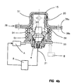
- Figures 4a and 4b show a device according to a third embodiment of the invention.
- the holes 20 carried by the internal bowl 15 are closed by a mobile screen constituted by a sheath cylindrical 51 which can translate with respect to the internal bowl 15 and following the direction materialized by axis 21 of initiator 4.
- the screen 51 has a base 52 on which is fixed initiator 4 which therefore moves with the screen.
- the fixing is ensured as described previously by a crimping 14 of a shim 12 with interposition of a seal O-ring seal 13.
- the device according to this embodiment comprises a external bowl 53 in pressed sheet metal which is made integral of the internal bowl 15 (for example by welding) at the level of their circular collars 38a, 38b.
- the collars 38a, 38b are applied to each other and form a crown 38 for fixing the device on the system 3 by means of screws 7.
- the two internal 15 and external 53 cuvettes define thus a cavity inside which can translate screen 51.
- a compression spring 54 is disposed around the external bowl 53 and between a collar 55 integral with the base 52 and a flat bearing surface formed by the collar 38b of the external bowl 53.
- the spring 54 is in the compressed position when the device is in its safety position (figure 4b).
- the spring 54 acts as an actuator means allowing the transition from the safety position to the armed position.
- the actuator means is released by a means of unlocking which is here constituted by a lock electromagnetic A which is operated by the electronic unit 8 for vehicle safety.
- any other type of means of unlocking could be adopted including a way to pyrotechnic unlocking.
- the bowl external 53 carries holes 56 regularly distributed angularly (here four holes) made according to radial directions and substantially in the vicinity of the flange 38b.
- sheath 51 carries four holes 57 each having an axis inclined to the axis 21 of the initiator and scabbard.
- the holes 57 are opposite holes 56 arranged on the external bowl 53.
- the screen 51 will be linked in rotation to the external bowl 53 by a means not shown (for example a pawn linked to the bowl and circulating in a longitudinal groove of screen).
- a means not shown for example a pawn linked to the bowl and circulating in a longitudinal groove of screen.
- Lock A is connected to electronic vehicle control means. He is free automatically a few milliseconds before triggering from the initiator 4.
- an actuator B may be provided (shown in dotted lines), for example electromagnetic, which can act at will on the flange 55 of the device to cause the sheath 51 to move from one position to the other. Such a provision will make the reversible device. The system will then normally be in safety position and actuator B will control the passage in armed position a few seconds after starting the vehicle or when the speed exceeds a threshold.
- Figures 5a and 5b show another mode of achievement which differs from the previous one in that the spring of compression 54 is placed inside the bowl external and around the base 52.
- the device is shown attached to the system 3 at the Figure 5a and disassembled in Figure 5b.
- the spring 54 is thus compressed between a shoulder 58 of the base 52 and the external bowl 53 when the device is in its armed position ( Figure 5a) and at least partially relaxed when the device is in its safety position ( Figure 5b).
- This device also differs from the previous one in that it includes a washer 59 which covers the base 52 and which is made integral by a connecting means (here a crimping annular 60).
- the washer 59 carries two fingers 61a, 61b which extend substantially parallel to the base 52.
- the fingers pass through the flanges 38a, 38b by holes 62, 63 and they thus extend along the bowl internal 15.
- the fingers 61a and 61b form with the spring 54 the actuator means of the device.
- any disassembly of the fixing screws 7 of the device will automatically cause the device to return to a safety position in which the holes 20 are closed and the flames generated by the initiator cannot reach the gas generator 5.
- FIGS 6a and 6b show another mode of close realization in its operation of the following one Figures 4a and 4b.
- This mode differs from the mode according to FIGS. 4a / 4b in that that the spring 54 is disposed inside the sheath 51 of the screen. The spring is thus supported between the bowl internal 15 and the base 52.
- the spring 54 is in the compressed state when the device is in its safety position (figure 6b) and it is at least partially relaxed when the device found in the armed position ( Figure 6a).
- This mode also differs from the mode of FIGS. 4a / 4b by the structure of the means for unlocking the spring.
- this means comprises a pyrotechnic component 65 which is connected to the electronic means 8 for controlling the vehicle safety.
- Component 65 is disposed in a housing 66 which is fixed, for example by welding, on the external surface of the external bowl 53.
- the component is made integral axially of the housing by an elastic retaining washer 67 which rests on the internal cylindrical surface of a housing housing.
- Component 65 is placed in a cylindrical cell thin 68 forming a rod which penetrates inside the external bowl 53 through a hole 69 and which plays the stop role supported by a notch semi-cylindrical 70 produced on the base 52.
- the alveolus 68 is made of stamped sheet metal and it receives component 65. This cell is pierced axially. So the gases generated by component 65 can be exercised through this drilling on the base 52.
- the component will thus be a gas generating component which will retreat under the effect of the shock and pressure it generates, driving the rod / cell 68 and adopting a position (as shown in Figure 6a) in which it will be released from notch 70.
- the pyrotechnic component 65 could also be a pyrotechnic retractor comprising a rod 68 which would disappear during the initiation of the component.
- Figures 7a and 7b show another mode of realization of a device according to the invention.
- This mode differs from all previous modes in that it consists of a single initiator component which is intended (with some dimensional adaptations) to be mounted inside a conventional security system.
- This component includes a closed metal case 71, the interior of which is arranged a first composition pyrotechnic 72 which is intended to ensure the initiation of a gas generator (not shown) through holes radial 97 (here four holes).
- the first part of component 1 forms an initiator pyrotechnics of classical structure. It includes a bucket 73 metallic inside which is placed the first pyrotechnic composition 72 which will be for example a redox composition possibly associated with a primary explosive.
- Bucket 73 is closed by a glass / metal base 74 comprising two metal electrodes 75a, 75b (electrodes main).
- the electrode 75a is welded in a hole in the body 77 of the metal base 74, the electrode 75b passes through the latter and it is electrically isolated by a insulator 76 (glass).
- the metal body 77 of the base 64 is drilled to receive the insulator 76 and the electrode 75b.
- a resistive initiating element such as a wire 78 or a plate of semiconductor is attached to the outside of the body 77 and connects electrically the electrodes 75a, 75b
- the body 77 is fixed to the bucket 73 for example by welding laser and the first pyrotechnic composition 72 is found in contact with the resistive element 78.
- the bucket 73 is insulated electrically from the case 71 by an insulating ring 79, by plastic example.
- a screen means is here constituted by a tube 80 slidably mounted in the case 71 and which plugs the holes in the safety position ( Figure 7a) radial 97.
- the tube 80 is kept applied by a first spring compression 81 against a locking means which is consisting of a split cylindrical sleeve 82, one of which end abuts against a first internal counterbore 83 of case 71.
- the sleeve 82 is made for example of steel with spring. It is split and surrounds a first litter cylindrical 84 of a locking rod 85.
- the rod 85 has a second cylindrical seat 86 of diameter smaller than that of the first.
- the bearing diameters 84.86 and the geometry of the socket 82 are chosen so that socket 82 is finds constraint in the open state when it is on the range 84 and that it closes by its elasticity for adopt the diameter of the second span 86 when you moves rod 85.
- the rod 85 comprises a conductive core 87 which is surrounded by an insulating body 88 on which the worn 84.86.
- Rod 85 is pushed into its locked position of the sleeve by a second compression spring 89 (metallic) which rests on one side on the bucket 73 and the other on the insulating body 88.
- the spring 89 surrounds a rear extension 90 of the core 87.
- the spring adjustment 89 on this rear extension is slightly tight. So, he there is electrical continuity between bucket 73 and the core 87 via spring 89.
- a front part of the rod 85 carries a cup cylindrical metallic 92 which is electrically isolated from core 87 and which is in electrical contact with the body of case 71.
- This cup 92 constitutes a first electrode, called safety, while the core 87 constitutes a second safety electrode.
- a resistive element 93 such as a wire or a semiconductor wafer is disposed between these two safety electrodes.
- a second pyrotechnic composition 94 covers this resistive element 93.
- case 71 is closed at its rear part by a metallic plug 95 welded to the body of the case 71, by example by laser.
- An insulating washer 96 is interposed between the plug 95 and the body 77 and the cup 73.
- the axial positioning relative to the case 71 of the main initiator formed by the body 77 carrying the bucket 73 is provided by the support of a fold 98 of the ring insulating 79 on an internal countersink 99 of the case.
- the initiator according to the invention therefore comprises two pyrotechnic compositions 72 and 94 which can be initiated, the first (72) by a current flowing between the main electrodes 75a, 75b, the second (94) by a current flowing between the safety electrodes 92 and 87, i.e. between electrode 75a (which is connected to electrode 87 via bucket 73 and spring 89) and the case 71 itself which is connected to the electrode 92.
- the tube 80 plugs the holes 97.
- the gases generated by the composition cannot leave the component and remain confined to inside the case 71 whose thickness and material will be chosen so as to ensure such confinement. We could for example make a case of 0.5 mm steel.
- Such a component therefore makes it possible to avoid losses of vehicle control that would result from an initiation untimely security device outside of everything accident background.
- a firing order will be sent to the second composition pyrotechnic 94 a few milliseconds before sending the first firing order.
- the gases generated by the initiation of the second composition 94 have the effect of pushing the rod 85 into rear against the action of the spring 89.
- the sleeve 82 being also blocked axially by the spring 81, such retraction of the rod 85 has the effect of positioning the second cylindrical seat 86 opposite the elastic sleeve 82. Such positioning has the effect of releasing the socket 82 which resiliently adopts the diameter of the second span 86 and thus frees the screen tube 80.
- the spring then pushes the tube 80 up to the stop against the first counterbore 83 which releases the holes 97.
- the component is then in his armed position shown in the Figure 7b.
- the holes 97 are cleared and the initiation of the first composition 72 will trigger the system protection pyrotechnics.
Landscapes
- Physics & Mathematics (AREA)
- Fluid Mechanics (AREA)
- Engineering & Computer Science (AREA)
- Mechanical Engineering (AREA)
- Air Bags (AREA)
- Lock And Its Accessories (AREA)
Applications Claiming Priority (2)
| Application Number | Priority Date | Filing Date | Title |
|---|---|---|---|
| FR9916327A FR2802873B1 (fr) | 1999-12-23 | 1999-12-23 | Dispositif de securite pyrotechnique pour vehicule |
| FR9916327 | 1999-12-23 |
Publications (2)
| Publication Number | Publication Date |
|---|---|
| EP1110826A1 true EP1110826A1 (de) | 2001-06-27 |
| EP1110826B1 EP1110826B1 (de) | 2004-03-10 |
Family
ID=9553699
Family Applications (1)
| Application Number | Title | Priority Date | Filing Date |
|---|---|---|---|
| EP00403534A Expired - Lifetime EP1110826B1 (de) | 1999-12-23 | 2000-12-15 | Pyrotechnische Sicherheitsvorrichtung für ein Kraftfahrzeug |
Country Status (5)
| Country | Link |
|---|---|
| EP (1) | EP1110826B1 (de) |
| AT (1) | ATE261364T1 (de) |
| DE (1) | DE60008844T2 (de) |
| ES (1) | ES2215014T3 (de) |
| FR (1) | FR2802873B1 (de) |
Cited By (3)
| Publication number | Priority date | Publication date | Assignee | Title |
|---|---|---|---|---|
| US6543801B2 (en) * | 1999-09-24 | 2003-04-08 | Livbag Snc | Inflatable metal structure with built-in pyrotechnic charge |
| EP1346886A1 (de) * | 2000-12-27 | 2003-09-24 | Daicel Chemical Industries, Ltd. | Gasgenerator zur verwendung bei airbags und airbagvorrichtung |
| FR2865173A1 (fr) * | 2004-01-20 | 2005-07-22 | Trw Airbag Sys Gmbh | Dispositif d'actionnement d'un systeme de securite de vehicule |
Families Citing this family (1)
| Publication number | Priority date | Publication date | Assignee | Title |
|---|---|---|---|---|
| DE102006002435A1 (de) * | 2006-01-12 | 2007-07-26 | Takata-Petri Ag | Verfahren zur Herstellung eines Gasgenerators und mittels des Verfahrens hergestellter Gasgenerator |
Citations (4)
| Publication number | Priority date | Publication date | Assignee | Title |
|---|---|---|---|---|
| FR2691706A1 (fr) * | 1992-06-02 | 1993-12-03 | Livbag Snc | Générateur pyrotechnique de gaz muni d'une ouverture de sécurité. |
| US5602361A (en) * | 1994-03-18 | 1997-02-11 | Oea, Inc. | Hybrid inflator |
| DE19702259C1 (de) * | 1997-01-23 | 1998-02-05 | Temic Bayern Chem Airbag Gmbh | Gasgenerator |
| US5970880A (en) * | 1997-03-14 | 1999-10-26 | Livbag S.N.C. | Pyrotechnic gas generator with adaptable flow rate and volume for air bags |
-
1999
- 1999-12-23 FR FR9916327A patent/FR2802873B1/fr not_active Expired - Fee Related
-
2000
- 2000-12-15 AT AT00403534T patent/ATE261364T1/de not_active IP Right Cessation
- 2000-12-15 EP EP00403534A patent/EP1110826B1/de not_active Expired - Lifetime
- 2000-12-15 ES ES00403534T patent/ES2215014T3/es not_active Expired - Lifetime
- 2000-12-15 DE DE60008844T patent/DE60008844T2/de not_active Expired - Fee Related
Patent Citations (4)
| Publication number | Priority date | Publication date | Assignee | Title |
|---|---|---|---|---|
| FR2691706A1 (fr) * | 1992-06-02 | 1993-12-03 | Livbag Snc | Générateur pyrotechnique de gaz muni d'une ouverture de sécurité. |
| US5602361A (en) * | 1994-03-18 | 1997-02-11 | Oea, Inc. | Hybrid inflator |
| DE19702259C1 (de) * | 1997-01-23 | 1998-02-05 | Temic Bayern Chem Airbag Gmbh | Gasgenerator |
| US5970880A (en) * | 1997-03-14 | 1999-10-26 | Livbag S.N.C. | Pyrotechnic gas generator with adaptable flow rate and volume for air bags |
Cited By (5)
| Publication number | Priority date | Publication date | Assignee | Title |
|---|---|---|---|---|
| US6543801B2 (en) * | 1999-09-24 | 2003-04-08 | Livbag Snc | Inflatable metal structure with built-in pyrotechnic charge |
| EP1346886A1 (de) * | 2000-12-27 | 2003-09-24 | Daicel Chemical Industries, Ltd. | Gasgenerator zur verwendung bei airbags und airbagvorrichtung |
| EP1346886A4 (de) * | 2000-12-27 | 2005-03-30 | Daicel Chem | Gasgenerator zur verwendung bei airbags und airbagvorrichtung |
| US7114746B2 (en) | 2000-12-27 | 2006-10-03 | Daicel Chemical Industries, Ltd. | Air bag-use gas generator and air bag device |
| FR2865173A1 (fr) * | 2004-01-20 | 2005-07-22 | Trw Airbag Sys Gmbh | Dispositif d'actionnement d'un systeme de securite de vehicule |
Also Published As
| Publication number | Publication date |
|---|---|
| EP1110826B1 (de) | 2004-03-10 |
| FR2802873B1 (fr) | 2002-03-22 |
| ES2215014T3 (es) | 2004-10-01 |
| DE60008844T2 (de) | 2005-01-05 |
| DE60008844D1 (de) | 2004-04-15 |
| ATE261364T1 (de) | 2004-03-15 |
| FR2802873A1 (fr) | 2001-06-29 |
Similar Documents
| Publication | Publication Date | Title |
|---|---|---|
| EP0879739B1 (de) | Adaptativer, pyrotechnischer Gasgenerator mit rohrförmigen Kammern für einen Airbag | |
| EP3711077B1 (de) | Pyrotechnische schaltvorrichtung | |
| EP2195542B1 (de) | Aktuator mit hubaktivierung, insbesondere für ein automobilsicherheitssystem zum schutz von fussgängern | |
| EP1137559A1 (de) | Mit hilfe eines kolbens pyrotechnisch entriegelbare mechanische verbindungsvorrichtung | |
| EP1172261A1 (de) | Entlüftungsvorrichtung eines aufblasbaren Elements und Aufprallschutzeinrichtung für ein Fahrzeug mit einer derartigen Vorrichtung | |
| WO2020099474A1 (fr) | Dispositif de securite pour circuit-electrique de vehicule | |
| EP2271848B1 (de) | Stellzylinder zum anheben einer motorhaube, mit deaktivierbarer bremsvorrichtung für die rückbewegung. | |
| FR2999129A1 (fr) | Ensemble actionneur pyrotechnique et module de coussin de securite gonflable equipe de celui-ci | |
| EP1110826B1 (de) | Pyrotechnische Sicherheitsvorrichtung für ein Kraftfahrzeug | |
| EP0901946B1 (de) | Anpassungsfähiger, pyrotechnischer Gasgenerator für ein Luftkissen, mit Neutralisierungseinrichtung | |
| EP1495918A2 (de) | Stossabsorbierende Vorrichtung eines Fahrzeugteils mit einem Metallfaden | |
| EP1304268A1 (de) | Hybrid-Gasgenerator für einen Airbag | |
| EP1080001A1 (de) | Steuervorrichtung eines kraftfahrzeugorgans mit hilfe von einem pedal | |
| WO2004076962A1 (fr) | Fusee de projectile | |
| FR2589618A1 (fr) | Dispositif de protection pour condensateur en boitier etanche | |
| WO2001001026A1 (fr) | Soupape de surpression | |
| EP0427593B1 (de) | Zigarrenanzünder, insbesondere für ein Kraftfahrzeug | |
| EP1557341A1 (de) | Vorrichtung zum Festhalten einer Fahrzeugmotorhaube | |
| FR3071658B1 (fr) | Dispositif pyrotechnique destine a ouvrir un premier circuit electrique et a fermer un deuxieme circuit electrique | |
| FR2888548A1 (fr) | Dispositif de diffusion de gaz destine a la securite automobile | |
| FR2689833A1 (fr) | Dispositif électrique de veille capable de déclencher un appareil de sécurité sur un véhicule, notamment automobile, et appareil de sécurité équipé d'un tel dispositif. | |
| CH693116A5 (fr) | Fusée de projectile. | |
| EP0534840A1 (de) | Druckempfindliche pyrotechnische Einrichtung wie zum Beispiel Signalsprengbüchse, Mine oder dergleichen | |
| FR2865451A1 (fr) | Systeme de retenue du capot d'un vehicule automobile | |
| WO1988009047A1 (fr) | Serrure a barillet, notamment pour automobile |
Legal Events
| Date | Code | Title | Description |
|---|---|---|---|
| PUAI | Public reference made under article 153(3) epc to a published international application that has entered the european phase |
Free format text: ORIGINAL CODE: 0009012 |
|
| AK | Designated contracting states |
Kind code of ref document: A1 Designated state(s): AT BE CH CY DE DK ES FI FR GB GR IE IT LI LU MC NL PT SE TR |
|
| AX | Request for extension of the european patent |
Free format text: AL;LT;LV;MK;RO;SI |
|
| 17P | Request for examination filed |
Effective date: 20010926 |
|
| AKX | Designation fees paid |
Free format text: AT BE CH CY DE DK ES FI FR GB GR IE IT LI LU MC NL PT SE TR |
|
| GRAH | Despatch of communication of intention to grant a patent |
Free format text: ORIGINAL CODE: EPIDOS IGRA |
|
| GRAH | Despatch of communication of intention to grant a patent |
Free format text: ORIGINAL CODE: EPIDOS IGRA |
|
| GRAH | Despatch of communication of intention to grant a patent |
Free format text: ORIGINAL CODE: EPIDOS IGRA |
|
| REG | Reference to a national code |
Ref country code: GB Ref legal event code: FG4D Free format text: NOT ENGLISH |
|
| GRAH | Despatch of communication of intention to grant a patent |
Free format text: ORIGINAL CODE: EPIDOS IGRA |
|
| GRAA | (expected) grant |
Free format text: ORIGINAL CODE: 0009210 |
|
| AK | Designated contracting states |
Kind code of ref document: B1 Designated state(s): AT BE CH CY DE DK ES FI FR GB GR IE IT LI LU MC NL PT SE TR |
|
| PG25 | Lapsed in a contracting state [announced via postgrant information from national office to epo] |
Ref country code: TR Free format text: LAPSE BECAUSE OF FAILURE TO SUBMIT A TRANSLATION OF THE DESCRIPTION OR TO PAY THE FEE WITHIN THE PRESCRIBED TIME-LIMIT Effective date: 20040310 Ref country code: NL Free format text: LAPSE BECAUSE OF FAILURE TO SUBMIT A TRANSLATION OF THE DESCRIPTION OR TO PAY THE FEE WITHIN THE PRESCRIBED TIME-LIMIT Effective date: 20040310 Ref country code: IE Free format text: LAPSE BECAUSE OF FAILURE TO SUBMIT A TRANSLATION OF THE DESCRIPTION OR TO PAY THE FEE WITHIN THE PRESCRIBED TIME-LIMIT Effective date: 20040310 Ref country code: FI Free format text: LAPSE BECAUSE OF FAILURE TO SUBMIT A TRANSLATION OF THE DESCRIPTION OR TO PAY THE FEE WITHIN THE PRESCRIBED TIME-LIMIT Effective date: 20040310 Ref country code: CY Free format text: LAPSE BECAUSE OF FAILURE TO SUBMIT A TRANSLATION OF THE DESCRIPTION OR TO PAY THE FEE WITHIN THE PRESCRIBED TIME-LIMIT Effective date: 20040310 Ref country code: AT Free format text: LAPSE BECAUSE OF FAILURE TO SUBMIT A TRANSLATION OF THE DESCRIPTION OR TO PAY THE FEE WITHIN THE PRESCRIBED TIME-LIMIT Effective date: 20040310 |
|
| REG | Reference to a national code |
Ref country code: CH Ref legal event code: EP |
|
| GBT | Gb: translation of ep patent filed (gb section 77(6)(a)/1977) |
Effective date: 20040310 |
|
| REG | Reference to a national code |
Ref country code: IE Ref legal event code: FG4D Free format text: FRENCH |
|
| REF | Corresponds to: |
Ref document number: 60008844 Country of ref document: DE Date of ref document: 20040415 Kind code of ref document: P |
|
| PG25 | Lapsed in a contracting state [announced via postgrant information from national office to epo] |
Ref country code: GR Free format text: LAPSE BECAUSE OF FAILURE TO SUBMIT A TRANSLATION OF THE DESCRIPTION OR TO PAY THE FEE WITHIN THE PRESCRIBED TIME-LIMIT Effective date: 20040610 Ref country code: DK Free format text: LAPSE BECAUSE OF FAILURE TO SUBMIT A TRANSLATION OF THE DESCRIPTION OR TO PAY THE FEE WITHIN THE PRESCRIBED TIME-LIMIT Effective date: 20040610 |
|
| NLV1 | Nl: lapsed or annulled due to failure to fulfill the requirements of art. 29p and 29m of the patents act | ||
| REG | Reference to a national code |
Ref country code: ES Ref legal event code: FG2A Ref document number: 2215014 Country of ref document: ES Kind code of ref document: T3 |
|
| REG | Reference to a national code |
Ref country code: IE Ref legal event code: FD4D |
|
| PGFP | Annual fee paid to national office [announced via postgrant information from national office to epo] |
Ref country code: SE Payment date: 20041125 Year of fee payment: 5 Ref country code: DE Payment date: 20041125 Year of fee payment: 5 |
|
| PGFP | Annual fee paid to national office [announced via postgrant information from national office to epo] |
Ref country code: GB Payment date: 20041130 Year of fee payment: 5 |
|
| PGFP | Annual fee paid to national office [announced via postgrant information from national office to epo] |
Ref country code: ES Payment date: 20041207 Year of fee payment: 5 |
|
| PG25 | Lapsed in a contracting state [announced via postgrant information from national office to epo] |
Ref country code: LU Free format text: LAPSE BECAUSE OF NON-PAYMENT OF DUE FEES Effective date: 20041215 |
|
| PG25 | Lapsed in a contracting state [announced via postgrant information from national office to epo] |
Ref country code: MC Free format text: LAPSE BECAUSE OF NON-PAYMENT OF DUE FEES Effective date: 20041231 Ref country code: LI Free format text: LAPSE BECAUSE OF NON-PAYMENT OF DUE FEES Effective date: 20041231 Ref country code: CH Free format text: LAPSE BECAUSE OF NON-PAYMENT OF DUE FEES Effective date: 20041231 Ref country code: BE Free format text: LAPSE BECAUSE OF NON-PAYMENT OF DUE FEES Effective date: 20041231 |
|
| PLBE | No opposition filed within time limit |
Free format text: ORIGINAL CODE: 0009261 |
|
| STAA | Information on the status of an ep patent application or granted ep patent |
Free format text: STATUS: NO OPPOSITION FILED WITHIN TIME LIMIT |
|
| 26N | No opposition filed |
Effective date: 20041213 |
|
| BERE | Be: lapsed |
Owner name: *GIAT INDUSTRIES Effective date: 20041231 |
|
| REG | Reference to a national code |
Ref country code: CH Ref legal event code: PL |
|
| PG25 | Lapsed in a contracting state [announced via postgrant information from national office to epo] |
Ref country code: FR Free format text: LAPSE BECAUSE OF NON-PAYMENT OF DUE FEES Effective date: 20050831 |
|
| REG | Reference to a national code |
Ref country code: FR Ref legal event code: ST |
|
| PG25 | Lapsed in a contracting state [announced via postgrant information from national office to epo] |
Ref country code: IT Free format text: LAPSE BECAUSE OF NON-PAYMENT OF DUE FEES;WARNING: LAPSES OF ITALIAN PATENTS WITH EFFECTIVE DATE BEFORE 2007 MAY HAVE OCCURRED AT ANY TIME BEFORE 2007. THE CORRECT EFFECTIVE DATE MAY BE DIFFERENT FROM THE ONE RECORDED. Effective date: 20051215 Ref country code: GB Free format text: LAPSE BECAUSE OF NON-PAYMENT OF DUE FEES Effective date: 20051215 |
|
| PG25 | Lapsed in a contracting state [announced via postgrant information from national office to epo] |
Ref country code: SE Free format text: LAPSE BECAUSE OF NON-PAYMENT OF DUE FEES Effective date: 20051216 Ref country code: ES Free format text: LAPSE BECAUSE OF NON-PAYMENT OF DUE FEES Effective date: 20051216 |
|
| PG25 | Lapsed in a contracting state [announced via postgrant information from national office to epo] |
Ref country code: DE Free format text: LAPSE BECAUSE OF NON-PAYMENT OF DUE FEES Effective date: 20060701 |
|
| EUG | Se: european patent has lapsed | ||
| GBPC | Gb: european patent ceased through non-payment of renewal fee |
Effective date: 20051215 |
|
| REG | Reference to a national code |
Ref country code: ES Ref legal event code: FD2A Effective date: 20051216 |
|
| BERE | Be: lapsed |
Owner name: *GIAT INDUSTRIES Effective date: 20041231 |
|
| PG25 | Lapsed in a contracting state [announced via postgrant information from national office to epo] |
Ref country code: PT Free format text: LAPSE BECAUSE OF NON-PAYMENT OF DUE FEES Effective date: 20040810 |