EP1110693A2 - Apparatus and method for preparing a calendered elastomeric sheet - Google Patents
Apparatus and method for preparing a calendered elastomeric sheet Download PDFInfo
- Publication number
- EP1110693A2 EP1110693A2 EP00127058A EP00127058A EP1110693A2 EP 1110693 A2 EP1110693 A2 EP 1110693A2 EP 00127058 A EP00127058 A EP 00127058A EP 00127058 A EP00127058 A EP 00127058A EP 1110693 A2 EP1110693 A2 EP 1110693A2
- Authority
- EP
- European Patent Office
- Prior art keywords
- calender
- reinforcement
- slip ring
- roll
- rolls
- Prior art date
- Legal status (The legal status is an assumption and is not a legal conclusion. Google has not performed a legal analysis and makes no representation as to the accuracy of the status listed.)
- Granted
Links
Images


Classifications
-
- B—PERFORMING OPERATIONS; TRANSPORTING
- B29—WORKING OF PLASTICS; WORKING OF SUBSTANCES IN A PLASTIC STATE IN GENERAL
- B29C—SHAPING OR JOINING OF PLASTICS; SHAPING OF MATERIAL IN A PLASTIC STATE, NOT OTHERWISE PROVIDED FOR; AFTER-TREATMENT OF THE SHAPED PRODUCTS, e.g. REPAIRING
- B29C43/00—Compression moulding, i.e. applying external pressure to flow the moulding material; Apparatus therefor
- B29C43/22—Compression moulding, i.e. applying external pressure to flow the moulding material; Apparatus therefor of articles of indefinite length
- B29C43/24—Calendering
-
- B—PERFORMING OPERATIONS; TRANSPORTING
- B29—WORKING OF PLASTICS; WORKING OF SUBSTANCES IN A PLASTIC STATE IN GENERAL
- B29C—SHAPING OR JOINING OF PLASTICS; SHAPING OF MATERIAL IN A PLASTIC STATE, NOT OTHERWISE PROVIDED FOR; AFTER-TREATMENT OF THE SHAPED PRODUCTS, e.g. REPAIRING
- B29C59/00—Surface shaping of articles, e.g. embossing; Apparatus therefor
- B29C59/16—Surface shaping of articles, e.g. embossing; Apparatus therefor by wave energy or particle radiation, e.g. infrared heating
-
- Y—GENERAL TAGGING OF NEW TECHNOLOGICAL DEVELOPMENTS; GENERAL TAGGING OF CROSS-SECTIONAL TECHNOLOGIES SPANNING OVER SEVERAL SECTIONS OF THE IPC; TECHNICAL SUBJECTS COVERED BY FORMER USPC CROSS-REFERENCE ART COLLECTIONS [XRACs] AND DIGESTS
- Y10—TECHNICAL SUBJECTS COVERED BY FORMER USPC
- Y10S—TECHNICAL SUBJECTS COVERED BY FORMER USPC CROSS-REFERENCE ART COLLECTIONS [XRACs] AND DIGESTS
- Y10S29/00—Metal working
- Y10S29/032—Rolling with other step
-
- Y—GENERAL TAGGING OF NEW TECHNOLOGICAL DEVELOPMENTS; GENERAL TAGGING OF CROSS-SECTIONAL TECHNOLOGIES SPANNING OVER SEVERAL SECTIONS OF THE IPC; TECHNICAL SUBJECTS COVERED BY FORMER USPC CROSS-REFERENCE ART COLLECTIONS [XRACs] AND DIGESTS
- Y10—TECHNICAL SUBJECTS COVERED BY FORMER USPC
- Y10T—TECHNICAL SUBJECTS COVERED BY FORMER US CLASSIFICATION
- Y10T29/00—Metal working
- Y10T29/49—Method of mechanical manufacture
- Y10T29/4998—Combined manufacture including applying or shaping of fluent material
- Y10T29/49982—Coating
-
- Y—GENERAL TAGGING OF NEW TECHNOLOGICAL DEVELOPMENTS; GENERAL TAGGING OF CROSS-SECTIONAL TECHNOLOGIES SPANNING OVER SEVERAL SECTIONS OF THE IPC; TECHNICAL SUBJECTS COVERED BY FORMER USPC CROSS-REFERENCE ART COLLECTIONS [XRACs] AND DIGESTS
- Y10—TECHNICAL SUBJECTS COVERED BY FORMER USPC
- Y10T—TECHNICAL SUBJECTS COVERED BY FORMER US CLASSIFICATION
- Y10T29/00—Metal working
- Y10T29/53—Means to assemble or disassemble
- Y10T29/53126—Means to place sheath on running-length core
-
- Y—GENERAL TAGGING OF NEW TECHNOLOGICAL DEVELOPMENTS; GENERAL TAGGING OF CROSS-SECTIONAL TECHNOLOGIES SPANNING OVER SEVERAL SECTIONS OF THE IPC; TECHNICAL SUBJECTS COVERED BY FORMER USPC CROSS-REFERENCE ART COLLECTIONS [XRACs] AND DIGESTS
- Y10—TECHNICAL SUBJECTS COVERED BY FORMER USPC
- Y10T—TECHNICAL SUBJECTS COVERED BY FORMER US CLASSIFICATION
- Y10T29/00—Metal working
- Y10T29/53—Means to assemble or disassemble
- Y10T29/53526—Running-length work
- Y10T29/5353—Assembled on core
Definitions
- the invention relates to apparatus and a method of processing elastomeric materials.
- the process is directed to a means of producing carbon carbon bonds in a vulcanizable elastomer, and in particular, an elastomer that contains wire reinforcement.
- Electron beam processing is known in the art for treating elastomeric materials to enhance their green strength.
- EBP activates carbon atoms in a polymer and induces carbon carbon crosslinking.
- Carbon carbon cross linking in a green elastomer gives the elastomer added strength that makes it possible in some cases, and easier in other cases, to handle the green elastomer during processing before vulcanization.
- Electron beam processing is known to induce an electromotive force in wire cords, along with a potentially high voltage, and for such reasons electron beam processing of wire reinforced elastomers has been generally avoided in the past.
- a method of forming a reinforced composite 17 on a calender 11 comprises the steps of a) grounding guide rolls 19 that contact reinforcement 12 from a creel 18 prior to feeding the reinforcement 12 to a calender 11, b) coating the reinforcement 12 with rubber 23 while on the calender 11 to form a reinforced composite 17, and c) grounding rolls which contact the reinforced composite as the composite exits the calender 11.
- the method in steps (a) and (c) may further comprise the steps of I) attaching slip rings 36 to rolls 14,15,19,21 which contact the reinforcement 12 and the composite 17 on the calender 11, and II) connecting the slip rings 36 to ground 27.
- the method in step (a), comprising grounding reinforcement 12 from a creel 18, may further comprise the further steps of I) drilling and tapping the end of a roller shaft 32a to provide a threaded hole 37 for receipt of a bolt 39, II) threading a first end of bolt 39 into the threaded hole 37, III) attaching a slip ring 36 to a second end of the bolt 39, whereby the slip ring 36 rotates with the roll 32, IV) connecting a second bolt 38 to bearings within the slip ring 36 and attaching an electrical terminal 34 to the second bolt 38 whereby the terminal 34 remains stationary, and V) connecting the terminal 34 to ground 27.
- the method may comprise the further step of subjecting the reinforced composite to electron beam processing (EBP).
- EBP electron beam processing
- the method may include the further step of placing at least one roll above the plane of the reinforced composite and at least one roll below the plane of the reinforced composite. Also, a further step of connecting bare wires to ground during calender changeover may be used.
- the method includes the step of subjecting a calendered sheet comprising rubber-coated wire to an electron beam of 2 to 14 mega-RADs.
- the slip ring 36 is provided as a mercury wetted slip ring.
- an apparatus 10 for grounding materials on a calender 11 which is used to coat wire reinforcement 12 with rubber 23, wherein the apparatus 10 comprises, a) at least one roll 14,15,19,21 for transporting material through a calender, b) at least one slip ring 36 connected to the roll whereby the slip ring 36 rotates with the roll while a terminal 34 attached to the slip ring stays substantially stationary while the roll rotates, and c) an electrical conductor 26 connecting each of the at least one slip ring 36 to ground 27.
- the apparatus 10 may further comprise d) an organizer roll 15 for directing wire through the calender 11, the roll having a first end of a conductive rod attached at one end thereof, and e) a slip ring 36 attached to a second end of the conductive rod 39.
- At least one roll is an organizer roll 15, and the conductive rod is a bolt 39 having a first end threaded into a threaded hole 37 in an end of the organizer roll. Also, a terminal 34 is connected to bolt 38 which is connected to bearings in slip ring 36.
- the calender 11 includes apparatus 16 for applying a rubber coat on material passing through the calender 11.
- the apparatus 10 may include at least one grounding point on the calendered sheet 17 downstream of the calender 11, the at least one grounding point optimally comprising a guide roll 21 for the calendered sheet.
- the apparatus further comprises an electron beam source 28 associated with the calender 11 down stream of a rubber coating apparatus 16 on the calender 11.
- Fig. 1 illustrates the apparatus of the invention, which comprises a calender, a rubber application unit, and an electron beam processor.
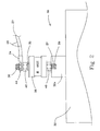
- Fig. 2 illustrates the means of grounding potential in the apparatus in one embodiment of the invention.
- Fig. 3 illustrates a perspective view of organizer rolls, which is part of the embodiment of Fig. 1.
- the apparatus 10 of the invention comprises a calender 11, a rubber application means 16, and an electron beam-processing unit 28.
- a creel 18 may be used to store cord or filament material that is fed into the calender, and a festoon 20 may be used to collect the calendered sheet of composite material.
- wires 12 are fed to the calender 11 from a creel 18, and are directed to the calender via organizer rolls 15, and coated with rubber 23 at the calender via impression rolls 14, which are part of rubber application means 16.
- rubber 23 is applied to the reinforcement 12 by the action of the calender rolls 14 and continues through the calender line until it is collected upon exiting on festoon 20.
- the apparatus 10 of the invention includes an electron beam processing unit 28 downstream of the rubber application means 16, which is used to bombard the newly created, green calender material with an electron beam to induce carbon carbon linkage within the polymers of the calendered sheet 17.
- the processed calendered material 17 is collected in a roll on a windup (not shown).
- At least one of impression rolls 14, and at least one of organizer rolls 15 are connected to ground 27 using electrical conductors 26 (Fig. 2).
- impression rolls 14, festoon rolls 21, guide rolls 19, and organizer rolls 15, and optionally cooling drums 45 are efficient grounding contacts since they cover the full width of the calendered sheet 17, and the entire surface of the calendered sheet passes over or under the rolls.
- grounding system developed for the present apparatus was intended to reduce the induced potential created by electron beam processing, it has been found that the grounding system also effectively eliminates static buildup on calendered sheets that do not contain wire reinforcement.
- connection to ground is obtained by attaching a slip ring 36 to the end of each of the roll where a ground connection is made, wherein the bearings in slip ring 36 permit the slip ring 36 to rotate with a roll 32 while isolator 35 permits terminal 34 to remain stationary.
- the slip ring 36 may be attached to a roll 19, 15, 14, 21 by any convenient mechanical means, for example a rod welded to the end of a roll shaft 32a.
- wire 12 passes over roll 32, which has a drilled and tapped hole 37 in one end thereof.
- roll 32 represents generically any of the rolls associated with the calender which may be connected to ground.
- a bolt 39 is threaded into drilled and tapped hole 37 and held tightly in place by nut 40.
- Slip ring 36 is carried on bolt 39, and rotates as roll 32 rotates.
- Bolt 38 is connected to bearings (not shown) in slip ring 36, whereby the rotation of slip ring 36 is isolated from bolt 38. Therefore, bolt 38 remains stationary while slip ring 36 and roll 32 rotate.
- terminal 34 is held on bolt 38 by nuts 42 and 44. Terminal 34 is connected to electrical conductors 26, which are connected to the factory ground 27.
- Terminal 34 fits over bolt 38, and when attached to bolt 38 may make electrical contact with the slip ring assembly directly through bolt 38, or indirectly through nuts 42 and 44.
- a reinforced composite 17 is formed on a calender 11 comprising the steps of a) grounding guide rolls 15,19 which are used to feed the reinforcement 12 to a calender 11, b) coating the reinforcement 12 with rubber 23 while on the calender 11 to form a reinforced composite 17, and c) grounding rolls 21, 45 which contact the reinforced composite 17 after the composite exits the calender 11.
- the method further comprises attaching slip rings 36 to rolls 14 that contact the reinforcement 12 and the composite 17 on the calender 11, and connecting the slip ring 36 to ground 27.
- step a) may further comprise grounding reinforcement 12 by 1) drilling and tapping the end of a roller 32 or shaft 32a to provide a threaded hole 37 for receipt of a bolt 39, 2) threading a first end of a bolt 39 into the threaded hole 27, 3) attaching a slip ring 36 to a second end of the bolt 39, and 4) connecting the slip ring 36 to ground 27.
- the method further comprises the step of subjecting the reinforced composite 17 to electron beam processing.
- At least one roll is provided above the plane of the reinforced composite, and at least one roll is provided below the plane of the reinforced composite.
- the electron beam may comprise a beam of 2 to 14 mega-RADs.
- slip rings 36 are mercury wetted slip rings.
- the method and apparatus of the invention are used to treat a wire-reinforced product with electron beam processing (EBP).
- EBP electron beam processing
- the calender was modified to provide nine ground points throughout the line. Four grounding points were established on roll, which contact the wire reinforcement before the wire reaches the calender. Five additional grounding points were established downstream on the calender, and after the calender, as an added safety factor, and to reduce static buildup on the calendered sheet and to ground the bare cords during calender changeover.
- the test was repeated by doubling the output of the electron beam processor, and the same results were achieved.
Landscapes
- Engineering & Computer Science (AREA)
- Mechanical Engineering (AREA)
- Casting Or Compression Moulding Of Plastics Or The Like (AREA)
- Synthetic Leather, Interior Materials Or Flexible Sheet Materials (AREA)
- Reinforced Plastic Materials (AREA)
- Heating, Cooling, Or Curing Plastics Or The Like In General (AREA)
Abstract
Description
Claims (6)
- A method of forming a reinforced composite on a calender (11) comprising the steps of:(a) grounding rolls (15,19) contacting reinforcement (12) from a creel (18) prior to feeding the reinforcement (12) to a calender (11);(b) coating said reinforcement (12) with rubber (23) while on the calender (11) to form a reinforced composite (17); and(c) grounding rolls (21,45) contacting the reinforced composite (17) after the composite exits the calender.
- The method of claim 1 wherein steps (a) and (c) further comprise the steps of(I) attaching slip rings (36) to rolls (15,19,14,21,45) which contact the reinforcement (12) and the composite (17) on the calender; and(II) connecting the slip rings (36) to ground (27).
- The method of claim 1 comprising the further step of subjecting said reinforced composite (17) to electron beam processing (EBP).
- An apparatus for grounding materials on a calender (11) which is used to coat wire reinforcement (12) with rubber (23), the apparatus comprising
(a) at least one roll (19,15,14) for transporting material through a calender (11),
characterized in that(b) at least one slip ring (36) is connected to said roll whereby said slip ring (36) stays substantially stationary while said roll rotates, and in that(c) an electrical conductor (26) connects said at least one slip ring (36) to ground (27). - The apparatus of claim 4 further characterized by at least one grounding point on said calendered sheet (17) downstream of said calender (11), said at least one grounding point comprising a guide roller (21) for said calendered sheet (17).
- The apparatus of claim 5 further characterized by an electron beam source (28) associated with said calender (11) downstream of a rubber coating apparatus (16) on said calender (11).
Applications Claiming Priority (2)
| Application Number | Priority Date | Filing Date | Title |
|---|---|---|---|
| US467691 | 1983-02-18 | ||
| US09/467,691 US6425970B1 (en) | 1999-12-21 | 1999-12-21 | Method for grounding EBP processing |
Publications (3)
| Publication Number | Publication Date |
|---|---|
| EP1110693A2 true EP1110693A2 (en) | 2001-06-27 |
| EP1110693A3 EP1110693A3 (en) | 2002-05-29 |
| EP1110693B1 EP1110693B1 (en) | 2003-10-08 |
Family
ID=23856729
Family Applications (1)
| Application Number | Title | Priority Date | Filing Date |
|---|---|---|---|
| EP00127058A Expired - Lifetime EP1110693B1 (en) | 1999-12-21 | 2000-12-11 | Apparatus and method for preparing a calendered elastomeric sheet |
Country Status (7)
| Country | Link |
|---|---|
| US (1) | US6425970B1 (en) |
| EP (1) | EP1110693B1 (en) |
| JP (1) | JP4723721B2 (en) |
| BR (1) | BR0005834A (en) |
| CA (1) | CA2320630A1 (en) |
| DE (1) | DE60005774T2 (en) |
| ES (1) | ES2207457T3 (en) |
Cited By (1)
| Publication number | Priority date | Publication date | Assignee | Title |
|---|---|---|---|---|
| DE10327679A1 (en) * | 2003-06-20 | 2005-01-05 | Continental Aktiengesellschaft | Calendering plant with multi-roll calender for application of rubber compound onto both sides of textile or steel cords is fed by cold feed extruders with roller heads |
Families Citing this family (1)
| Publication number | Priority date | Publication date | Assignee | Title |
|---|---|---|---|---|
| US20080204869A1 (en) * | 2007-02-27 | 2008-08-28 | Stewart Grant W | Counter top projection screen and counter structure |
Family Cites Families (11)
| Publication number | Priority date | Publication date | Assignee | Title |
|---|---|---|---|---|
| GB1469180A (en) * | 1974-08-17 | 1977-03-30 | Singer Co | Tufting machine having a yarn feed roller assembly |
| US5000807A (en) * | 1987-03-03 | 1991-03-19 | Concordia Mfg. Co., Inc. | Apparatus and method for commingling continuous multifilament yarns |
| JPH0334805A (en) * | 1989-06-30 | 1991-02-14 | Tonen Corp | Removing mechanism for static electricity in prepreg producing equipment |
| JPH0464708A (en) * | 1990-07-02 | 1992-02-28 | Ishikawajima Harima Heavy Ind Co Ltd | Roll supporting structure |
| US5190774A (en) * | 1991-02-01 | 1993-03-02 | Bridgestone/Firestone Inc. | Apparatus for calendering cords with elastomeric material |
| US5169450A (en) * | 1991-04-18 | 1992-12-08 | American Roller Company | Corona treatment roller electrode |
| JPH05208458A (en) * | 1992-01-31 | 1993-08-20 | Toyo Tire & Rubber Co Ltd | Manufacture of topping sheet for structure material of tire |
| JPH05208457A (en) * | 1992-01-31 | 1993-08-20 | Toyo Tire & Rubber Co Ltd | Topping sheet for tire component and method for manufacturing the same |
| JPH05245851A (en) * | 1992-03-05 | 1993-09-24 | Yokohama Rubber Co Ltd:The | Manufacture of constituent member of tire |
| JPH0817590A (en) * | 1994-06-28 | 1996-01-19 | Achilles Corp | Antistatic roll |
| US6295931B1 (en) * | 1998-03-11 | 2001-10-02 | Tpl, Inc. | Integrated magnetic field sensors for fuzes |
-
1999
- 1999-12-21 US US09/467,691 patent/US6425970B1/en not_active Expired - Fee Related
-
2000
- 2000-09-25 CA CA002320630A patent/CA2320630A1/en not_active Abandoned
- 2000-12-11 EP EP00127058A patent/EP1110693B1/en not_active Expired - Lifetime
- 2000-12-11 DE DE60005774T patent/DE60005774T2/en not_active Expired - Fee Related
- 2000-12-11 ES ES00127058T patent/ES2207457T3/en not_active Expired - Lifetime
- 2000-12-12 BR BR0005834-3A patent/BR0005834A/en active Search and Examination
- 2000-12-21 JP JP2000388446A patent/JP4723721B2/en not_active Expired - Fee Related
Cited By (1)
| Publication number | Priority date | Publication date | Assignee | Title |
|---|---|---|---|---|
| DE10327679A1 (en) * | 2003-06-20 | 2005-01-05 | Continental Aktiengesellschaft | Calendering plant with multi-roll calender for application of rubber compound onto both sides of textile or steel cords is fed by cold feed extruders with roller heads |
Also Published As
| Publication number | Publication date |
|---|---|
| EP1110693A3 (en) | 2002-05-29 |
| US6425970B1 (en) | 2002-07-30 |
| DE60005774T2 (en) | 2004-07-29 |
| BR0005834A (en) | 2001-07-24 |
| EP1110693B1 (en) | 2003-10-08 |
| DE60005774D1 (en) | 2003-11-13 |
| JP4723721B2 (en) | 2011-07-13 |
| ES2207457T3 (en) | 2004-06-01 |
| JP2001212839A (en) | 2001-08-07 |
| CA2320630A1 (en) | 2001-06-21 |
Similar Documents
| Publication | Publication Date | Title |
|---|---|---|
| EP0002453A1 (en) | Device for the surface treatment of strips of foil by electrical corona discharge | |
| US4108701A (en) | Method for making hose incorporating an embedded static ground conductor | |
| EP0490838B1 (en) | Method and apparatus to check the acceptability of the state of wear in the covering fabric of a driving belt | |
| EP0844067A3 (en) | Method and apparatus for centering belt-shaped material | |
| US6471799B1 (en) | Method and device for producing gypsum boards | |
| EP1110693B1 (en) | Apparatus and method for preparing a calendered elastomeric sheet | |
| EP0671255A1 (en) | Process and apparatus for the automatic depositing and splicing of webs on a tyre building drum | |
| DE2642007B2 (en) | Method and device for reducing the lateral force fluctuations exerted on the roadway by a loaded pneumatic tire | |
| DE19716325C2 (en) | Device for electrostatically charging a multi-layer strand | |
| SE512917C2 (en) | Method, apparatus and cable guide for winding an electric machine | |
| US4168198A (en) | Apparatus for making hose incorporating an embedded static ground conductor | |
| MXPA00012290A (en) | Apparatus and method for preparing a calendered elastomeric sheet | |
| EP1775369B1 (en) | Laundry dryer and method for detecting the drum rotation | |
| FI74226C (en) | FOERFARANDE FOER ELEKTRISK MOTSTAONDS-RULLSVETSNING OCH SVETSMASKIN FOER GENOMFOERANDE AV FOERFARANDET. | |
| EP0971851A1 (en) | Method and device for electrostatic charging | |
| US4412960A (en) | Method for processing a strip of polymer material by electrical discharge | |
| US4091855A (en) | Process for improving the ammonolytic stability of polyester textile yarn | |
| ATE255186T1 (en) | METHOD AND DEVICE FOR PRODUCING A METAL ROPE FOR REINFORCING ELASTOMER PRODUCTS, IN PARTICULAR Pneumatic TIRES | |
| US4717870A (en) | Slasher moisture monitoring system | |
| US3444289A (en) | Method and heat-treating machine for material in strip form | |
| US2754883A (en) | Apparatus for tension-calendering fabric | |
| CN209177658U (en) | A kind of flexure equipment | |
| US7108247B2 (en) | Method and apparatus for lifting and/or conveying | |
| CH630843A5 (en) | Printing apparatus with electrically assisted transfer of the printing ink | |
| FI79144B (en) | ARRANGEMANG FOER KATODISKT SKYDDANDE AV EN SUGVALS I EN PAPPERSMASKIN. |
Legal Events
| Date | Code | Title | Description |
|---|---|---|---|
| PUAI | Public reference made under article 153(3) epc to a published international application that has entered the european phase |
Free format text: ORIGINAL CODE: 0009012 |
|
| AK | Designated contracting states |
Kind code of ref document: A2 Designated state(s): AT BE CH CY DE DK ES FI FR GB GR IE IT LI LU MC NL PT SE TR |
|
| AX | Request for extension of the european patent |
Free format text: AL;LT;LV;MK;RO;SI |
|
| PUAL | Search report despatched |
Free format text: ORIGINAL CODE: 0009013 |
|
| AK | Designated contracting states |
Kind code of ref document: A3 Designated state(s): AT BE CH CY DE DK ES FI FR GB GR IE IT LI LU MC NL PT SE TR |
|
| AX | Request for extension of the european patent |
Free format text: AL;LT;LV;MK;RO;SI |
|
| 17P | Request for examination filed |
Effective date: 20021129 |
|
| AKX | Designation fees paid |
Designated state(s): DE ES FR GB IT |
|
| GRAH | Despatch of communication of intention to grant a patent |
Free format text: ORIGINAL CODE: EPIDOS IGRA |
|
| GRAS | Grant fee paid |
Free format text: ORIGINAL CODE: EPIDOSNIGR3 |
|
| GRAA | (expected) grant |
Free format text: ORIGINAL CODE: 0009210 |
|
| AK | Designated contracting states |
Kind code of ref document: B1 Designated state(s): DE ES FR GB IT |
|
| REG | Reference to a national code |
Ref country code: GB Ref legal event code: FG4D |
|
| REG | Reference to a national code |
Ref country code: IE Ref legal event code: FG4D |
|
| REF | Corresponds to: |
Ref document number: 60005774 Country of ref document: DE Date of ref document: 20031113 Kind code of ref document: P |
|
| ET | Fr: translation filed | ||
| REG | Reference to a national code |
Ref country code: ES Ref legal event code: FG2A Ref document number: 2207457 Country of ref document: ES Kind code of ref document: T3 |
|
| PLBE | No opposition filed within time limit |
Free format text: ORIGINAL CODE: 0009261 |
|
| STAA | Information on the status of an ep patent application or granted ep patent |
Free format text: STATUS: NO OPPOSITION FILED WITHIN TIME LIMIT |
|
| REG | Reference to a national code |
Ref country code: IE Ref legal event code: MM4A |
|
| 26N | No opposition filed |
Effective date: 20040709 |
|
| PGFP | Annual fee paid to national office [announced via postgrant information from national office to epo] |
Ref country code: GB Payment date: 20061106 Year of fee payment: 7 |
|
| PGFP | Annual fee paid to national office [announced via postgrant information from national office to epo] |
Ref country code: FR Payment date: 20061201 Year of fee payment: 7 |
|
| PGFP | Annual fee paid to national office [announced via postgrant information from national office to epo] |
Ref country code: ES Payment date: 20061222 Year of fee payment: 7 |
|
| PGFP | Annual fee paid to national office [announced via postgrant information from national office to epo] |
Ref country code: DE Payment date: 20061229 Year of fee payment: 7 |
|
| PGFP | Annual fee paid to national office [announced via postgrant information from national office to epo] |
Ref country code: IT Payment date: 20071217 Year of fee payment: 8 |
|
| GBPC | Gb: european patent ceased through non-payment of renewal fee |
Effective date: 20071211 |
|
| PG25 | Lapsed in a contracting state [announced via postgrant information from national office to epo] |
Ref country code: DE Free format text: LAPSE BECAUSE OF NON-PAYMENT OF DUE FEES Effective date: 20080701 |
|
| REG | Reference to a national code |
Ref country code: FR Ref legal event code: ST Effective date: 20081020 |
|
| PG25 | Lapsed in a contracting state [announced via postgrant information from national office to epo] |
Ref country code: GB Free format text: LAPSE BECAUSE OF NON-PAYMENT OF DUE FEES Effective date: 20071211 |
|
| REG | Reference to a national code |
Ref country code: ES Ref legal event code: FD2A Effective date: 20071212 |
|
| PG25 | Lapsed in a contracting state [announced via postgrant information from national office to epo] |
Ref country code: ES Free format text: LAPSE BECAUSE OF NON-PAYMENT OF DUE FEES Effective date: 20071212 Ref country code: FR Free format text: LAPSE BECAUSE OF NON-PAYMENT OF DUE FEES Effective date: 20071231 |
|
| PG25 | Lapsed in a contracting state [announced via postgrant information from national office to epo] |
Ref country code: IT Free format text: LAPSE BECAUSE OF NON-PAYMENT OF DUE FEES Effective date: 20081211 |