EP1110637A2 - Method for producing a component and component - Google Patents
Method for producing a component and component Download PDFInfo
- Publication number
- EP1110637A2 EP1110637A2 EP00127774A EP00127774A EP1110637A2 EP 1110637 A2 EP1110637 A2 EP 1110637A2 EP 00127774 A EP00127774 A EP 00127774A EP 00127774 A EP00127774 A EP 00127774A EP 1110637 A2 EP1110637 A2 EP 1110637A2
- Authority
- EP
- European Patent Office
- Prior art keywords
- metal
- cross
- metal tubes
- section
- tubular
- Prior art date
- Legal status (The legal status is an assumption and is not a legal conclusion. Google has not performed a legal analysis and makes no representation as to the accuracy of the status listed.)
- Granted
Links
Images
Classifications
-
- B—PERFORMING OPERATIONS; TRANSPORTING
- B21—MECHANICAL METAL-WORKING WITHOUT ESSENTIALLY REMOVING MATERIAL; PUNCHING METAL
- B21D—WORKING OR PROCESSING OF SHEET METAL OR METAL TUBES, RODS OR PROFILES WITHOUT ESSENTIALLY REMOVING MATERIAL; PUNCHING METAL
- B21D26/00—Shaping without cutting otherwise than using rigid devices or tools or yieldable or resilient pads, i.e. applying fluid pressure or magnetic forces
- B21D26/02—Shaping without cutting otherwise than using rigid devices or tools or yieldable or resilient pads, i.e. applying fluid pressure or magnetic forces by applying fluid pressure
- B21D26/053—Shaping without cutting otherwise than using rigid devices or tools or yieldable or resilient pads, i.e. applying fluid pressure or magnetic forces by applying fluid pressure characterised by the material of the blanks
- B21D26/057—Tailored blanks
-
- B—PERFORMING OPERATIONS; TRANSPORTING
- B21—MECHANICAL METAL-WORKING WITHOUT ESSENTIALLY REMOVING MATERIAL; PUNCHING METAL
- B21C—MANUFACTURE OF METAL SHEETS, WIRE, RODS, TUBES OR PROFILES, OTHERWISE THAN BY ROLLING; AUXILIARY OPERATIONS USED IN CONNECTION WITH METAL-WORKING WITHOUT ESSENTIALLY REMOVING MATERIAL
- B21C37/00—Manufacture of metal sheets, bars, wire, tubes or like semi-manufactured products, not otherwise provided for; Manufacture of tubes of special shape
- B21C37/06—Manufacture of metal sheets, bars, wire, tubes or like semi-manufactured products, not otherwise provided for; Manufacture of tubes of special shape of tubes or metal hoses; Combined procedures for making tubes, e.g. for making multi-wall tubes
-
- B—PERFORMING OPERATIONS; TRANSPORTING
- B21—MECHANICAL METAL-WORKING WITHOUT ESSENTIALLY REMOVING MATERIAL; PUNCHING METAL
- B21D—WORKING OR PROCESSING OF SHEET METAL OR METAL TUBES, RODS OR PROFILES WITHOUT ESSENTIALLY REMOVING MATERIAL; PUNCHING METAL
- B21D35/00—Combined processes according to or processes combined with methods covered by groups B21D1/00 - B21D31/00
- B21D35/002—Processes combined with methods covered by groups B21D1/00 - B21D31/00
- B21D35/005—Processes combined with methods covered by groups B21D1/00 - B21D31/00 characterized by the material of the blank or the workpiece
- B21D35/006—Blanks having varying thickness, e.g. tailored blanks
Definitions
- the invention relates to a method for producing a tubular molded component and on such a molded component.
- the diameters of conventionally manufactured inexpensive pipes especially continuously in roll forming manufactured pipes, tolerances, for example a wall thickness of one or more millimeters a few tenths Can be millimeters. So with simple face welding of the pipes, in particular pipes with thin walls, possibly bad or incomplete Connection of the pipe ends or an undesirable step formation achieved become. For this purpose, the end areas of the Pipes are checked and measured; however, this requires again an additional step.
- the invention has for its object improvements over to create the prior art and in particular a method for producing a molded component and a corresponding molded component to create a safe with relatively little effort and preferably inexpensive manufacture of molded components various pipes, especially molded parts with stronger ones Allow variation along the axial length.
- This task is solved on the one hand by a method for manufacturing a molded component in which at least one metal tube of at least two metal pipes of different cross-sections and / or different wall thickness and / or different Material properties of the cross section of at least one End area is changed so that end faces the end regions of the two metal tubes matched to one another and the cross sections of the end regions of the metal pipes are the corresponding ones Cross sections of the molded component or one of the hydroforming process used outer shape at least essentially correspond.
- the metal pipes are on the front End faces subsequently together to form a tubular semi-finished product welded, the following in a hydroforming process is deformed.
- this task is carried out in the molded component mentioned at the beginning solved by connecting the two tubular sections
- the weld seam is at least largely stress-free.
- This Molded component is in particular by the method according to the invention producible.
- a tubular end region or tubular End areas of both metal tubes in their cross section of an end shape of the molded component must at least largely correspond to the area the weld seam in the subsequent hydroforming process just widened a little so that the metal in the area of the weld, advantageously only in one Dimensions are expanded so that it remains in its flowable area and thus no or only low tensions in the Area of the weld.
- the cross section of the end region of a metal pipe or the cross sections of the end regions of both metal pipes thus changed so that the end faces of the End areas are adapted to each other, so that a good connection the pipe ends can be guaranteed during the welding process.
- the end faces of metal pipes different wall thicknesses can e.g. flush with the scope be adjusted so that there is a smooth outer surface of the tubular Semi-finished product and later the molded component, so that the different wall thicknesses of the pipe materials from the outside are recognizable.
- the cross sections of the end regions of the Metal pipes of the corresponding cross section of the final shape that is the cross section of the molded component or the area of the outer shape, the the end areas of the pipes or the connecting area of the Surrounds semi-finished product when inserted into the outer shape, at least largely adjusted or adjusted.
- a uniform gap between the connection area of the semi-finished product and the inner surface of the outer mold remain; however, it is also the formation of an uneven gap possible, so that subsequent IHU deformations a greater deformation of a part of the connection area is reached.
- the gap between that Connection area and the inner surface of the outer shape can for example a few millimeters or a few tenths of a millimeter.
- the gap is advantageously chosen such that the metal during the subsequent hydroforming only experiences a relative stretch at which it is still in its is flowable area, so in the area of the weld no or only low voltages are generated.
- the end regions of the metal tubes can in particular be mechanical be deformed.
- an expanding mandrel can be used, for example a taper by means of a narrowing ring and / or an end pulling device can be achieved.
- the changed cross section of the metal pipe is independent of the tolerances of the original workpieces and is only determined by these tools.
- Both metal tubes have a bonded deformation that is independent on the wall thickness or the material properties of the pipes can.
- this can advantageously be used to change the cross section of the end area used tool in the following Welding process remain on the metal pipe so that through the tool a good fixation of the end area of the tube is achieved, without resilience of the metal after the change in cross-section again a change in shape of the end area occurs.
- the welding device can in particular already during or before the step of changing the cross-section, i.e. in particular the expansion process or the narrowing process to which Pipe ends are created.
- a common tool e.g. one common narrowing ring in which the pipe ends from both sides be inserted or by a common expanding mandrel the two pipe ends are pushed on from two sides.
- the common expanding mandrel as a retractable expanding mandrel is formed, it can be retracted after welding or folded and axially from the tubular semi-finished product be removed.
- the common tool can be used in the subsequent Welding process basically also in the welding process be included, e.g. serve as an electrode for welding; if the tool is not used in the welding process it can advantageously be grounded.
- Pipes in cross section can be changed if the cross section a tube already essentially the final shape of the molded component corresponds.
- the cross section of the end region can of the pipe can be changed with a smaller wall thickness.
- the Tolerances in the pipe with a larger wall thickness are particularly then not significant if the pipe has a thinner wall inside of the tolerance range with its entire face End face on the front end face of the tube with a larger Wall thickness is present.
- an in Circumferential groove may be formed for receiving the weld between the pipe ends serves.
- This will, on the one hand post-processing of the semi-finished product in the area of Switzerland seam and on the other hand a strain on the outer shape the solidified, generally wedge-shaped weld in the hydraulic Expansion process avoided or at least kept low, so that the life of the outer shape is increased.
- the groove can also be axial Fixing the semi-finished product during the hydroforming process be used.
- An outer mold or a die or a device for hydroforming, in the inside surface of the outer shape such a circumferential groove for receiving a weld seam is already in itself Unique position viewed as an essential concept of the invention.
- the groove can be so deep in relation to the weld seam be designed so that the weld seam even during expansion does not rest on the groove base and only the pipe end areas lie next to the weld seam on the outer shape; in this Fall is only by the axial forces at the weld Expanding burdened.
- the groove can be made smaller Depth are formed so that the weld seam during of widening rests on the base of the groove and, if necessary, is slightly deformed becomes.
- the pipe ends to a Post-treatment of the weld seam can be dispensed with if the outer shape is formed with the groove running in the circumferential direction, because in this case damage to the tool and the load the weld seam and the load on the surrounding weld seam Metal is avoided during expansion or at least is low.
- Electrodes can be used to weld the end faces or a friction welding process can be used.
- the end faces are controlled by means of a magnet Arc welding process welded together.
- the axial tracking of the pipe material can advantageously one in the connection area of the end areas of Metal pipes of different wall thickness, beveled step or be equalized, whereby the strength of the Connection is increased and a smoother connection surface is created becomes.
- the pipe material can only be axial Direction (for example from the side of the pipe with less Wall thickness and / or smaller diameter or the tube with larger wall thickness and / or larger diameter) or both axial directions are tracked.
- the tracking from the both axial directions can be the same or advantageous different ways, for example at different speeds and / or staggered and / or over a shorter one or longer distance. Both when tracking out an axial direction as well as from both axial directions when using an outer shape with a groove on its inner surface Fixation of the weld seam of the semi-finished product reached in the axial direction become; however, it is also a corresponding axial tracking possible without such a fixation.
- steel pipes in particular can be used; however, it is also the use of other metals, in particular Light metals, such as magnesium, aluminum or a magnesium or aluminum alloy possible.
- Light metals such as magnesium, aluminum or a magnesium or aluminum alloy possible.
- metal pipes with different material properties be connected, e.g. different types of steel, e.g. Steel grades with different composition or different Structure.
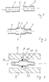
- a first metal tube 1 and a second metal tube 2 used e.g. a circular cross section, a have a rectangular cross section or another cross section.
- the metal tubes 1, 2 have different, as shown in FIG. 1 Wall thicknesses and / or different diameters.
- end regions 3, 4 of the metal tubes are expanded in such a way that that end faces 5, 6 of the end regions 3, 4 are matched to one another and subsequently the metal tubes 1, 2 can be placed against each other at their end faces 5, 6, so that advantageously at least one end face, e.g. as in Fig. 2 shown the smaller end face 5, completely on the other Face 6 rests.
- the end regions 3, 4 have already been expanded in such a way that their cross sections the cross section of the final shape, that is, the later Molded component at this point, at least largely correspond, or their outer diameter the inner diameter of the in used later IHU expansion process, shown in Fig. 3 9 correspond at least largely.
- the pipe ends 3, 4 can be on Fig. 2 following welding process e.g. through a pressure welding process, especially a magnetically controlled arc welding process are welded together.
- a pressure welding process especially a magnetically controlled arc welding process are welded together.
- an electrode welding process can also be used be used, where appropriate, to expand the Pipe ends 3, 4 used expanding mandrel, not shown in Fig. 2 can be used as one of the electrodes.
- connection area 13 which has the end regions 3, 4 as the starting material used metal pipes 1, 2 corresponds.
- a weld 7 which is formed as in Fig. 3 shown can protrude in particular to the outside.
- the semifinished product 8 in a manner known per se inserted into an outer shape 9, which is the final shape of the later tubular Determined component. To expand this is known in Way fluid, as shown by arrow F, inside the Semi-finished product 8 pressed, generally the other end of the Semi-finished product 8 is closed.
- connection area 13 already during the previous expansion area of the outer shape 9 surrounding it is at least largely adapted is and advantageously only a small, ring-shaped Gap 11 between the connection area 13 and the outer shape 9 remains, this connection area in the hydroforming process only slightly stretched, so that in particular also the load on the end region 3 of the metal pipe with less Wall thickness near the weld 7 kept low is so that there is no or only a small amount in the weld seam Voltages are generated.
- the diameter of the metal pipe and the gap is coordinated so that the Elongation of the metal in the radial direction within the flow area of the metal takes place.
- An annular groove 10 can be formed in the outer shape 9, which is suitable for receiving the weld seam 7.
- the weld seam 7 thus enters the groove, so that a flat pressing of the weld 7 on a smooth inner surface the outer shape 9 can be avoided.
- the groove 10 can are so deep that the weld 7 is not at all or only partially comes to rest on the groove base, so that the Load on the weld 7 is low. Alternatively, you can a deliberate deformation of the weld when using a groove can be achieved with a smaller depth, so that the Weld 7 is somewhat flattened.
- the axial length of the end regions changed in their cross section 3, 4 can in the mechanical expansion according to the invention before Welding of the two metal tubes is different his.
- the axial length of the end region 3 of the metal tube 1 with smaller wall thickness larger or smaller chosen as the axial length of the end region 4 of the metal tube 2 are, depending on the desired load on the pipe material at mechanical expansion as well as in the subsequent hydroforming.
- one or both end areas can also be narrowed.
- a first tube with a smaller diameter and one second pipe with a larger diameter can, for example End region of the first tube expanded and the end region of the second tube are narrowed, so that the end regions against each other are adjusted.
- a narrowing of both end areas can, for example be made when the connection area in the later Molded component has a smaller diameter than the surrounding areas of the molded component and for example below the molded component in the relatively flexible connection area should be bent.
- sheet metal can be produced continuously roll-formed or discontinuously roll-rolled or die-bent, relatively inexpensive pipes are used. This can then pulling and annealing the pipes if necessary to be dispensed with because the subsequent widening of the pipe ends according to the invention also larger tolerances of the output pipes can be accepted. This can also weaken the material by pulling and Glow pipes are avoided.
- tubes 1, 2 can be of constant or non-uniform Wall thickness can be used.
- An uneven wall thickness can be done, for example, by pretreatment for pipe manufacturing used sheets can be achieved.
Landscapes
- Engineering & Computer Science (AREA)
- Mechanical Engineering (AREA)
- Physics & Mathematics (AREA)
- Fluid Mechanics (AREA)
- Shaping Metal By Deep-Drawing, Or The Like (AREA)
- Transition And Organic Metals Composition Catalysts For Addition Polymerization (AREA)
- Processing And Handling Of Plastics And Other Materials For Molding In General (AREA)
- Heating, Cooling, Or Curing Plastics Or The Like In General (AREA)
- Pressure Welding/Diffusion-Bonding (AREA)
Abstract
Description
Die Erfindung bezieht sich auf ein Verfahren zum Herstellen eines rohrförmigen Formbauteils und auf ein derartiges Formbauteil.The invention relates to a method for producing a tubular molded component and on such a molded component.
Die EP 0 620 056 B1 beschreibt bereits ein derartiges Verfahren sowie ein derartiges Formbauteil. Hierbei werden Rohre unterschiedlichen Querschnittes, unterschiedlicher Wandstärke und unterschiedlicher Materialeigenschaften in einem ersten Arbeitsschritt stirnseitig zu einem Halbzeug verschweißt. Dieses rohrförmige Halbzeug kann anschließend in einem Innenhochdruck-Umformverfahren zu einem rohrförmigen Formbauteil aufgeweitet werden. Durch die Verwendung des aus verschiedenen Rohren zusammengesetzen Halbzeuges können Formbauteile mit stärkeren Variationen der Wanddicke und stärkeren Variationen der Querschnittsfläche hergestellt werden, als es bei Verwendung eines einfachen Rohres als Halbzeug möglich ist, bei dem in Bereichen größerer radialer Aufweitung eine stärkere Verdünnung der Wandstärke bewirkt wird. Indem das rohrförmige Halbzeug durch Verschweißen herkömmlicher, kostengünstiger Rohre erzeugt wird, kann es relativ kostengünstig hergestellt werden und dennoch für die Herstellung unterschiedlicher Formbauteile mit größeren Variationen entlang seiner axialen Länge verwendet werden. EP 0 620 056 B1 already describes such a method and such a molded component. Here pipes are different Cross-section, different wall thickness and different Material properties in a first step welded to a semi-finished product on the face. This tubular Semi-finished products can then be produced using a hydroforming process be expanded to a tubular molded component. By using the composed of different pipes Semi-finished products can be molded components with greater variations the wall thickness and greater variations in the cross-sectional area be made than it is when using a simple Pipe is possible as a semi-finished product, with larger areas radial expansion causes a greater thinning of the wall thickness becomes. By welding the tubular semi-finished product conventional, inexpensive pipes is produced, it can be relative can be produced inexpensively and yet for the production different molded components with larger variations can be used along its axial length.
Bei diesem Herstellungsverfahren können jedoch im Verbindungsbereich der beiden Metallrohre, insbesondere wenn Metallrohre unterschiedlicher Wandstärken und unterschiedlichen Ausdehnungsverhaltens verwendet werden, Probleme auftreten. So kann bei dem Innenhochdruck-Umformverfahren das Rohr mit der geringeren Wandstärke zuerst aufgeweitet werden, so daß es in seinem Endbereich, d.h. im Verbindungsbereich des Halbzeuges bei der Schweißnaht, stärker gestreckt und ausgedünnt wird. Hierbei können bei stärkerer Ausdünnung gegebenenfalls auch Risse in der Schweißnaht, in einer Wärmeeinflußzone neben der Schweißnaht und / oder in einem Grundwerkstoff außerhalb der Wärmeeinflußzone des Metallrohres auftreten. Weiterhin kann es beim nachfolgenden Aufweiten des Rohres mit größerer Wandstärke in dem zuvor stärker gestreckten Endbereich des Rohres mit geringerer Wandstärke zu einer unerwünschten Faltenbildung kommen.In this manufacturing process, however, in the connection area of the two metal pipes, especially if metal pipes are different Wall thicknesses and different expansion behavior problems are encountered. So can with the hydroforming process the pipe with the smaller wall thickness be expanded first so that it is in its end region, i.e. in the Connection area of the semi-finished product at the weld, stronger is stretched and thinned. In this case, with greater thinning if necessary, cracks in the weld seam, in one Heat affected zone next to the weld seam and / or in a base material occur outside the heat affected zone of the metal pipe. It can also be used for the subsequent expansion of the tube greater wall thickness in the previously stretched end area of the tube with less wall thickness to an undesirable wrinkling come.
Desweiteren haben die Durchmesser von konventionell hergestellten, kostengünstigen Rohren, insbesondere kontinuierlich im Rollformverfahren hergestellten Rohre, Toleranzen, die zum Beispiel bei einer Wandstärke von einem oder mehreren Millimetern einige Zehntel Millimeter betragen können. Somit kann beim einfachen stirnseitigen Verschweißen der Rohre, insbesondere von Rohren mit geringer Wandstärke, eventuell eine schlechte oder unvollständige Verbindung der Rohrenden bzw. eine unerwünschte Stufenbildung erreicht werden. Hierzu können zwar zunächst die Endbereiche der Rohre überprüft und vermessen werden; dies erfordert jedoch wiederum einen zusätzlichen Arbeitsschritt.Furthermore, the diameters of conventionally manufactured inexpensive pipes, especially continuously in roll forming manufactured pipes, tolerances, for example a wall thickness of one or more millimeters a few tenths Can be millimeters. So with simple face welding of the pipes, in particular pipes with thin walls, possibly bad or incomplete Connection of the pipe ends or an undesirable step formation achieved become. For this purpose, the end areas of the Pipes are checked and measured; however, this requires again an additional step.
Durch die relativ feste Schweißnaht zwischen den Rohrenden kann weiterhin beim Innenhochdruck-Umformverfahren auf Dauer die Innenfläche der Außenform beschädigt werden, insbesondere wenn die Schweißnaht im Verbindungsbereich keilförmig nach außen ragt.Due to the relatively tight weld between the pipe ends in the case of the internal high-pressure forming process, the inner surface in the long term the outer shape, especially if the The weld seam in the connection area protrudes outwards in a wedge shape.
Der Erfindung liegt die Aufgabe zugrunde, Verbesserungen gegenüber dem Stand der Technik zu schaffen und insbesondere ein Verfahren zum Herstellen eines Formbauteils sowie ein entsprechendes Formbauteil zu schaffen, die mit relativ geringem Aufwand eine sichere und vorzugsweise kostengünstige Herstellung von Formbauteilen aus verschiedenen Rohren, insbesondere auch Formbauteilen mit stärkerer Variation entlang der axialen Länge ermöglichen.The invention has for its object improvements over to create the prior art and in particular a method for producing a molded component and a corresponding molded component to create a safe with relatively little effort and preferably inexpensive manufacture of molded components various pipes, especially molded parts with stronger ones Allow variation along the axial length.
Diese Aufgabe wird zum einen gelöst durch ein Verfahren zum Herstellen eines Formbauteils, bei dem bei mindestens einem Metallrohr von mindestens zwei Metallrohren unterschiedlichen Querschnittes und/oder unterschiedlicher Wandstärke und/oder unterschiedlicher Materialeigenschaften der Querschnitt mindestens eines Endbereiches derartig verändert wird, daß stirnseitige Endflächen der Endbereiche der beiden Metallrohre an einander angepaßt sind und die Querschnitte der Endbereiche der Metallrohre den entsprechenden Querschnitten des Formbauteils bzw. einer beim Innenhochdruck-Umformverfahren benutzten Außenform zumindest im wesentlichen entsprechen. Die Metallrohre werden an den stirnseitigen Endflächen nachfolgend miteinander zu einem rohrförmigen Halbzeug verschweißt, das nachfolgend in einem Innenhochdruck-Umformverfahren verformt wird.This task is solved on the one hand by a method for manufacturing a molded component in which at least one metal tube of at least two metal pipes of different cross-sections and / or different wall thickness and / or different Material properties of the cross section of at least one End area is changed so that end faces the end regions of the two metal tubes matched to one another and the cross sections of the end regions of the metal pipes are the corresponding ones Cross sections of the molded component or one of the hydroforming process used outer shape at least essentially correspond. The metal pipes are on the front End faces subsequently together to form a tubular semi-finished product welded, the following in a hydroforming process is deformed.
Weiterhin wird diese Aufgabe bei dem eingangs genannten Formbauteil gelöst, indem die die beiden rohrförmigen Abschnitte verbindende Schweißnaht zumindest weitgehend spannungsfrei ist. Dieses Formbauteil ist insbesondere nach dem erfindungsgemäßen Verfahren herstellbar. Indem ein rohrförmiger Endbereich bzw. rohrförmige Endbereiche beider Metallrohre in ihrem Querschnitt einer Endform des Formbauteils zumindest weitgehend entsprechen, muss der Bereich der Schweißnaht beim nachfolgenden Innenhochdruck-Umformverfahren lediglich ein wenig aufgeweitet werden, so dass das Metall im Bereich der Schweißnaht vorteilhafterweise lediglich in einem Maße aufgeweitet wird, dass es in seinem fließfähigem Bereich verbleibt und somit keine bzw. lediglich geringe Spannungen in den Bereich der Schweißnaht erzeugt werden.Furthermore, this task is carried out in the molded component mentioned at the beginning solved by connecting the two tubular sections The weld seam is at least largely stress-free. This Molded component is in particular by the method according to the invention producible. By a tubular end region or tubular End areas of both metal tubes in their cross section of an end shape of the molded component must at least largely correspond to the area the weld seam in the subsequent hydroforming process just widened a little so that the metal in the area of the weld, advantageously only in one Dimensions are expanded so that it remains in its flowable area and thus no or only low tensions in the Area of the weld.
Erfindungsgemäß werden der Querschnitt des Endbereiches eines Metallrohres oder die Querschnitte der Endbereiche beider Metallrohre somit derartig verändert, daß die stirnseitigen Endflächen der Endbereiche aneinander angepaßt sind, so daß eine gute Verbindung der Rohrenden beim Schweißverfahren gewährleistet werden kann. Somit können nicht nur präzise, gezogene Rohre bzw. gezogene und geglühte Rohre, sondern beispielsweise kostengünstige, kontinuierlich rollgeformte oder diskontinuierlich rollgewalzte oder gesenkgebogene Rohre verwendet werden. Die Stirnflächen von Metallrohren unterschiedlicher Wandstärke können dabei z.B. zum Umfang hin bündig angepaßt werden, so daß sich eine glatte Außenfläche des rohrförmigen Halbzeuges und später des Formbauteils ergibt, so daß die unterschiedlichen Wandstärken der Rohrmaterialien von außen nicht erkennbar sind. Weiterhin ist eine mittige Verbindung der Stirnflächen oder eine zur Innenfläche hin bündige Verbindung der Stirnflächen der Metallrohre unterschiedlicher Wandstärke möglich. Diese Anpassung der Stirnflächen der Metallrohre kann in Abhängigkeit der nachfolgenden Verfahrensschritte wie z. B. Biegen mit Dorn erfolgen.According to the invention, the cross section of the end region of a metal pipe or the cross sections of the end regions of both metal pipes thus changed so that the end faces of the End areas are adapted to each other, so that a good connection the pipe ends can be guaranteed during the welding process. Thus, not only precise, drawn tubes or drawn and annealed tubes, but for example inexpensive, continuous roll-formed or discontinuously roll-rolled or die-bent Pipes are used. The end faces of metal pipes different wall thicknesses can e.g. flush with the scope be adjusted so that there is a smooth outer surface of the tubular Semi-finished product and later the molded component, so that the different wall thicknesses of the pipe materials from the outside are recognizable. There is also a central connection of the end faces or a connection of the End faces of the metal pipes of different wall thickness possible. This adjustment of the end faces of the metal pipes can be dependent the subsequent process steps such. B. Bending with Thorn.
Erfindungsgemäß werden die Querschnitte der Endbereiche der Metallrohre dem entsprechenden Querschnitt der Endform, das heißt dem Querschnitt des Formbauteils, bzw. dem Bereich der Außenform, der die Endbereiche der Rohre bzw. den Verbindungsbereich des Halbzeuges bei Einlage in die Außenform umgibt, zumindest weitgehend angeglichen bzw. angepasst. Hierbei kann insbesondere ein gleichmäßiger Spalt zwischen dem Verbindungsbereich des Halbzeuges und der Innenfläche der Außenform verbleiben; es ist jedoch auch die Ausbildung eines ungleichmäßigen Spaltes möglich, so dass beim anschließenden IHU-Verformen eine stärkere Verformung eines Teils des Verbindungsbereiches erreicht wird. Der Spalt zwischen dem Verbindungsbereich und der Innenfläche der Außenform kann beispielsweise einige Millimeter oder einige zehntel Millimeter betragen. Vorteilhafterweise wird der Spalt derartig gewählt, dass das Metall bei der anschließenden Innenhochdruck-Umformverformung lediglich eine relative Dehnung erfährt, bei der es noch in seinem fließfähigen Bereich ist, so dass im Bereich der Schweißnaht keine oder lediglich geringe Spannungen erzeugt werden. Die Endbereiche der Metallrohre können insbesondere mechanisch verformt werden. Zum Aufweiten der Rohrenden kann beispielsweise ein Aufweitdorn verwendet werden, eine Verjüngung kann beispielsweise mittels eines Verengungsringes und / oder einer Endenzieheinrichtung erreicht werden. Der veränderte Querschnitt des Metallrohres ist von den Toleranzen der Ausgangswerkstücke unabhängig und wird lediglich durch diese Werkzeuge bestimmt. Somit erfährt der Endbereich des Metallrohres bzw. erfahren die Endbereiche beider Metallrohre eine weggebundene Umformung, die unabhängig von der Wandstärke bzw. den Materialeigenschaften der Rohre erfolgen kann. Nach dem Verschweißen der Rohrenden erfolgt dann eine kraftgebundene Umformung durch die Beaufschlagung des Innenraumes des Halbzeuges mit Fluid. Da der Verbindungsbereich des Halbzeuges im Bereich der Schweißnaht lediglich noch geringfügig aufgeweitet werden muss, treten die beim Stand der Technik vorhandenen Probleme der ungleichmäßigen Aufweitung der verschiedenen Rohrenden nur noch in geringem bzw. vernachlässigbarem Umfang auf. Weiterhin werden beim hydraulischen Aufweiten keine bzw. lediglich geringe Spannungen im Metall der Schweißnaht erzeugt, so dass dieser problematische Bereich weitgehend geschont wird und allenfalls in geringem Umfang verhärtet wird.According to the invention, the cross sections of the end regions of the Metal pipes of the corresponding cross section of the final shape, that is the cross section of the molded component or the area of the outer shape, the the end areas of the pipes or the connecting area of the Surrounds semi-finished product when inserted into the outer shape, at least largely adjusted or adjusted. In particular, a uniform gap between the connection area of the semi-finished product and the inner surface of the outer mold remain; however, it is also the formation of an uneven gap possible, so that subsequent IHU deformations a greater deformation of a part of the connection area is reached. The gap between that Connection area and the inner surface of the outer shape can for example a few millimeters or a few tenths of a millimeter. The gap is advantageously chosen such that the metal during the subsequent hydroforming only experiences a relative stretch at which it is still in its is flowable area, so in the area of the weld no or only low voltages are generated. The end regions of the metal tubes can in particular be mechanical be deformed. To widen the pipe ends, for example an expanding mandrel can be used, for example a taper by means of a narrowing ring and / or an end pulling device can be achieved. The changed cross section of the metal pipe is independent of the tolerances of the original workpieces and is only determined by these tools. Thus experienced the end area of the metal tube or experience the end areas Both metal tubes have a bonded deformation that is independent on the wall thickness or the material properties of the pipes can. After the pipe ends have been welded, a force-related forming by loading the interior of the semi-finished product with fluid. Because the connection area of the semi-finished product only slightly widened in the area of the weld the problems existing in the prior art arise the uneven expansion of the different pipe ends only still to a small or negligible extent. Farther become little or no hydraulic expansion Tension is generated in the metal of the weld seam, making it problematic Area is largely spared and at most in is hardened to a small extent.
Erfindungsgemäß kann vorteilhafterweise das zur Querschnittsveränderung des Endbereiches verwendete Werkzeug beim nachfolgenden Schweißprozeß am Metallrohr verbleiben, so daß durch das Werkzeug eine gute Fixierung des Endbereiches des Rohres erreicht wird, ohne daß durch ein Rückfedern des Metalles nach der Querschnittsveränderung wieder eine Formänderung des Endbereiches auftritt. Hierdurch wird eine genaue und schnelle Herstellung und somit eine hohe Produktivität gewährleistet, da zwischen den beiden Arbeitsschritten nicht zunächst das zur Querschnittsveränderung verwendete Werkzeug entfernt werden muß, bevor die Schweißvorrichtung angesetzt wird. Die Schweißvorrichtung kann insbesondere schon während oder vor dem Arbeitsschritt der Querschnittsveränderung, d.h. insbesondere dem Aufweitvorgang oder dem Einengvorgang, an die Rohrenden angelegt werden. According to the invention, this can advantageously be used to change the cross section of the end area used tool in the following Welding process remain on the metal pipe so that through the tool a good fixation of the end area of the tube is achieved, without resilience of the metal after the change in cross-section again a change in shape of the end area occurs. As a result, an accurate and fast production and thus a high productivity guaranteed because between the two steps not the one used to change the cross-section Tool must be removed before the welding device is attached becomes. The welding device can in particular already during or before the step of changing the cross-section, i.e. in particular the expansion process or the narrowing process to which Pipe ends are created.
Falls die Endbereiche beider Rohre aufgeweitet oder eingeengt werden, kann dies durch ein gemeinsames Werkzeug erfolgen, z.B. einen gemeinsamen Verengungsring, in den die Rohrenden von beiden Seiten eingesteckt werden oder durch einen gemeinsamen Aufweitdorn, auf den die beiden Rohrenden von zwei Seiten aufgeschoben werden. Falls der gemeinsame Aufweitdorn als ein- und ausfahrbarer Aufspreizdorn ausgebildet ist, kann er nach dem Verschweißen eingefahren bzw. zusammengefaltet und axial aus dem rohrförmigen Halbzeug entfernt werden. Das gemeinsame Werkzeug kann aber beim anschließenden Schweißvorgang grundsätzlich auch in das Schweißverfahren einbezogen werden, z.B. als Elektrode zum Verschweißen dienen; falls das Werkzeug nicht beim Schweißprozeß mitverwendet wird, kann es vorteilhafterweise geerdet sein.If the end portions of both pipes are widened or narrowed, this can be done using a common tool, e.g. one common narrowing ring in which the pipe ends from both sides be inserted or by a common expanding mandrel the two pipe ends are pushed on from two sides. If the common expanding mandrel as a retractable expanding mandrel is formed, it can be retracted after welding or folded and axially from the tubular semi-finished product be removed. The common tool can be used in the subsequent Welding process basically also in the welding process be included, e.g. serve as an electrode for welding; if the tool is not used in the welding process it can advantageously be grounded.
Erfindungsgemäß kann auch lediglich der Endbereich eines der beiden Rohre im Querschnitt verändert werden, wenn der Querschnitt eines Rohres bereits im wesentlichen der Endform des Formbauteils entspricht. Hierbei kann insbesondere der Querschnitt des Endbereiches des Rohres mit geringerer Wandstärke verändert werden. Die Toleranzen im Rohr mit größerer Wandstärke sind insbesondere dann nicht erheblich, wenn das Rohr mit geringerer Wandstärke innerhalb des Toleranzbereiches jeweils mit seiner gesamten stirnseitigen Endfläche an der stirnseitigen Endfläche des Rohres mit größerer Wandstärke anliegt.According to the invention, only the end region of one of the two can also be used Pipes in cross section can be changed if the cross section a tube already essentially the final shape of the molded component corresponds. In particular, the cross section of the end region can of the pipe can be changed with a smaller wall thickness. The Tolerances in the pipe with a larger wall thickness are particularly then not significant if the pipe has a thinner wall inside of the tolerance range with its entire face End face on the front end face of the tube with a larger Wall thickness is present.
In der Außenform bzw. der Innenfläche der Außenform kann eine in Umfangsrichtung verlaufende Nut ausgebildet sein, die zur Aufnahme der Schweißnaht zwischen den Rohrenden dient. Hierdurch wird einerseits eine Nachbearbeitung des Halbzeuges im Bereich der Schweiznaht und andererseits eine Belastung der Außenform durch die verfestigte, im allgemeinen keilförmige Schweißnaht beim hydraulischen Aufweitvorgang vermieden oder zumindest gering gehalten, so daß die Lebensdauer der Außenform erhöht wird. Weiterhin wird die Belastung der Schweißnaht und die problematische Verformung der Schweißnaht beim hydraulischen Aufweiten vermieden oder zumindest gering gehalten. Die Nut kann dabei auch zur axialen Fixierung des Halbzeuges während des Innenhochdruck-Umformverfahrens genutzt werden.In the outer shape or the inner surface of the outer shape, an in Circumferential groove may be formed for receiving the weld between the pipe ends serves. This will, on the one hand post-processing of the semi-finished product in the area of Switzerland seam and on the other hand a strain on the outer shape the solidified, generally wedge-shaped weld in the hydraulic Expansion process avoided or at least kept low, so that the life of the outer shape is increased. Farther the stress on the weld seam and the problematic deformation the weld seam avoided during hydraulic expansion or at least kept low. The groove can also be axial Fixing the semi-finished product during the hydroforming process be used.
Eine Außenform bzw. ein Gesenk bzw. eine Vorrichtung zur Innenhochdruck-Umformverformung, bei der in der Innenfläche der Außenform eine derartige in Umfangsrichtung verlaufende Nut zur Aufnahme einer Schweißnaht ausgebildet ist, wird bereits für sich in Alleinstellung als erfindungswesentlicher Gedanke angesehen.An outer mold or a die or a device for hydroforming, in the inside surface of the outer shape such a circumferential groove for receiving a weld seam is already in itself Unique position viewed as an essential concept of the invention.
Die Nut kann dabei im Verhältnis zur Schweißnaht derartig tief ausgebildet sein, daß auch während des Aufweitens die Schweißnaht nicht am Nutgrund zur Auflage kommt und lediglich die Rohrendbereiche neben der Schweißnaht an der Außenform aufliegen; in diesem Fall wird die Schweißnaht lediglich durch die axialen Kräfte beim Aufweiten belastet. Alternativ hierzu kann die Nut mit einer geringeren Tiefe ausgebildet werden, so daß die Schweißnaht während des Aufweitens am Nutgrund aufliegt und gegebenfalls etwas verformt wird.The groove can be so deep in relation to the weld seam be designed so that the weld seam even during expansion does not rest on the groove base and only the pipe end areas lie next to the weld seam on the outer shape; in this Fall is only by the axial forces at the weld Expanding burdened. Alternatively, the groove can be made smaller Depth are formed so that the weld seam during of widening rests on the base of the groove and, if necessary, is slightly deformed becomes.
Erfindungsgemäß kann nach dem Verschweißen der Rohrenden auf eine Nachbehandlung der Schweißnaht verzichtet werden, wenn die Außenform mit der in Umfangsrichtung verlaufenden Nut ausgebildet ist, da in diesem Fall eine Beschädigung des Werkzeuges und die Belastung der Schweißnaht sowie die Belastung des die Schweißnaht umgebenden Metalles beim Aufweiten vermieden wird oder zumindest gering ist.According to the invention, after welding the pipe ends to a Post-treatment of the weld seam can be dispensed with if the outer shape is formed with the groove running in the circumferential direction, because in this case damage to the tool and the load the weld seam and the load on the surrounding weld seam Metal is avoided during expansion or at least is low.
Zum Verschweißen der Stirnflächen können Elektroden verwendet werden oder ein Reibschweißverfahren verwendet werden. Vorteilhafterweise werden die Stirnflächen jedoch mittels eines magnetisch gesteuerten Lichtbogen-Schweißverfahrens miteinander verschweißt.Electrodes can be used to weld the end faces or a friction welding process can be used. Advantageously but the end faces are controlled by means of a magnet Arc welding process welded together.
Während des Innenhochdruck-Umformverfahrens kann das Halbzeug in axialer Richtung nachgeführt werden, um ein allzu starkes Ausdünnen des Rohrmaterials in Bereichen stärkerer Aufweitung zu verhindern. Hierdurch können somit rohrförmige Formbauteile mit beliebigen Querschnittsflächen und beliebiger Wanddickenverteilung erreicht werden. Durch das axiale Nachführen des Rohrmaterials kann vorteilhafterweise eine im Verbindungsbereich der Endbereiche von Metallrohren unterschiedlicher Wandstärke ausgebildete Stufe abgeschrägt bzw. vergleichmäßigt werden, wodurch die Festigkeit der Verbindung erhöht wird und eine glattere Verbindungsfläche erzeugt wird. Das Rohrmaterial kann dabei sowohl lediglich von einer axialen Richtung (zum Beispiel von der Seite des Rohres mit geringerer Wandstärke und/oder geringerem Durchmesser oder des Rohres mit größerer Wandstärke und/oder größerem Durchmesser) oder von beiden axialen Richtungen nachgeführt werden. Die Nachführung aus den beiden axialen Richtungen kann gleich oder vorteilhafterweise auf unterschiedliche Weise, zum Beispiel mit unterschiedlicher Geschwindigkeit und/oder zeitlich versetzt und/oder über eine kürzere bzw. längere Wegstrecke erfolgen. Sowohl bei dem Nachführen aus einer axialen Richtung als auch aus beiden axialen Richtungen kann bei Verwendung einer Außenform mit Nut an ihrer Innenfläche eine Fixierung der Schweißnaht des Halbzeuges in axialer Richtung erreicht werden; es ist jedoch auch eine entsprechende axiale Nachführung ohne eine derartige Fixierung möglich.During the hydroforming process, the semi-finished product in in the axial direction to avoid excessive thinning to prevent the pipe material in areas of greater expansion. As a result, tubular molded components with any Cross-sectional areas and any wall thickness distribution achieved become. The axial tracking of the pipe material can advantageously one in the connection area of the end areas of Metal pipes of different wall thickness, beveled step or be equalized, whereby the strength of the Connection is increased and a smoother connection surface is created becomes. The pipe material can only be axial Direction (for example from the side of the pipe with less Wall thickness and / or smaller diameter or the tube with larger wall thickness and / or larger diameter) or both axial directions are tracked. The tracking from the both axial directions can be the same or advantageous different ways, for example at different speeds and / or staggered and / or over a shorter one or longer distance. Both when tracking out an axial direction as well as from both axial directions when using an outer shape with a groove on its inner surface Fixation of the weld seam of the semi-finished product reached in the axial direction become; however, it is also a corresponding axial tracking possible without such a fixation.
Erfindungsgemäß können insbesondere Stahlrohre verwendet werden; es ist jedoch auch die Verwendung von anderen Metallen, insbesondere Leichtmetallen, wie Magnesium, Aluminium oder einer Magnesium- oder Aluminiumlegierung möglich. Erfindungsgemäß können hierbei auch Metallrohre mit unterschiedlichen Materialeigenschaften verbunden werden, z.B. unterschiedliche Stahlsorten, wie z.B. Stahlsorten mit unterschiedlicher Zusammensetzung oder unterschiedlichem Gefüge. According to the invention, steel pipes in particular can be used; however, it is also the use of other metals, in particular Light metals, such as magnesium, aluminum or a magnesium or aluminum alloy possible. According to the invention also metal pipes with different material properties be connected, e.g. different types of steel, e.g. Steel grades with different composition or different Structure.
Die Erfindung wird im folgenden anhand der beiliegenden Zeichnung an einigen Ausführungsformen näher erläutert. Es zeigen:
- Fig. 1 -
- die Endbereiche von zwei Metallrohren vor dem erfindungsgemäßen Aufweiten der Rohre;
- Fig. 2 -
- die aufgeweiteten Rohrenden nach dem erfindungsgemäßen Aufweiten;
- Fig. 3 -
- ein in eine IHU-Form eingelegtes erfindungsgemäßes Halbzeug vor dem hydraulischen Aufweiten gemäß dem erfindungsgemäßen Verfahren.
- Fig. 1 -
- the end regions of two metal pipes before the pipes are expanded according to the invention;
- Fig. 2 -
- the widened pipe ends after the widening according to the invention;
- Fig. 3 -
- a semifinished product according to the invention inserted into an IHU mold before hydraulic expansion according to the method according to the invention.
Gemäß Fig. 1 werden ein erstes Metallrohr 1 und zweites Metallrohr
2 verwendet, die z.B. einen kreisförmigen Querschnitt, einen
rechteckigen Querschnitt oder einen anderen Querschnitt aufweisen.
Die Metallrohre 1, 2 weisen, wie Fig. 1 gezeigt, unterschiedliche
Wandstärken und/oder unterschiedliche Durchmesser auf.1, a first metal tube 1 and a
Gemäß Fig. 2 werden Endbereiche 3, 4 der Metallrohre derartig aufgeweitet,
daß stirnseitige Endflächen 5, 6 der Endbereiche 3, 4 an
einander angepaßt sind und nachfolgend somit die Metallrohre 1, 2
an ihren Stirnflächen 5, 6 aneinander gelegt werden können, so daß
vorteilhafterweise zumindest eine Stirnfläche, z.B. wie in Fig. 2
gezeigt die kleinere Stirnfläche 5, vollständig an der anderen
Stirnfläche 6 anliegt.2, end regions 3, 4 of the metal tubes are expanded in such a way that
that end faces 5, 6 of the end regions 3, 4
are matched to one another and subsequently the
Die Endbereiche 3, 4 sind dabei bereits derartig aufgeweitet, daß
ihre Querschnitte dem Querschnitt der Endform, das heißt des späteren
Formbauteils an dieser Stelle, zumindest weitgehend entsprechen,
bzw. ihre Außendurchmesser dem Innendurchmesser der im
späteren IHU-Aufweitvorgang verwendeten, in Fig. 3 gezeigten Außenform
9 zumindest weitgehend entsprechen. Hierbei kann insbesondere
lediglich ein kleiner Spalt 11 zwischen den Endbereichen 3, 4
und der Außenform 9 verbleiben. Die Rohrenden 3, 4 können im auf
Fig. 2 folgenden Verschweißvorgang z.B. durch ein Pressschweißverfahren,
insbesondere ein magnetisch gesteuertes Lichtbogen-Schweißverfahren
miteinander verschweißt werden. Bei Metallrohren
1, 2 mit rundem Querschnitt kann z.B. auch ein Reibschweißverfahren
verwendet werden; weiterhin kann ein Elektroden-Schweißverfahren
verwendet werden, bei dem gegebenfalls ein zum Aufweiten der
Rohrenden 3, 4 verwendeter, in Fig. 2 nicht gezeigter Aufweitdorn
als eine der Elektroden verwendet werden kann.The end regions 3, 4 have already been expanded in such a way that
their cross sections the cross section of the final shape, that is, the later
Molded component at this point, at least largely correspond,
or their outer diameter the inner diameter of the in
used later IHU expansion process, shown in Fig. 3
9 correspond at least largely. Here, in particular
only a
Durch Verschweißen der Stirnflächen 5, 6 wird gemäß Fig. 3 ein
rohrförmiges Halbzeug 8 gebildet, das einen aufgeweiteten Verbindungsbereich
13 aufweist, der den Endbereichen 3, 4 der als Ausgangsmaterial
verwendeten Metallrohre 1, 2 entspricht. Im Verbindungsbereich
13 ist eine Schweißnaht 7 ausgebildet, die wie in
Fig. 3 gezeigt insbesondere nach außen vorstehen kann. Zum Innnenhochdruck-Umformen
wird das Halbzeug 8 in an sich bekannter Weise
in eine Außenform 9 eingelegt, die die Endform des späteren rohrförmigen
Formbauteiles bestimmt. Zum Aufweiten wird hierbei in bekannter
Weise Fluid, wie mit Pfeil F gezeigt, in das Innere des
Halbzeuges 8 gepreßt, wobei im allgemeinen das andere Ende des
Halbzeuges 8 verschlossen wird.By welding the end faces 5, 6 according to FIG
tubular
Da der Verbindungsbereich 13 beim vorherigen Aufweiten bereits dem
ihn umgebenden Bereich der Außenform 9 zumindest weitgehend angepaßt
ist und vorteilhafterweise lediglich ein kleiner, ringförmiger
Spalt 11 zwischen dem Verbindungsbereich 13 und der Außenform
9 verbleibt, wird dieser Verbindungsbereich beim Innenhochdruck-Umformverfahren
nur noch gering gestreckt, so daß insbesondere
auch die Belastung des Endbereiches 3 des Metallrohres mit geringerer
Wandstärke in der Nähe der Schweißnaht 7 gering gehalten
wird, so dass in der Schweißnaht keine bzw. lediglich geringe
Spannungen erzeugt werden. Hierbei sind der Durchmesser des Metallrohres
und der Spalt derartig aufeinander abgestimmt, dass die
Dehnung des Metalls in radialer Richtung innerhalb des Fließbereichs
des Metalls stattfindet.Since the
In der Außenform 9 kann eine ringförmige Nut 10 ausgebildet sein,
die zur Aufnahme der Schweißnaht 7 geeignet ist. Beim Innenhochdruck-Umformverfahren
gelangt somit die Schweißnaht 7 in die Nut,
so daß ein Flachpressen der Schweißnaht 7 an einer glatten Innenflächen
der Außenform 9 vermieden werden kann. Die Nut 10 kann
dabei so tief ausgebildet werden, daß die Schweißnaht 7 gar nicht
oder lediglich teilweise am Nutgrund zur Auflage kommt, so daß die
Belastung der Schweißnaht 7 gering ist. Alternativ hierzu kann
eine bewußte Verformung der Schweißnaht bei Verwendung einer Nut
mit einer geringeren Tiefe erreicht werden, so daß die
Schweißnaht 7 etwas abgeflacht wird.An
Während des Innenhochdruck-Umformvorgangs kann in an sich bekannter
Weise das Halbzeug 8 in einer axialen Richtung P bzw. in der
zu P entgegengesetzten axialen Richtung nachgeführt werden, um die
Wandstärke des Formbauteils in gewünschten Bereichen, insbesondere
in Bereichen mit stärkerer Querschnittsvergrößerung, zu erhöhen.
Hierdurch kann insbesondere die Stufe zwischen den Endbereichen 3,
4 der Rohre etwas abgeflacht werden und somit die Verbindung der
Metallrohre 1, 2 verbessert werden.During the hydroforming process can be known in itself
The
Die axiale Länge der in ihrem Querschnitt veränderten Endbereiche
3, 4 kann beim erfindungsgemäßen mechanischen Aufweiten vor dem
Verschweißen bei den beiden Metallrohren unterschiedlich ausgebildet
sein. So kann z.B. in Fig. 2 die axiale Länge des Endbereiches
3 des Metallrohres 1 mit geringerer Wandstärke größer oder kleiner
als die axiale Länge des Endbereiches 4 des Metallrohres 2 gewählt
werden, je nach der gewünschten Belastung des Rohrmaterials beim
mechanischen Aufweiten sowie beim nachfolgenden InnenhochdruckUmformen.The axial length of the end regions changed in their cross section
3, 4 can in the mechanical expansion according to the invention before
Welding of the two metal tubes is different
his. For example, in Fig. 2 the axial length of the end region
3 of the metal tube 1 with smaller wall thickness larger or smaller
chosen as the axial length of the end region 4 of the
Alternativ zu dem in Fig. 2 gezeigten Aufweiten der Endbereiche 3, 4 können auch einer oder beide Endbereiche verengt werden. Bei Verwendung eines ersten Rohres mit kleinerem Durchmesser und eines zweiten Rohres mit größerem Durchmesser kann beispielsweise der Endbereich des ersten Rohres aufgeweitet und der Endbereich des zweiten Rohres verengt werden, so daß die Endbereiche aneinander angepaßt sind. Eine Einengung beider Endbereiche kann beispielsweise vorgenommen werden, wenn der Verbindungsbereich im späteren Formbauteil einen geringeren Durchmesser als die umgebenden Bereiche des Formbauteils aufweisen soll und beispielsweise nachfolgend das Formbauteil im relativ biegeweichen Verbindungsbereich gebogen werden soll.As an alternative to the widening of the end regions 3 shown in FIG. 2, 4, one or both end areas can also be narrowed. At Use of a first tube with a smaller diameter and one second pipe with a larger diameter can, for example End region of the first tube expanded and the end region of the second tube are narrowed, so that the end regions against each other are adjusted. A narrowing of both end areas can, for example be made when the connection area in the later Molded component has a smaller diameter than the surrounding areas of the molded component and for example below the molded component in the relatively flexible connection area should be bent.
Erfindungsgemäß können insbesondere aus Blechen kontinuierlich rollgeformte oder diskontinuierlich rollgewalzte oder gesenkgebogene, relativ kostengünstige Rohre verwendet werden. Hierbei kann auf ein anschließendes Ziehen und gegebenfalls Glühen der Rohre zur Vergleichmäßigung verzichtet werden, da aufgrund des erfindungsgemäßen nachträglichen Aufweitens der Rohrenden auch größere Toleranzen der Ausgangsrohre in Kauf genommen werden können. Somit kann auch eine Materialschwächung durch das Ziehen und Glühen der Rohre vermieden werden.According to the invention, in particular, sheet metal can be produced continuously roll-formed or discontinuously roll-rolled or die-bent, relatively inexpensive pipes are used. This can then pulling and annealing the pipes if necessary to be dispensed with because the subsequent widening of the pipe ends according to the invention also larger tolerances of the output pipes can be accepted. This can also weaken the material by pulling and Glow pipes are avoided.
Erfindungsgemäß können Rohre 1, 2 mit konstanter oder ungleichmäßiger
Wandstärke verwendet werden. Eine ungleichmäßige Wandstärke
kann zum Beispiel durch eine Vorbehandlung der für die Rohrherstellung
verwendeten Bleche erreicht werden.According to the invention,
Claims (18)
Applications Claiming Priority (2)
| Application Number | Priority Date | Filing Date | Title |
|---|---|---|---|
| DE19962958A DE19962958C2 (en) | 1999-12-24 | 1999-12-24 | Method for producing a molded component from at least two metal tubes and then molded component |
| DE19962958 | 1999-12-24 |
Publications (3)
| Publication Number | Publication Date |
|---|---|
| EP1110637A2 true EP1110637A2 (en) | 2001-06-27 |
| EP1110637A3 EP1110637A3 (en) | 2002-01-16 |
| EP1110637B1 EP1110637B1 (en) | 2004-03-24 |
Family
ID=7934463
Family Applications (1)
| Application Number | Title | Priority Date | Filing Date |
|---|---|---|---|
| EP00127774A Expired - Lifetime EP1110637B1 (en) | 1999-12-24 | 2000-12-19 | Method for producing a component |
Country Status (4)
| Country | Link |
|---|---|
| EP (1) | EP1110637B1 (en) |
| AT (1) | ATE262385T1 (en) |
| DE (2) | DE19962958C2 (en) |
| ES (1) | ES2216809T3 (en) |
Cited By (1)
| Publication number | Priority date | Publication date | Assignee | Title |
|---|---|---|---|---|
| FR2854432A1 (en) * | 2003-04-29 | 2004-11-05 | Faurecia Sys Echappement | Thermal engines exhaust line for motor vehicle, has pipe with constant diameter and including two thick-wall sections subjected to cause noise, and three thin-wall sections less subjected to cause noise |
Families Citing this family (2)
| Publication number | Priority date | Publication date | Assignee | Title |
|---|---|---|---|---|
| JP4616262B2 (en) | 2003-10-02 | 2011-01-19 | ベール ゲーエムベーハー ウント コー カーゲー | Auto air supply cooler |
| DE102005049460B4 (en) * | 2005-10-15 | 2009-01-02 | Daimler Ag | Device for producing an assembly |
Citations (3)
| Publication number | Priority date | Publication date | Assignee | Title |
|---|---|---|---|---|
| JPS5775296A (en) * | 1980-10-29 | 1982-05-11 | Mitsubishi Heavy Ind Ltd | Method for improving residual stress of welded joint part of pipe |
| EP0620056A1 (en) * | 1993-04-16 | 1994-10-19 | General Motors Corporation | A method of forming a tubular structural member |
| EP0995533A2 (en) * | 1998-10-08 | 2000-04-26 | Daido Tokushuko Kabushiki Kaisha | Method of manufacturing shaped bodies from bonded metal pipes |
Family Cites Families (1)
| Publication number | Priority date | Publication date | Assignee | Title |
|---|---|---|---|---|
| DE19735434C1 (en) * | 1997-08-16 | 1998-11-19 | Daimler Benz Ag | Method of forming hollow pipe from sheet metal |
-
1999
- 1999-12-24 DE DE19962958A patent/DE19962958C2/en not_active Expired - Fee Related
-
2000
- 2000-12-19 DE DE50005786T patent/DE50005786D1/en not_active Expired - Fee Related
- 2000-12-19 EP EP00127774A patent/EP1110637B1/en not_active Expired - Lifetime
- 2000-12-19 AT AT00127774T patent/ATE262385T1/en not_active IP Right Cessation
- 2000-12-19 ES ES00127774T patent/ES2216809T3/en not_active Expired - Lifetime
Patent Citations (3)
| Publication number | Priority date | Publication date | Assignee | Title |
|---|---|---|---|---|
| JPS5775296A (en) * | 1980-10-29 | 1982-05-11 | Mitsubishi Heavy Ind Ltd | Method for improving residual stress of welded joint part of pipe |
| EP0620056A1 (en) * | 1993-04-16 | 1994-10-19 | General Motors Corporation | A method of forming a tubular structural member |
| EP0995533A2 (en) * | 1998-10-08 | 2000-04-26 | Daido Tokushuko Kabushiki Kaisha | Method of manufacturing shaped bodies from bonded metal pipes |
Non-Patent Citations (1)
| Title |
|---|
| PATENT ABSTRACTS OF JAPAN vol. 006, no. 161 (M-151), 24. August 1982 (1982-08-24) -& JP 57 075296 A (MITSUBISHI HEAVY IND LTD), 11. Mai 1982 (1982-05-11) * |
Cited By (1)
| Publication number | Priority date | Publication date | Assignee | Title |
|---|---|---|---|---|
| FR2854432A1 (en) * | 2003-04-29 | 2004-11-05 | Faurecia Sys Echappement | Thermal engines exhaust line for motor vehicle, has pipe with constant diameter and including two thick-wall sections subjected to cause noise, and three thin-wall sections less subjected to cause noise |
Also Published As
| Publication number | Publication date |
|---|---|
| ES2216809T3 (en) | 2004-11-01 |
| ATE262385T1 (en) | 2004-04-15 |
| DE19962958C2 (en) | 2001-12-13 |
| EP1110637B1 (en) | 2004-03-24 |
| DE50005786D1 (en) | 2004-04-29 |
| DE19962958A1 (en) | 2001-07-26 |
| EP1110637A3 (en) | 2002-01-16 |
Similar Documents
| Publication | Publication Date | Title |
|---|---|---|
| EP0788849B1 (en) | Method of manufacturing a pipe with sections of differing wall thickness and a pipe with sections of differing wall thicknesses | |
| DE3742496C2 (en) | Method and device for producing an end thickening on a steel pipe | |
| EP1954420B1 (en) | Method and device for the coreless forming of hollow profiles | |
| WO2014166839A1 (en) | Method and compression tool for producing highly dimensionally stable half shells | |
| EP1820577A1 (en) | Apparatus for manufacturing profiles with axially variable cross-section and profiles manufactured by this apparatus | |
| DE19614656A1 (en) | Manufacture of increased wall thickness on hollow profile, for IC engine exhaust pipe | |
| EP0788848A1 (en) | Method of manufacturing a tube with variable cross-section | |
| EP1745870A1 (en) | Method of manufacturing base bodies of hollow axles | |
| EP0445904B1 (en) | Method of manufacturing a thick-walled high-pressure metal tube | |
| EP1848554B1 (en) | Method and device for producing components | |
| EP0594810B2 (en) | Bobbin body and process for producing the same | |
| DE2424587A1 (en) | PROCESS AND DEVICE FOR CALIBRATING METAL BLOCKS, IN PARTICULAR BASE MATERIAL FOR MANUFACTURING SEAMLESS PIPES | |
| EP1110637B1 (en) | Method for producing a component | |
| DE2624872B2 (en) | Process for the production of undivided rims | |
| EP1551577B1 (en) | Method and device for the production of a pneumatic tyre rim | |
| DE102020132822B4 (en) | Process for manufacturing an internal stop in a tubular component | |
| DE19849981C5 (en) | Method for forming a disc-shaped part with hub and spinning roller for the process | |
| WO2008003305A1 (en) | Method for the production of a rotationally symmetrical part, and part produced according to said method | |
| DE19727599B4 (en) | Method for producing metal wheels | |
| EP1446245B1 (en) | Method and device for reshaping tubes | |
| EP0997210A2 (en) | Method of manufacturing of disc-shaped objects with hub and pressure roll for realising this method | |
| DE102007050337B4 (en) | Molded hollow body | |
| WO1988002672A1 (en) | Process for manufacturing double-wall hollow metal bodies, and hollow bodies produced by the process | |
| DE60116885T2 (en) | METHOD FOR PRODUCING A CLOSED PROFILE | |
| DE102021106434A1 (en) | Production line and process for the production of short tubes made of metallic material |
Legal Events
| Date | Code | Title | Description |
|---|---|---|---|
| PUAI | Public reference made under article 153(3) epc to a published international application that has entered the european phase |
Free format text: ORIGINAL CODE: 0009012 |
|
| AK | Designated contracting states |
Kind code of ref document: A2 Designated state(s): AT BE CH CY DE DK ES FI FR GB GR IE IT LI LU MC NL PT SE TR |
|
| AX | Request for extension of the european patent |
Free format text: AL;LT;LV;MK;RO;SI |
|
| PUAL | Search report despatched |
Free format text: ORIGINAL CODE: 0009013 |
|
| AK | Designated contracting states |
Kind code of ref document: A3 Designated state(s): AT BE CH CY DE DK ES FI FR GB GR IE IT LI LU MC NL PT SE TR |
|
| AX | Request for extension of the european patent |
Free format text: AL;LT;LV;MK;RO;SI |
|
| 17P | Request for examination filed |
Effective date: 20020225 |
|
| AKX | Designation fees paid |
Free format text: AT BE CH CY DE DK ES FI FR GB GR IE IT LI LU MC NL PT SE TR |
|
| 17Q | First examination report despatched |
Effective date: 20030331 |
|
| GRAP | Despatch of communication of intention to grant a patent |
Free format text: ORIGINAL CODE: EPIDOSNIGR1 |
|
| RTI1 | Title (correction) |
Free format text: METHOD FOR PRODUCING A COMPONENT |
|
| RIN1 | Information on inventor provided before grant (corrected) |
Inventor name: MAZAC, KAREL, DR. Inventor name: WEH, WALTER Inventor name: MUELLER, UDO, DR. |
|
| GRAS | Grant fee paid |
Free format text: ORIGINAL CODE: EPIDOSNIGR3 |
|
| GRAA | (expected) grant |
Free format text: ORIGINAL CODE: 0009210 |
|
| AK | Designated contracting states |
Kind code of ref document: B1 Designated state(s): AT BE CH CY DE DK ES FI FR GB GR IE IT LI LU MC NL PT SE TR |
|
| PG25 | Lapsed in a contracting state [announced via postgrant information from national office to epo] |
Ref country code: TR Free format text: LAPSE BECAUSE OF FAILURE TO SUBMIT A TRANSLATION OF THE DESCRIPTION OR TO PAY THE FEE WITHIN THE PRESCRIBED TIME-LIMIT Effective date: 20040324 Ref country code: IE Free format text: LAPSE BECAUSE OF FAILURE TO SUBMIT A TRANSLATION OF THE DESCRIPTION OR TO PAY THE FEE WITHIN THE PRESCRIBED TIME-LIMIT Effective date: 20040324 Ref country code: NL Free format text: LAPSE BECAUSE OF FAILURE TO SUBMIT A TRANSLATION OF THE DESCRIPTION OR TO PAY THE FEE WITHIN THE PRESCRIBED TIME-LIMIT Effective date: 20040324 Ref country code: FI Free format text: LAPSE BECAUSE OF FAILURE TO SUBMIT A TRANSLATION OF THE DESCRIPTION OR TO PAY THE FEE WITHIN THE PRESCRIBED TIME-LIMIT Effective date: 20040324 Ref country code: CY Free format text: LAPSE BECAUSE OF FAILURE TO SUBMIT A TRANSLATION OF THE DESCRIPTION OR TO PAY THE FEE WITHIN THE PRESCRIBED TIME-LIMIT Effective date: 20040324 |
|
| REG | Reference to a national code |
Ref country code: GB Ref legal event code: FG4D Free format text: NOT ENGLISH |
|
| REG | Reference to a national code |
Ref country code: SE Ref legal event code: TRGR |
|
| REG | Reference to a national code |
Ref country code: CH Ref legal event code: EP |
|
| REG | Reference to a national code |
Ref country code: IE Ref legal event code: FG4D Free format text: GERMAN |
|
| REF | Corresponds to: |
Ref document number: 50005786 Country of ref document: DE Date of ref document: 20040429 Kind code of ref document: P |
|
| GBT | Gb: translation of ep patent filed (gb section 77(6)(a)/1977) |
Effective date: 20040414 |
|
| PG25 | Lapsed in a contracting state [announced via postgrant information from national office to epo] |
Ref country code: GR Free format text: LAPSE BECAUSE OF FAILURE TO SUBMIT A TRANSLATION OF THE DESCRIPTION OR TO PAY THE FEE WITHIN THE PRESCRIBED TIME-LIMIT Effective date: 20040624 Ref country code: DK Free format text: LAPSE BECAUSE OF FAILURE TO SUBMIT A TRANSLATION OF THE DESCRIPTION OR TO PAY THE FEE WITHIN THE PRESCRIBED TIME-LIMIT Effective date: 20040624 |
|
| NLV1 | Nl: lapsed or annulled due to failure to fulfill the requirements of art. 29p and 29m of the patents act | ||
| REG | Reference to a national code |
Ref country code: IE Ref legal event code: FD4D |
|
| REG | Reference to a national code |
Ref country code: ES Ref legal event code: FG2A Ref document number: 2216809 Country of ref document: ES Kind code of ref document: T3 |
|
| ET | Fr: translation filed | ||
| PG25 | Lapsed in a contracting state [announced via postgrant information from national office to epo] |
Ref country code: LU Free format text: LAPSE BECAUSE OF NON-PAYMENT OF DUE FEES Effective date: 20041219 |
|
| PG25 | Lapsed in a contracting state [announced via postgrant information from national office to epo] |
Ref country code: BE Free format text: LAPSE BECAUSE OF NON-PAYMENT OF DUE FEES Effective date: 20041231 Ref country code: CH Free format text: LAPSE BECAUSE OF NON-PAYMENT OF DUE FEES Effective date: 20041231 Ref country code: LI Free format text: LAPSE BECAUSE OF NON-PAYMENT OF DUE FEES Effective date: 20041231 Ref country code: MC Free format text: LAPSE BECAUSE OF NON-PAYMENT OF DUE FEES Effective date: 20041231 |
|
| PLBE | No opposition filed within time limit |
Free format text: ORIGINAL CODE: 0009261 |
|
| STAA | Information on the status of an ep patent application or granted ep patent |
Free format text: STATUS: NO OPPOSITION FILED WITHIN TIME LIMIT |
|
| 26N | No opposition filed |
Effective date: 20041228 |
|
| BERE | Be: lapsed |
Owner name: *SALZGITTER A.G. Effective date: 20041231 Owner name: *KUKA SCHWEISSANLAGEN G.M.B.H. Effective date: 20041231 |
|
| REG | Reference to a national code |
Ref country code: CH Ref legal event code: PL |
|
| PGFP | Annual fee paid to national office [announced via postgrant information from national office to epo] |
Ref country code: DE Payment date: 20051212 Year of fee payment: 6 |
|
| PGFP | Annual fee paid to national office [announced via postgrant information from national office to epo] |
Ref country code: SE Payment date: 20051214 Year of fee payment: 6 |
|
| PGFP | Annual fee paid to national office [announced via postgrant information from national office to epo] |
Ref country code: ES Payment date: 20051216 Year of fee payment: 6 |
|
| PGFP | Annual fee paid to national office [announced via postgrant information from national office to epo] |
Ref country code: FR Payment date: 20051219 Year of fee payment: 6 |
|
| PGFP | Annual fee paid to national office [announced via postgrant information from national office to epo] |
Ref country code: AT Payment date: 20051220 Year of fee payment: 6 |
|
| PGFP | Annual fee paid to national office [announced via postgrant information from national office to epo] |
Ref country code: GB Payment date: 20051222 Year of fee payment: 6 |
|
| PG25 | Lapsed in a contracting state [announced via postgrant information from national office to epo] |
Ref country code: SE Free format text: LAPSE BECAUSE OF NON-PAYMENT OF DUE FEES Effective date: 20061220 |
|
| PGFP | Annual fee paid to national office [announced via postgrant information from national office to epo] |
Ref country code: IT Payment date: 20061231 Year of fee payment: 7 |
|
| PG25 | Lapsed in a contracting state [announced via postgrant information from national office to epo] |
Ref country code: DE Free format text: LAPSE BECAUSE OF NON-PAYMENT OF DUE FEES Effective date: 20070703 |
|
| EUG | Se: european patent has lapsed | ||
| GBPC | Gb: european patent ceased through non-payment of renewal fee |
Effective date: 20061219 |
|
| REG | Reference to a national code |
Ref country code: FR Ref legal event code: ST Effective date: 20070831 |
|
| PG25 | Lapsed in a contracting state [announced via postgrant information from national office to epo] |
Ref country code: GB Free format text: LAPSE BECAUSE OF NON-PAYMENT OF DUE FEES Effective date: 20061219 Ref country code: AT Free format text: LAPSE BECAUSE OF NON-PAYMENT OF DUE FEES Effective date: 20061219 |
|
| BERE | Be: lapsed |
Owner name: *KUKA SCHWEISSANLAGEN G.M.B.H. Effective date: 20041231 Owner name: *SALZGITTER A.G. Effective date: 20041231 |
|
| PG25 | Lapsed in a contracting state [announced via postgrant information from national office to epo] |
Ref country code: PT Free format text: LAPSE BECAUSE OF NON-PAYMENT OF DUE FEES Effective date: 20040824 |
|
| REG | Reference to a national code |
Ref country code: ES Ref legal event code: FD2A Effective date: 20061220 |
|
| PG25 | Lapsed in a contracting state [announced via postgrant information from national office to epo] |
Ref country code: FR Free format text: LAPSE BECAUSE OF NON-PAYMENT OF DUE FEES Effective date: 20070102 Ref country code: ES Free format text: LAPSE BECAUSE OF NON-PAYMENT OF DUE FEES Effective date: 20061220 |
|
| PG25 | Lapsed in a contracting state [announced via postgrant information from national office to epo] |
Ref country code: IT Free format text: LAPSE BECAUSE OF NON-PAYMENT OF DUE FEES Effective date: 20071219 |