EP1110060B1 - Vorrichtung und verfahren zum messen der menge eines gasförmigen mediums in einem speicherbehälter - Google Patents
Vorrichtung und verfahren zum messen der menge eines gasförmigen mediums in einem speicherbehälter Download PDFInfo
- Publication number
- EP1110060B1 EP1110060B1 EP99953525A EP99953525A EP1110060B1 EP 1110060 B1 EP1110060 B1 EP 1110060B1 EP 99953525 A EP99953525 A EP 99953525A EP 99953525 A EP99953525 A EP 99953525A EP 1110060 B1 EP1110060 B1 EP 1110060B1
- Authority
- EP
- European Patent Office
- Prior art keywords
- measuring
- medium
- storage container
- storage
- measuring head
- Prior art date
- Legal status (The legal status is an assumption and is not a legal conclusion. Google has not performed a legal analysis and makes no representation as to the accuracy of the status listed.)
- Expired - Lifetime
Links
Images
Classifications
-
- G—PHYSICS
- G01—MEASURING; TESTING
- G01R—MEASURING ELECTRIC VARIABLES; MEASURING MAGNETIC VARIABLES
- G01R33/00—Arrangements or instruments for measuring magnetic variables
- G01R33/20—Arrangements or instruments for measuring magnetic variables involving magnetic resonance
- G01R33/44—Arrangements or instruments for measuring magnetic variables involving magnetic resonance using nuclear magnetic resonance [NMR]
- G01R33/46—NMR spectroscopy
-
- G—PHYSICS
- G01—MEASURING; TESTING
- G01F—MEASURING VOLUME, VOLUME FLOW, MASS FLOW OR LIQUID LEVEL; METERING BY VOLUME
- G01F23/00—Indicating or measuring liquid level or level of fluent solid material, e.g. indicating in terms of volume or indicating by means of an alarm
- G01F23/22—Indicating or measuring liquid level or level of fluent solid material, e.g. indicating in terms of volume or indicating by means of an alarm by measuring physical variables, other than linear dimensions, pressure or weight, dependent on the level to be measured, e.g. by difference of heat transfer of steam or water
- G01F23/26—Indicating or measuring liquid level or level of fluent solid material, e.g. indicating in terms of volume or indicating by means of an alarm by measuring physical variables, other than linear dimensions, pressure or weight, dependent on the level to be measured, e.g. by difference of heat transfer of steam or water by measuring variations of capacity or inductance of capacitors or inductors arising from the presence of liquid or fluent solid material in the electric or electromagnetic fields
-
- G—PHYSICS
- G01—MEASURING; TESTING
- G01N—INVESTIGATING OR ANALYSING MATERIALS BY DETERMINING THEIR CHEMICAL OR PHYSICAL PROPERTIES
- G01N24/00—Investigating or analyzing materials by the use of nuclear magnetic resonance, electron paramagnetic resonance or other spin effects
- G01N24/08—Investigating or analyzing materials by the use of nuclear magnetic resonance, electron paramagnetic resonance or other spin effects by using nuclear magnetic resonance
- G01N24/082—Measurement of solid, liquid or gas content
-
- Y—GENERAL TAGGING OF NEW TECHNOLOGICAL DEVELOPMENTS; GENERAL TAGGING OF CROSS-SECTIONAL TECHNOLOGIES SPANNING OVER SEVERAL SECTIONS OF THE IPC; TECHNICAL SUBJECTS COVERED BY FORMER USPC CROSS-REFERENCE ART COLLECTIONS [XRACs] AND DIGESTS
- Y02—TECHNOLOGIES OR APPLICATIONS FOR MITIGATION OR ADAPTATION AGAINST CLIMATE CHANGE
- Y02E—REDUCTION OF GREENHOUSE GAS [GHG] EMISSIONS, RELATED TO ENERGY GENERATION, TRANSMISSION OR DISTRIBUTION
- Y02E60/00—Enabling technologies; Technologies with a potential or indirect contribution to GHG emissions mitigation
- Y02E60/30—Hydrogen technology
- Y02E60/32—Hydrogen storage
Definitions
- the present invention relates to a device for storing gaseous gases Media, with a storage container to hold the medium to be stored according to the Preamble of claim 1.
- the invention also relates to a Method for measuring the fill level of a medium in a storage container.
- the level is usually indirectly via the amount of gaseous medium determined.
- this measurement method has a number of Disadvantages on. So first is a precise knowledge of the initially saved Amount of gaseous medium required. Possible losses, which can arise, for example, from leaks in the storage container Known measurement method are not taken into account, so that inaccuracies may occur. The fact that with the known indirect measurement method the exact filling data are required to make statements about the filling level of the This measurement method is to be able to make gaseous medium in the storage container especially in the case of tank systems for storing gaseous fuels suitable.
- a storage tank Another possibility for measuring the fill level of a gaseous medium in A storage tank consists in measuring the prevailing in the storage tank Pressure.
- the pressure prevailing in the storage tank depends on the prevailing temperature indirectly provides information about the amount of stored gaseous medium. This measurement method can only be used if when the gaseous media with an increased pressure in the storage tank be saved or a direct proportionality between pressure and stored amount exists.
- a measuring device for determining the level of a especially known for use in space gas pressure container.
- This Measuring device is based on the principle of the magnetic resonance and has one Means for generating a substantially uniform magnetic field along an axis of the gas pressure vessel and a means for generating a oscillating magnetic field across the uniform magnetic field.
- the means of Generation of the two magnetic fields are each as electrical windings trained that surround the gas pressure vessel outside. Such a construction requires adapted electrical windings for each container shape.
- the present invention is based on the cited prior art Task based on a device for storing a gaseous medium in to further develop a storage container in such a way that the disadvantages mentioned are avoided become.
- a device with the highest possible storage capacity should be be created in which the fill level of the gaseous medium is simple, precise and uncomplicated way can be determined directly without any information about the history of the filling and dispensing processes are necessary and without uncontrolled losses due to leaks or the like falsify the measurement result.
- a method for measuring the fill level of a gaseous medium is also intended be created in a storage container.
- the object is achieved by a Device for storing a gaseous medium, with a storage container, for receiving the gaseous medium, the storage container being filled with a storage mass for storing the gaseous medium, characterized in that a measuring device for measuring the nuclear magnetic resonance of the gaseous in the storage container Medium is provided, the measuring device having a static magnetic field and a alternating electromagnetic field generated, the field lines perpendicular to the Field lines of the static magnetic field, that the measuring device has a measuring head, in which the static magnetic field and the alternating electromagnetic field are generated be, and that the measuring head is arranged within the storage container or in a flow tube connected to the storage container in terms of flow technology in such a way that it is a partial volume of the Storage container detected, the partial volume in terms of filling with the Storage mass and the stored gaseous medium is representative of the entire storage tank.
- the principle of measurement is basically suitable for all media that have atoms whose Atomic nuclei have a magnetic moment, in particular hydrogen.
- the basic idea of the present invention is that to determine the Level the nuclear magnetic resonance (NMR resonance (nuclear magnetic resonance)) of the stored medium is measured.
- NMR resonance nuclear magnetic resonance
- nuclear magnetic moment can be limited to hydrogen by the external magnetic field parallel or anti-parallel to the applied magnetic field to adjust.
- the two setting options are energetically different, so that two different energy levels exist. These energy levels are in the thermal equilibrium occupied differently. That means that it is in the lower Energy level there are more nuclear spins than in the upper energy level.
- the Quantity distribution on the two energy levels is only of the type of each Medium and depending on its temperature. If the filled medium only is subject to relatively small temperature fluctuations (for example +/- 10 ° C) according to requirements, the accuracy of the temperature influence is neglected become. Basically, the difference in the occupation of the energy level the lower the higher the temperature of the medium.
- This system will now Energy is supplied in the form of electromagnetic radiation, the amount of supplied energy corresponds to the difference between the two energy levels Nuclear spins are carried from the lower to the upper energy level. The result can be record and with regard to the actual filling of the storage tank evaluate and transfer.
- the nuclear magnetic resonance of the stored medium can be determined using the CW method.
- CW is in the sense of the present Invention for "continous wave” and basically means that when measuring either the static magnetic field or the alternating electromagnetic field is continuously changed (e.g. frequency) while the other field remains unchanged. Does the energy of the alternating electromagnetic field match the Energy splitting of the two nuclear spin levels, the size of the static Magnetic field depends, so energy is absorbed. The absorbed energy is proportional to the number of nuclear spins in the measured by the measurement Volume range and thus also proportional to the level of the in the storage tank stored medium.
- the nuclear magnetic resonance of the stored medium can be determined using the Fourier transform method.
- the static magnetic field remains constant.
- the alternating electromagnetic field is called Pulse radiated onto the stored medium. After the pulse, this "answers" stored medium.
- This response signal is with that in the above-mentioned CW method described signal linked via Fourier transform.
- the nuclear magnetic resonance of the stored medium with constant static magnetic field and with constant alternating electromagnetic field can be detected.
- the device has a measuring head which has a specific one Partial volume of the storage container is detected in the same way with the medium is filled like the other areas of the storage container.
- a measuring head static magnetic field and an alternating electromagnetic field available, the Field lines of the static magnetic field and the alternating electromagnetic field stand perpendicular to each other.
- the nuclear magnetic spins are different due to the static magnetic field Energy levels set. Due to the alternating electromagnetic field in his Size of the energy difference between the energy levels will be Nuclear spins are carried from the lower to the upper energy level. The energy difference between the energy levels is directly proportional to the applied alternating electromagnetic field. The more nuclear spins are inside the measuring head located, the more energy can be absorbed, so the absorbed energy is also directly proportional to the number of nuclear spins.
- the measuring head preferably has a measuring coil via which the electromagnetic Alternating field is coupled or can be coupled.
- a measuring coil via which the electromagnetic Alternating field is coupled or can be coupled.
- the measuring head has an electromagnet, in particular a superconducting magnet, and / or a permanent magnet, via which the static magnetic field is generated or can be generated.
- electromagnet in particular a superconducting magnet, and / or a permanent magnet, via which the static magnetic field is generated or can be generated.
- these are Magnet types can be used both individually and in combination.
- the alternating electromagnetic field has a frequency in the range from 10 3 to 10 9 Hz.
- the frequency is advantageously in the range of the radio frequency, that is to say in the megahertz range (MHz).
- the design of the measuring head can vary depending on the use of a certain method for measuring nuclear magnetic resonance, two of which are described in more detail above would be different. Some design variants, but they are pure are exemplary in nature and are not to be understood as conclusive described below.
- the static magnetic field can for example generated by a permanent magnet (e.g. horseshoe magnet) become.
- the static magnetic field is kept constant.
- the Electromagnetic alternating field as a variable field is in the measuring coil Coupling head coupled.
- the change of the variable electromagnetic Alternating field occurs via a change in frequency.
- the measuring coil is from Surround permanent magnets in such a way that the respective field lines are perpendicular stand on each other.
- the measuring coil must be of a representative amount of stored medium.
- the static magnetic field should vary and that alternating electromagnetic field are kept constant instead of Permanent magnet uses an electromagnet.
- a variable static magnetic field can be generated.
- another magnet for example a permanent magnet, to build up the static magnetic field be used.
- the alternating electromagnetic field is also transmitted via a measuring coil coupled at a constant frequency. Again, the measuring coil at the Level measurement of a representative amount of the stored medium to be permeated.
- the measuring head can for example, a structure like the variant for the CW method described above with a constant static magnetic field.
- a transmitter for generating the electromagnetic alternating field provided.
- the transmitter is preferably a High frequency transmitter and serves as a radiation source for the electromagnetic Alternating field.
- a bridge circuit is also provided.
- the Bridge circuit acts as a kind of crossover, which the signals from the transmitter to the Measuring head, as well as the measuring signals generated by the measuring head to the subsequent ones Forwarding evaluation units. At the same time, the bridge circuit prevents the Signals from the transmitter are forwarded directly to the evaluation units what could cause damage there. It also enables Bridge circuit, for example using a zero instrument to determine at which frequency the Cores of the stored medium absorb electromagnetic radiation.
- an amplifier can also be provided. This serves for example, a measuring signal going out from the measuring head for the further one To strengthen processing accordingly.
- a display device can be provided.
- the The display device serves for the visual display of the measured values of the nuclear magnetic resonance and thus also to display the level of the im Storage container of stored medium. For example, it cannot exclusively - trained as a writer, scale, screen, calculator or the like his.
- the measuring device provided according to the invention is used as a parameter representative measured value for the energy consumption due to nuclear magnetic resonance determined and evaluated.
- the higher the measured value the higher the Level of the medium stored in the storage tank.
- Calibration can be based on the individual measured values for the stored medium certain fill levels are assigned to the present storage container.
- other parameters can also be used for the evaluation, For example, the relaxation times, which vary depending on the loading of the Change the storage container with a medium, i.e. proportional to its fill level can.
- a storage mass in the storage container for storing the gaseous medium e.g. by adsorption, absorption or chemisorption intended.
- the storage mass serves to increase the storage capacity for the Medium in the storage tank.
- the use of a storage mass is therefore particularly advantageous if the storage device as a tank system for mobile applications should be used. Basically, depending on your needs, Use case and medium to be stored any and in the particular In each case, suitable material can be used as storage mass.
- a storage mass is described as an example, which is special is suitable for the storage of hydrogen.
- the storage of hydrogen has namely, it has grown rapidly in importance in recent years. That's hydrogen possible as a fuel for mobile applications, for example as a fuel for Electric vehicles that use fuel cells to generate electricity.
- the storage mass can preferably be formed from carbon nanostructures.
- carbon nanostructures can for example in the form of nanofibers, nanotubes or Nanoscales (nanoshells) can be formed.
- the carbon nanostructures can be non-directional or directional Have structure and / or form, a directed structure is preferred.
- the carbon nanostructures can advantageously be combined to form larger ones Conglomerates connected.
- Such conglomerates can, for example, have the shape of pellets, slices, tablets or the like. That way the storage container is light and with the greatest possible use of space with the Storage mass can be filled for the medium to be stored.
- the storage mass is therefore made up of a number of composed of individual coherent conglomerates.
- At least some of the conglomerates can be compared to the Apparent density of the originally loose carbon nanostructures with increased apparent density be condensed.
- the storage container stores a large amount of the gaseous medium be more because in the given storage volume of the storage container Storage mass is introduced than by simply filling Storage mass would be possible.
- the apparent density is based on the volume of the Understand conglomerate-related weight.
- the measuring head (according to a first embodiment) is advantageously arranged within the storage container.
- There is one specific arrangement within the gas storage container generally not of particular importance. It is only important that in the Measuring head is a representative amount of the stored medium, so that exact information about the level can be made. Because the saved gaseous medium with increasing emptying of the storage container in the same Dimensions distributed in this is the prevailing amount of media stored is measured at a certain point in the storage container - differently than in the pure one Liquid containers - representative of the total amount in the storage container stored medium. Thus, even with a relatively small measuring head exact indication of the fill level of the medium stored in the storage tank respectively.
- the measuring head is also penetrated by the storage mass, i.e. in the Storage mass be embedded.
- the medium to be stored is hydrogen.
- a measurement by the invention Device can not only measure the amount of space hydrogen stored, but also the amount of hydrogen in the storage mass capture chemisorbed hydrogen.
- a method for Measuring the level of a gaseous medium in an inventive Storage device which is characterized by the following steps: a) Generation of a static magnetic field and an alternating electromagnetic field in the measuring head, that in the storage tank or in one with the storage tank fluidically connected measuring tube is arranged; b) measuring the nuclear magnetic resonance of the stored medium via the measuring head, wherein the measuring head of a representative amount of the storage mass and the stored medium is permeated; and c) displaying a level corresponding result on the basis of the measured values in a Display means.
- the measured values of the nuclear magnetic Resonance of the stored medium before displaying in the display device processed and / or processed. This can be done, for example, with the help of a Computers happen.
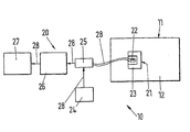
- the storage device 10 initially consists of a storage container 11 in which Hydrogen is stored. To increase the storage capacity is located a storage mass 12 within the storage container 11.
- the storage mass 12 consists of a number of conglomerates formed from carbon nanofibers are.
- the storage device 10 has a device 20 for measuring the Level of the hydrogen stored in the storage container 11.
- the Measuring device 20 is designed such that it the nuclear magnetic resonance of the Can measure hydrogen.
- the measuring device 20 has a measuring head 21 which is formed from a permanent magnet 23 and a measuring coil 22.
- the Permanent magnet 23 is a horseshoe magnet that encloses the measuring coil 22. He is used to generate a constant static magnetic field. Via the measuring coil 22 we coupled an alternating electromagnetic field with radio frequency, the Field lines of the static magnetic field and the alternating electromagnetic field stand perpendicular to each other.
- the electromagnetic alternating field is generated in a transmitter 24, which has a Bridge circuit 25 and corresponding lines 28 with the measuring coil 22 of the Measuring head 21 is connected.
- the bridge circuit 25 conducts the values of the measured by the measuring head 21 nuclear magnetic resonance, which is determined in the manner described above were, via an amplifier 26 in a display device 27, the present Case is designed as a pointer instrument.
- the individual elements are in turn connected to one another via lines 28.
- the bridge circuit prevents 25 that signals from the transmitter 24 are forwarded directly to the amplifier 26, which could cause damage to this device.
- the individual units described above can also be designed as an integrated circuit or manufactured using microsystem technology and be assembled.
- the level of hydrogen in a tank system, one with carbon nanofibers has as the storage mass 12 filled storage container 11, with the Measuring device 20 can be measured.
- the Permanent magnet 23 of the measuring head 21 a constant static magnetic field generated.
- the nuclear magnetic spins of the hydrogen are created by the static magnetic field parallel or anti-parallel to the applied static magnetic field, creating two different energy levels with a certain energy difference arise.
- the measuring head Around to be able to make a precise statement about the level of the hydrogen the measuring head of a quantity representative of the entire storage container 11 of the hydrogen and also the storage mass 12.
- a variable electromagnetic is in the measuring head 21 via the measuring coil 22 Alternating field coupled with radio frequency, which was previously generated in the transmitter 24.
- the variation of the alternating electromagnetic field takes place by changing the Frequency.
- the measuring coil 22 and the permanent magnet 23 must be in this way to one another be aligned that the field lines of the static magnetic field and electromagnetic alternating field are perpendicular to each other.
- nuclear spins of the Hydrogen By supplying the alternating electromagnetic field, nuclear spins of the Hydrogen is transported from the lower to the upper energy level, whereby the energy of the electromagnetic alternating field is absorbed.
- the absorbed energy is therefore directly proportional to the number of nuclear spins. For the called tank system this means that the absorbed energy is always direct is proportional to the fill level of the storage container 11, if within the Measuring coil 21 is a representative part of the storage mass and the stored Hydrogen.
- the values of the nuclear magnetic resonance of the measuring head 21 measured Hydrogen, or the values for the absorbed energy, are determined by the Bridge circuit 25 and the amplifier 26 to the trained as a pointer instrument Display device 27 forwarded.
- the measured values can be sent to the Pointer instrument 27 in another suitable device (not shown), For example, a computer or the like, processed and processed become.
- a great advantage of the storage device according to the invention can be seen in the fact that the measuring head for performing the measurement of nuclear magnetic resonance completely is independent of the shape and size of the respective storage container. So that is an inexpensive and quality-assured series production of this component possible.
- the placement of the measuring head in the storage container ensures one very good protection against damage to the measuring head.
Landscapes
- Physics & Mathematics (AREA)
- General Physics & Mathematics (AREA)
- Spectroscopy & Molecular Physics (AREA)
- High Energy & Nuclear Physics (AREA)
- Condensed Matter Physics & Semiconductors (AREA)
- Engineering & Computer Science (AREA)
- Electromagnetism (AREA)
- Power Engineering (AREA)
- Thermal Sciences (AREA)
- Fluid Mechanics (AREA)
- Filling Or Discharging Of Gas Storage Vessels (AREA)
Abstract
Description
Claims (20)
- Vorrichtung zum Speichern eines gasförmigen Mediums mit einem Speicherbehälter (11) zur Aufnahme des gasförmigen Mediums, wobei der Speicherbehälter(11) mit einer Speichermasse (12) zum Speichern des gasförmigen Mediums gefüllt ist,
dadurch gekennzeichnet,daß eine Meßvorrichtung zur Messung der kernmagnetischen Resonanz des im Speicherbehälter (11) befindlichen gasförmigen Mediums vorgesehen ist, wobei die Meßvorrichtung ein statisches Magnetfeld und ein elektromagnetisches Wechselfeld erzeugt, dessen Feldlinien senkrecht auf den Feldlinien des statischen Magnetfeldes stehen,daß die Meßvorrichtung einen Meßkopf (21) aufweist, in dem das statische Magnetfeld und das elektromagnetische Wechselfeld erzeugt werden, unddaß der Meßkopf (21) innerhalb des Speicherbehälters (11) oder in einem mit dem Speicherbehälter (11) strömungstechnisch verbundenen Meßrohr in der Weise angeordnet ist, daß er ein Teilvolumen erfaßt, wobei das Teilvolumen hinsichtlich der Füllung mit der Speichermasse und dem gespeicherten gasförmigen Medium repräsentativ ist für den gesamten Speicherbehälter (11). - Vorrichtung nach Anspruch 1,
dadurch gekennzeichnet, daß die Vorrichtung (20) ausgebildet ist zur Messung der kernmagnetischen Resonanz des gespeicherten Mediums nach der CW-Methode. - Vorrichtung nach Anspruch 1,
dadurch gekennzeichnet, daß die Vorrichtung (20) ausgebildet ist zur Bestimmung der kernmagnetischen Resonanz des gespeicherten Mediums nach der Fouriertransform-Methode. - Vorrichtung nach Anspruch 1,
dadurch gekennzeichnet, daß die Vorrichtung (20) ausgebildet ist zur Bestimmung der kernmagnetischen Resonanz des gespeicherten Mediums bei einem konstanten statischen Magnetfeld und einem konstanten elektromagnetischen Wechselfeld. - Vorrichtung nach einem der Ansprüche 1 bis 4,
dadurch gekennzeichnet, daß der Meßkopf (21) eine Meßspule (22) aufweist und daß das elektromagnetische Wechselfeld über die Meßspule (21) eingekoppelt oder einkoppelbar ist. - Vorrichtung nach einem der Ansprüche 1 bis 5,
dadurch gekennzeichnet, daß der Meßkopf (21) einen Elektromagneten, insbesondere einen supraleitenden Magneten, und/oder einen Permanentmagneten (23) aufweist, über den/die das statische Magnetfeld erzeugt oder erzeugbar ist. - Vorrichtung nach einem der Ansprüche 1 bis 6,
dadurch gekennzeichnet, daß das elektromagnetische Wechselfeld eine Frequenz im Bereich von 103 bis 109 Hz, vorzugsweise im Bereich der Radiofrequenz, aufweist. - Vorrichtung nach einem der Ansprüche 1 bis 7,
dadurch gekennzeichnet, daß ein Sender (24) zum Erzeugen des elektromagnetischen Wechselfelds vorgesehen ist. - Vorrichtung nach einem der Ansprüche 1 bis 8,
dadurch gekennzeichnet, daß eine Anzeigeeinrichtung (27) vorgesehen ist. - Vorrichtung nach Anspruch 9,
dadurch gekennzeichnet, daß der Anzeigeeinrichtung (27) ein Verstärker (26) vorgeschaltet ist. - Vorrichtung nach einem der Ansprüche 9 oder 10, sofern sie sich auf Anspruch 8 beziehen
dadurch gekennzeichnet, daß eine Brückenschaltung (25) vorgesehen ist, über die der Meßkopf (21), der Sender (24) und die Anzeigeeinrichtung (27) miteinander gekoppelt sind. - Vorrichtung nach einem der Ansprüche 1 - 11,
dadurch gekennzeichnet,
daβ sie eine Einrichtung zur Erfassung der Temperatur des Mediums umfaßt. - Vorrichtung nach einem der Ansprüche 1 bis 12,
dadurch gekennzeichnet, daß die Speichermasse (12) aus Carbon-Nanostrukturen, insbesondere aus Nanofasem, Nanoröhrchen oder Nanoschuppen gebildet ist. - Vorrichtung nach Anspruch 13,
dadurch gekennzeichnet, daß die Carbon-Nanostrukturen gerichtete Struktur aufweisen und/oder bilden. - Vorrichtung nach Anspruch 13 oder 14,
dadurch gekennzeichnet, daß die Carbon-Nanostrukturen zu größeren zusammenhängenden Konglomeraten verbunden sind. - Vorrichtung nach einem der Ansprüche 1 bis 15,
dadurch gekennzeichnet, daß die Speichermasse (12) aus einer Anzahl von einzelnen zusammenhängenden Konglomeraten zusammengesetzt ist. - Vorrichtung nach Anspruch 15 oder 16,
dadurch gekennzeichnet, daß zumindest einzelne Konglomerate mit gegenüber der Scheindichte der ursprünglich losen Carbon-Nanostrukturen erhöhter Scheindichte verdichtet sind, wobei die Scheindichte das auf das Volumen des konglomerats bezogene gewicht ist. - Vorrichtung nach einem der Ansprüche 1 bis 17,
dadurch gekennzeichnet, daß das gasförmiger Medium Wasserstoff ist. - Verfahren zum Messen des Füllstands eines gasförmigen Mediums in einer Speichervorrichtung nach einem der Ansprüche 1 bis 18, mit folgendes Schritten:a) Erzeugen eines statischen Magnetfelds und eines elektromagnetischen Wechsetfelds im Meßkopf, der im Speicherbehälter oder in einem mit dem Speicherbehälter strömungstechnisch verbundenen Meßrohr angeordnet ist;b) Messen der kernmagnetischen Resonanz des gespeicherten Mediums über den Meßkopf, wobei der Meßkopf von einer repräsentativen Menge der Speichermasse und des gespeicherten gasförmigen Mediums durchdrungen ist; undc) Anzeigen eines dem Füllstand entsprechenden Ergebnisses auf der Basis der gemessenen Werte in der Anzeigeeinrichtung.
- Verfahren nach Anspruch 19,
dadurch gekennzeichnet, daß die gemessenen Werte der kernmagnetischen Resonanz des gespeicherten Mediums vor dem Anzeigen in der Anzeigeeinrichtung aufbereitet und/oder weiterverarbeitet werden.
Applications Claiming Priority (3)
| Application Number | Priority Date | Filing Date | Title |
|---|---|---|---|
| DE19838664 | 1998-08-19 | ||
| DE19838664A DE19838664C2 (de) | 1998-08-19 | 1998-08-19 | Vorrichtung zum Speichern eines gasförmigen Mediums und Verfahren zum Messen des Füllstands eines gasförmigen Mediums in einer Speichervorrichtung |
| PCT/DE1999/002503 WO2000011438A1 (de) | 1998-08-19 | 1999-08-06 | Vorrichtung und verfahren zum messen der menge eines gasförmigen mediums in einem speicherbehälter |
Publications (2)
| Publication Number | Publication Date |
|---|---|
| EP1110060A1 EP1110060A1 (de) | 2001-06-27 |
| EP1110060B1 true EP1110060B1 (de) | 2003-02-19 |
Family
ID=7878689
Family Applications (1)
| Application Number | Title | Priority Date | Filing Date |
|---|---|---|---|
| EP99953525A Expired - Lifetime EP1110060B1 (de) | 1998-08-19 | 1999-08-06 | Vorrichtung und verfahren zum messen der menge eines gasförmigen mediums in einem speicherbehälter |
Country Status (7)
| Country | Link |
|---|---|
| US (1) | US6541974B1 (de) |
| EP (1) | EP1110060B1 (de) |
| JP (1) | JP2002523734A (de) |
| AU (1) | AU1027100A (de) |
| DE (2) | DE19838664C2 (de) |
| ES (1) | ES2188262T3 (de) |
| WO (1) | WO2000011438A1 (de) |
Families Citing this family (4)
| Publication number | Priority date | Publication date | Assignee | Title |
|---|---|---|---|---|
| US20050124151A1 (en) * | 2003-12-04 | 2005-06-09 | Taiwan Semiconductor Manufacturing Co. | Novel method to deposit carbon doped SiO2 films with improved film quality |
| US7002346B2 (en) * | 2004-05-03 | 2006-02-21 | The Boc Group, Inc. | Method for accurate determination of sample temperature in a NMR check weighing system |
| US8673436B2 (en) * | 2006-12-22 | 2014-03-18 | Southwest Research Institute | Nanoengineered material for hydrogen storage |
| CN116067453B (zh) * | 2023-03-03 | 2023-06-20 | 华中科技大学 | 一种磁耦合型多相态导纳识别的储气库测距系统及方法 |
Family Cites Families (7)
| Publication number | Priority date | Publication date | Assignee | Title |
|---|---|---|---|---|
| US4785245A (en) * | 1986-09-12 | 1988-11-15 | Engineering Measurement Company | Rapid pulse NMR cut meter |
| US5122746A (en) * | 1990-06-12 | 1992-06-16 | Gas Research Institute | Hydrocarbon gas measurements using nuclear magnetic resonance |
| US5458784A (en) * | 1990-10-23 | 1995-10-17 | Catalytic Materials Limited | Removal of contaminants from aqueous and gaseous streams using graphic filaments |
| GB9300318D0 (en) * | 1993-01-08 | 1993-03-03 | Oxford Analytical Instr Ltd | Improvements relating to sample monitoring |
| GB9523846D0 (en) * | 1995-11-22 | 1996-01-24 | Secretary Trade Ind Brit | Nuclear magnetic resonance gauging device |
| DE19745549C2 (de) * | 1997-10-10 | 1999-11-04 | Mannesmann Ag | Gasspeicher |
| US6333629B1 (en) * | 1999-07-22 | 2001-12-25 | Intermagnetics General Corporation | Method for non-invasively and without contact, inspecting foil enclosed packages, using magnetic resonance techniques |
-
1998
- 1998-08-19 DE DE19838664A patent/DE19838664C2/de not_active Expired - Fee Related
-
1999
- 1999-08-06 EP EP99953525A patent/EP1110060B1/de not_active Expired - Lifetime
- 1999-08-06 WO PCT/DE1999/002503 patent/WO2000011438A1/de not_active Ceased
- 1999-08-06 DE DE59904346T patent/DE59904346D1/de not_active Expired - Fee Related
- 1999-08-06 ES ES99953525T patent/ES2188262T3/es not_active Expired - Lifetime
- 1999-08-06 JP JP2000566646A patent/JP2002523734A/ja active Pending
- 1999-08-06 AU AU10271/00A patent/AU1027100A/en not_active Abandoned
- 1999-08-06 US US09/763,300 patent/US6541974B1/en not_active Expired - Fee Related
Also Published As
| Publication number | Publication date |
|---|---|
| JP2002523734A (ja) | 2002-07-30 |
| DE19838664A1 (de) | 2000-03-23 |
| DE19838664C2 (de) | 2000-10-12 |
| ES2188262T3 (es) | 2003-06-16 |
| DE59904346D1 (de) | 2003-03-27 |
| US6541974B1 (en) | 2003-04-01 |
| AU1027100A (en) | 2000-03-14 |
| WO2000011438A1 (de) | 2000-03-02 |
| EP1110060A1 (de) | 2001-06-27 |
Similar Documents
| Publication | Publication Date | Title |
|---|---|---|
| DE3036347C2 (de) | ||
| DE2611497A1 (de) | Verfahren und vorrichtung zur gyromagnetischen zeugmatographie | |
| DE69411419T2 (de) | Verbesserte NMR-Sonde mit B1-Gradientenspulen | |
| EP0184225A2 (de) | Kernspin-Tomographie-Verfahren | |
| DE3323657A1 (de) | Spulenanordnung | |
| DE1908881A1 (de) | Verfahren und Vorrichtung zum Messen der Masse einer Fluessigkeit oder des veraenderlichen Volumens eines metallischen Innenbehaelters in einem metallischen aeusseren Behaelter | |
| EP0167059A2 (de) | Kernspin-Tomographiegerät | |
| EP0105220A1 (de) | Gerät zur Erzeugung von Bildern eines Untersuchungsobjektes mit magnetischer Kernresonanz | |
| EP3036511B1 (de) | Kernmagnetisches durchflussmessgerät und verfahren zum betreiben von kernmagnetischen durchflussmessgeräten | |
| DE3043810A1 (de) | Vorrichtung zur ueberwachung des tintenvorrats in tintenschreibeinrichtungen | |
| WO1989011646A1 (fr) | Spectrometre rmn avec changeur d'echantillons | |
| DE19838664C2 (de) | Vorrichtung zum Speichern eines gasförmigen Mediums und Verfahren zum Messen des Füllstands eines gasförmigen Mediums in einer Speichervorrichtung | |
| DE19860488C1 (de) | Impulssequenz für ein Kernspintomographiegerät | |
| EP0350120A1 (de) | Verfahren und Kernspinresonanzanordnung zur Schnellbestimmung der Transversal-Relaxationszeit T2 | |
| DE102005037369A1 (de) | Magnetresonanz-Bildgebungsverfahren mit Anwendung der True-FISP-Sequenz und sequentieller Erfassung der MR-Bilder mehrerer Schichten eines Messobjekts | |
| DE4204294A1 (de) | Verfahren und vorrichtung zum messen von luecken zwischen benachbarten brennstoffstaeben einer brennstoffkassette | |
| DE69826742T2 (de) | Gerät und Verfahren zur Erzeugung von Gradientenmagnetfeldern für hochauflösende NMR-Experimente im magischen Winkel | |
| DE3908392A1 (de) | Verfahren zur lokalisierten magnetischen resonanz-spektroskopie (losy) und zur schichtselektiven anregung von transversalmagnetisierungen (slise) | |
| EP0199202A1 (de) | Kernspinresonanzgerät | |
| WO1990013826A1 (de) | Verfahren zur aufnahme von spinresonanzspektren | |
| EP3517929B1 (de) | Verfahren zur messung der dichte eines durch ein rohr strömenden oder sich in einem rohr befindlichen mediums, messgerät und datenträger | |
| DE3838792A1 (de) | Kernspintomographieverfahren zur bestimmung der kernmagnetisierung in einer anzahl paralleler schichten | |
| DE102022202228A1 (de) | Gyroskop-Sensor mit Dampfzelle | |
| EP4083581A1 (de) | Verfahren zum bestimmen eines flüssigkeitsanteils eines strömenden mediums mit einem kernmagnetischen durchflussmessgerät | |
| DE1498973A1 (de) | Verfahren zum Analysieren einer Mischung |
Legal Events
| Date | Code | Title | Description |
|---|---|---|---|
| PUAI | Public reference made under article 153(3) epc to a published international application that has entered the european phase |
Free format text: ORIGINAL CODE: 0009012 |
|
| 17P | Request for examination filed |
Effective date: 20010206 |
|
| AK | Designated contracting states |
Kind code of ref document: A1 Designated state(s): AT BE CH CY DE DK ES FI FR GB GR IE IT LI LU MC NL PT SE Kind code of ref document: A1 Designated state(s): DE ES FR GB IT SE |
|
| AX | Request for extension of the european patent |
Free format text: AL;LT;LV;MK;RO;SI |
|
| GRAH | Despatch of communication of intention to grant a patent |
Free format text: ORIGINAL CODE: EPIDOS IGRA |
|
| RTI1 | Title (correction) |
Free format text: DEVICE AND METHOD FOR STORING A GASEOUS MEDIUM IN A STORAGE CONTAINER |
|
| GRAH | Despatch of communication of intention to grant a patent |
Free format text: ORIGINAL CODE: EPIDOS IGRA |
|
| RAP1 | Party data changed (applicant data changed or rights of an application transferred) |
Owner name: VODAFONE AG |
|
| GRAA | (expected) grant |
Free format text: ORIGINAL CODE: 0009210 |
|
| AK | Designated contracting states |
Designated state(s): DE ES FR GB IT SE |
|
| REG | Reference to a national code |
Ref country code: GB Ref legal event code: FG4D Free format text: NOT ENGLISH |
|
| REG | Reference to a national code |
Ref country code: IE Ref legal event code: FG4D Free format text: GERMAN |
|
| REF | Corresponds to: |
Ref document number: 59904346 Country of ref document: DE Date of ref document: 20030327 Kind code of ref document: P |
|
| GBT | Gb: translation of ep patent filed (gb section 77(6)(a)/1977) |
Effective date: 20030329 |
|
| ET | Fr: translation filed | ||
| RAP2 | Party data changed (patent owner data changed or rights of a patent transferred) |
Owner name: VODAFONE HOLDING GMBH |
|
| REG | Reference to a national code |
Ref country code: ES Ref legal event code: FG2A Ref document number: 2188262 Country of ref document: ES Kind code of ref document: T3 |
|
| LTIE | Lt: invalidation of european patent or patent extension |
Effective date: 20030219 |
|
| REG | Reference to a national code |
Ref country code: IE Ref legal event code: FD4D Ref document number: 1110060E Country of ref document: IE |
|
| PLBE | No opposition filed within time limit |
Free format text: ORIGINAL CODE: 0009261 |
|
| STAA | Information on the status of an ep patent application or granted ep patent |
Free format text: STATUS: NO OPPOSITION FILED WITHIN TIME LIMIT |
|
| 26N | No opposition filed |
Effective date: 20031120 |
|
| PGFP | Annual fee paid to national office [announced via postgrant information from national office to epo] |
Ref country code: GB Payment date: 20040722 Year of fee payment: 6 |
|
| PGFP | Annual fee paid to national office [announced via postgrant information from national office to epo] |
Ref country code: FR Payment date: 20040819 Year of fee payment: 6 |
|
| PGFP | Annual fee paid to national office [announced via postgrant information from national office to epo] |
Ref country code: SE Payment date: 20040825 Year of fee payment: 6 |
|
| PGFP | Annual fee paid to national office [announced via postgrant information from national office to epo] |
Ref country code: ES Payment date: 20040826 Year of fee payment: 6 |
|
| PG25 | Lapsed in a contracting state [announced via postgrant information from national office to epo] |
Ref country code: IT Free format text: LAPSE BECAUSE OF NON-PAYMENT OF DUE FEES;WARNING: LAPSES OF ITALIAN PATENTS WITH EFFECTIVE DATE BEFORE 2007 MAY HAVE OCCURRED AT ANY TIME BEFORE 2007. THE CORRECT EFFECTIVE DATE MAY BE DIFFERENT FROM THE ONE RECORDED. Effective date: 20050806 Ref country code: GB Free format text: LAPSE BECAUSE OF NON-PAYMENT OF DUE FEES Effective date: 20050806 |
|
| PG25 | Lapsed in a contracting state [announced via postgrant information from national office to epo] |
Ref country code: SE Free format text: LAPSE BECAUSE OF NON-PAYMENT OF DUE FEES Effective date: 20050807 |
|
| PG25 | Lapsed in a contracting state [announced via postgrant information from national office to epo] |
Ref country code: ES Free format text: LAPSE BECAUSE OF NON-PAYMENT OF DUE FEES Effective date: 20050808 |
|
| PGFP | Annual fee paid to national office [announced via postgrant information from national office to epo] |
Ref country code: DE Payment date: 20051026 Year of fee payment: 7 |
|
| EUG | Se: european patent has lapsed | ||
| GBPC | Gb: european patent ceased through non-payment of renewal fee |
Effective date: 20050806 |
|
| PG25 | Lapsed in a contracting state [announced via postgrant information from national office to epo] |
Ref country code: FR Free format text: LAPSE BECAUSE OF NON-PAYMENT OF DUE FEES Effective date: 20060428 |
|
| REG | Reference to a national code |
Ref country code: FR Ref legal event code: ST Effective date: 20060428 |
|
| REG | Reference to a national code |
Ref country code: ES Ref legal event code: FD2A Effective date: 20050808 |
|
| PG25 | Lapsed in a contracting state [announced via postgrant information from national office to epo] |
Ref country code: DE Free format text: LAPSE BECAUSE OF NON-PAYMENT OF DUE FEES Effective date: 20070301 |