EP1109604B1 - Device for fixing a shoe to a sports article - Google Patents
Device for fixing a shoe to a sports article Download PDFInfo
- Publication number
- EP1109604B1 EP1109604B1 EP99940232A EP99940232A EP1109604B1 EP 1109604 B1 EP1109604 B1 EP 1109604B1 EP 99940232 A EP99940232 A EP 99940232A EP 99940232 A EP99940232 A EP 99940232A EP 1109604 B1 EP1109604 B1 EP 1109604B1
- Authority
- EP
- European Patent Office
- Prior art keywords
- connecting member
- base
- binding device
- shoe
- rocker bar
- Prior art date
- Legal status (The legal status is an assumption and is not a legal conclusion. Google has not performed a legal analysis and makes no representation as to the accuracy of the status listed.)
- Expired - Lifetime
Links
Images

Classifications
-
- A—HUMAN NECESSITIES
- A63—SPORTS; GAMES; AMUSEMENTS
- A63C—SKATES; SKIS; ROLLER SKATES; DESIGN OR LAYOUT OF COURTS, RINKS OR THE LIKE
- A63C1/00—Skates
- A63C1/22—Skates with special foot-plates of the boot
- A63C1/28—Pivotally-mounted plates
-
- A—HUMAN NECESSITIES
- A63—SPORTS; GAMES; AMUSEMENTS
- A63C—SKATES; SKIS; ROLLER SKATES; DESIGN OR LAYOUT OF COURTS, RINKS OR THE LIKE
- A63C9/00—Ski bindings
- A63C9/20—Non-self-releasing bindings with special sole edge holders instead of toe-straps
Definitions
- WO 96/37269 aims to solve the same problem, namely to maximize the thrust effort or momentum when practicing sport by proposing a multiple construction chassis in which the chassis are able to pivot and translate with respect to one another.
- Document EP 890 379 which describes a fastening provided with a surface connection member convex support with a link hinged forward, is an art only prior to title of Article 54 (3) EPC. It is the same for document EP 914 844 which does not include no curved support ramp.
- the construction according to the invention therefore makes it possible to reconcile guidance and precision of the maximum gesture with equally maximum power transmission.
- this fixing device is very simple. In the absence of any effort from on the part of the user, the beam 30 is pressed against the base 11 under the effect of the means of elastic return 40 (see Figures 3 and 4).
- the beam 30 and the link 20 simultaneously perform a clockwise rotation (arrows R) around their respective axes 31, 21, beam 30 pivoting moreover on the base 11 according to a succession of supports constituting as many axes of instantaneous rotation and moving along the curved ramp 34.
Abstract
Description
La présente invention a pour objet un dispositif de fixation articulée d'une chaussure à un article de sport, notamment sport de glisse tel que patin à glace, à roulettes, ski de fond,...etc.The subject of the present invention is a device for articulated attachment of a shoe to a sporting goods, in particular sliding sports such as ice skating, roller skating, cross country skiing, etc.
Par le FR 2 659 534 il est déjà connu d'avoir une liaison articulée d'une chaussure à un
article de sport tel que patin à roulettes, patin à glace, afin d'augmenter le couple d'impulsion
lors de la pratique du sport. Le document prévoit soit une articulation de la chaussure sur
l'article de sport au niveau de l'emplacement du gros orteil dans la chaussure de façon à
permettre une rotation maximale de la chaussure, soit une articulation au niveau de la zone
d'articulation métatarsophalangienne du pied de façon à garantir un bon déroulement du pied.By
Dans le premier cas, la rotation maximale de la chaussure permet de maximiser le couple d'impulsion de la jambe lors de la phase motrice mais s'effectue au détriment de la précision et du guidage de la chaussure, notamment avec une semelle souple nécessaire à un bon déroulement du pied.In the first case, the maximum rotation of the shoe makes it possible to maximize the torque momentum of the leg during the motor phase but takes place at the expense of precision and guiding the shoe, in particular with a flexible sole necessary for good unwinding of the foot.
Dans le second cas, l'articulation au niveau de l'axe d'articulation métatarsophalangienne permet d'améliorer le guidage au détriment cependant du déroulement du pied et du couple d'impulsion.In the second case, the articulation at the level of the metatarsophalangeal articulation axis makes it possible to improve the guidance at the expense however of the course of the foot and the couple pulse.
Le WO 96/37269 vise à résoudre le même problème à savoir maximiser l'effort de poussée ou couple d'impulsion lors de la pratique du sport en proposant une construction à multiple châssis dans laquelle les châssis sont aptes à pivoter et à translater l'un par rapport à l'autre.WO 96/37269 aims to solve the same problem, namely to maximize the thrust effort or momentum when practicing sport by proposing a multiple construction chassis in which the chassis are able to pivot and translate with respect to one another.
Les modes de réalisation préférés de ce WO 96/37269 comprennent au moins quatre biellettes articulées et translatables les unes par rapport aux autres. Il s'ensuit une construction extrêmement compliquée, lourde, coûteuse, difficile à mettre en oeuvre et fragile, notamment si le sport doit être pratiqué dans un environnement agressif (froid, neige, poussières,...etc.).Preferred embodiments of this WO 96/37269 include at least four articulated and translatable rods relative to each other. It follows a construction extremely complicated, heavy, expensive, difficult to implement and fragile, in particular if the sport must be practiced in an aggressive environment (cold, snow, dust, etc.).
Le WO 96/37269 propose également une autre construction mettant en oeuvre des engrenages et donc également extrêmement compliquée et coûteuse à réaliser, et de plus très sensible aux salissures, froid, neige,...etc.WO 96/37269 also proposes another construction using gears and therefore also extremely complicated and expensive to produce, and moreover very sensitive to dirt, cold, snow, ... etc.
Par ailleurs, chacune des constructions du WO 96/37269 ne peut autoriser que des débattements de la chaussure assez limités, et compris entre 20° et 48°, ces faibles débattements étant préjudiciables à une bonne pratique de l'activité.Furthermore, each of the constructions of WO 96/37269 can only authorize fairly limited shoe travel, and between 20 ° and 48 °, these low deflections being detrimental to a good practice of the activity.
Le document EP 890 379, qui décrit une fixation munie d'un organe de liaison à surface d'appui convexe avec une biellette articulée vers l'avant, est un art antérieur uniquement au titre de l'article 54(3) CBE. Il en est de même pour le document EP 914 844 qui ne comporte pas de rampe d'appui curviligne.Document EP 890 379, which describes a fastening provided with a surface connection member convex support with a link hinged forward, is an art only prior to title of Article 54 (3) EPC. It is the same for document EP 914 844 which does not include no curved support ramp.
Le but de la présente invention est de remédier aux inconvénients ci-avant et de fournir un dispositif de fixation amélioré qui permette notamment de maximiser le couple d'impulsion transmis par la jambe, tout en étant compatible avec un bon guidage de la chaussure, un grand débattement et une bonne précision du geste. The object of the present invention is to remedy the above drawbacks and to provide a improved fixing device which allows in particular to maximize the impulse torque transmitted by the leg, while being compatible with good guidance of the shoe, a large movement and good precision of the gesture.
Un autre but est également de fournir un dispositif de fixation qui soit de construction simple, peu chère, non encombrante et qui soit peu sensible aux conditions extérieures, et notamment au froid et à la neige.Another object is also to provide a fixing device which is of construction simple, inexpensive, not bulky and not very sensitive to external conditions, and especially in cold and snow.
Ce but est atteint dans le dispositif de fixation d'une chaussure à un article de sport, selon l'invention, par le fait qu'il comporte une embase destinée à être fixée sur l'article de sport, un organe de liaison à la chaussure et une biellette de liaison de l'organe de liaison à l'embase, la biellette étant articulée d'une part sur l'embase, et d'autre part sur l'organe de liaison et plus particulièrement par le fait que l'organe de liaison comporte, à l'avant, une rampe d'appui curviligne apte à coopérer avec l'embase lors du pivotement de l'organe de liaison.This object is achieved in the device for attaching a shoe to a sporting article, according to the invention, by the fact that it comprises a base intended to be fixed on the sports article, a shoe binding and a link rod from the link member to the base, the link being articulated on the one hand on the base, and on the other hand on the connecting member and more particularly by the fact that the connecting member comprises, at the front, a curvilinear support ramp capable of cooperating with the base during pivoting of the connecting member.
En effet, l'organe de liaison, fixé sur une zone avant de la chaussure, rigidifie celle-ci et permet donc de préserver la précision de mouvement souhaitée, tandis qu'une construction à une seule biellette est simple, minimale, peu encombrante et peu coûteuse.Indeed, the connecting member, fixed on a front zone of the shoe, stiffens the latter and therefore allows the desired movement precision to be preserved, while a single link is simple, minimal, space-saving and inexpensive.
Par ailleurs, une telle construction est peu sensible au froid et à la neige.Furthermore, such a construction is not very sensitive to cold and snow.
De toute façon, l'invention sera mieux comprise et d'autres caractéristiques de celle-ci seront mises en évidence à l'aide de la description qui suit en référence au dessin schématique annexé représentant à titre d'exemples non limitatifs plusieurs modes de réalisation préférés et dans lequel :
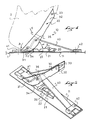
- la figure 1 est une vue de côté du dispositif de fixation selon l'invention en position soulevée, la chaussure étant représentée en traits mixtes,
- la figure 2 est une vue en perspective arrière du dispositif de fixation de la figure 1,
- la figure 3 est une vue similaire à la figure 2 en position basse,
- la figure 4 est une vue similaire à la figure 1 en position basse.
- FIG. 1 is a side view of the fastening device according to the invention in the raised position, the shoe being shown in phantom,
- FIG. 2 is a rear perspective view of the fixing device of FIG. 1,
- FIG. 3 is a view similar to FIG. 2 in the low position,
- Figure 4 is a view similar to Figure 1 in the low position.
La figure 1 montre le dispositif de fixation 10 selon l'invention assurant la liaison d'une
chaussure 2 et d'un article de sport 1.Figure 1 shows the
Le dispositif de fixation est constitué d'une embase 11 fixée sur la face supérieure de
l'article de sport 1, d'une biellette 20 articulée sur l'embase 11 autour d'un axe transversal 21,
d'un organe de liaison 30, articulé selon un axe transversal 31 sur la biellette 20, et d'un moyen
de rappel élastique 40, constitué en l'occurrence par une bande de matériau élastique tel que
du caoutchouc ou du pebax.The fixing device consists of a
Ainsi que le montre plus particulièrement la figure 2, l'organe de liaison 30 se présente
sous la forme d'une poutre constituée de deux biellettes 32, entretoisées d'une part à l'avant par
l'axe transversal 31 d'articulation sur la biellette 20, et d'autre part par un axe 33 disposé à
l'arrière des deux biellettes. Ces axes 31, 33, servent également de moyens d'ancrage sur la
chaussure et sont destinés à coopérer avec des moyens complémentaires de la semelle ou de la
tige de ladite chaussure (non représentés sur le dessin). D'autres moyens d'ancrage peuvent
bien évidemment être envisagés et notamment la poutre 30 peut être intégrée dans la semelle
de la chaussure, par exemple par surmoulage, lors de la fabrication ou être fixée à celle-ci par
des vis, rivets,...etc.As shown more particularly in Figure 2, the connecting
Des moyens d'ancrage amovibles, c'est-à-dire permettant un enlèvement rapide de la chaussure peuvent également être prévus.Removable anchoring means, that is to say allowing rapid removal of the shoe can also be provided.
L'organe de liaison 30 peut également être réalisé de façon différente et peut notamment
être constitué par une poutre en une seule pièce, en tôle emboutie, ou en autre matériau
synthétique,...etc. The connecting
La poutre définie par l'organe de liaison 30 a de préférence une longueur correspondant à
celle de la zone avant, qui s'étend depuis l'extrémité avant jusqu'à la zone d'articulation
métatarsophalangienne, d'une chaussure, soit à peu près le tiers de la longueur d'une
chaussure.The beam defined by the connecting
Cette poutre 30 a non seulement pour but de réaliser la liaison de la chaussure avec l'article
de sport, mais également de rigidifier la chaussure de façon à permettre un meilleur guidage et
transmission des efforts lors du soulèvement de celle-ci lors de la pratique du sport.This
Bien entendu, la poutre 30 peut également avoir une toute autre forme et être notamment
plus longue ou plus courte.Of course, the
La partie avant de chacune des biellettes 32 présente un profil curviligne 34 en forme de
rampe par lequel chacune de ces biellettes 32 est en appui sur l'embase 11. Cette rampe
curviligne 34 coopère avec ladite embase 11 lors du pivotement de la chaussure de façon à
reproduire un mouvement de rotation et translation correspondant au mouvement de
déroulement du pied au niveau du gros orteil.The front part of each of the
Cette construction permet de reproduire un mouvement de déroulement du pied, comme si
l'axe d'articulation de la chaussure était fixée à l'extrémité avant de celle-ci, tout en conservant
la précision d'une semelle rigide, puisque la semelle est rigidifiée en fait par la poutre 30, et
ceci jusqu'au bout des orteils, c'est-à-dire en offrant un couple d'impulsion maximal.This construction makes it possible to reproduce an unwinding movement of the foot, as if
the axis of articulation of the shoe was fixed to the front end thereof, while retaining
the precision of a rigid sole, since the sole is in fact stiffened by the
La construction selon l'invention permet donc de concilier un guidage et une précision du geste maximales avec une transmission de puissance également maximale.The construction according to the invention therefore makes it possible to reconcile guidance and precision of the maximum gesture with equally maximum power transmission.
Une bande de caoutchouc 40 est fixée en 41 et 42, par exemple par des vis, sur l'embase 11,
à l'avant et à l'arrière de la poutre 30 et de part et d'autre de sa zone d'appui sur l'article de
sport. Cette bande 40 passe par ailleurs par dessus un axe 35, ou entretoise, disposé
transversalement entre les deux biellettes 32, à l'arrière de la rampe 34.A
Ainsi disposée, la bande de caoutchouc 40 exerce au niveau de l'axe 35 sur la poutre 30, et
donc sur la chaussure 2 qui lui est liée, un effort permanent F de rappel élastique vers la
surface supérieure 1 de l'article de sport. Cette construction aide au ramené de l'article de sport
contre la semelle de la chaussure lors de la fin de la phase d'impulsion et évite toute
interférence de celui-ci avec la surface sur laquelle se pratique ledit sport.Thus disposed, the
Dans ce contexte, il est préférable que le point 35 d'application de l'effort F soit situé à
l'arrière de la rampe 34, mais en avant de l'axe d'articulation 21 de la biellette 20, pour éviter
une position d'équilibre de la chaussure soulevée par rapport à l'article de sport 1 en l'absence
de sollicitations de la part de l'utilisateur.In this context, it is preferable that the point of application of the force F is located at
the rear of the
Selon le cas et le type de sport pratiqué une position plus en avant de ce point d'application
35 de l'effort F peut également être envisagée. La bande élastique 40 peut être remplacée par
tout autre moyen de rappel élastique, et notamment ressort, produisant le même effet.Depending on the case and the type of sport practiced a position further forward from this point of
La biellette 20 se présente sous la forme d'une pièce monobloc dont les extrémités sont
constituées de deux bras 22 entretoisés d'une part par l'axe de pivotement 31 de la poutre 30,
et d'autre part par l'axe d'articulation 21 de la biellette sur l'embase 11, chacun de ces axes 21,
31, étant disposé à chacune des extrémités de ladite biellette 20, l'axe 21 étant disposé à
l'arrière de l'axe 31. Bien entendu, la biellette 20 peut également être constituée de plusieurs
parties.The
La longueur de la biellette 20, c'est-à-dire la distance entre les axes d'articulation 21, 31, de
celle-ci, détermine l'angle de pivotement sur la rampe 34.The length of the
Le fonctionnement de ce dispositif de fixation est très simple. En l'absence de tout effort de
la part de l'utilisateur, la poutre 30 est plaquée contre l'embase 11 sous l'effet des moyens de
rappel élastique 40 (cf. figures 3 et 4).The operation of this fixing device is very simple. In the absence of any effort from
on the part of the user, the
Lors du déroulement du pied, la poutre 30 et la biellette 20 effectuent simultanément une
rotation dans le sens horaire (flèches R) autour de leurs axes respectifs 31, 21, la poutre 30
pivotant par ailleurs sur l'embase 11 selon une succession d'appuis constituant autant d'axes de
rotation instantanée et se déplaçant le long de la rampe curviligne 34.During the unwinding of the foot, the
Le pivotement de la poutre 30 sur l'embase 11 selon la rampe curviligne 34 permet de
reproduire un mouvement de rotation et de translation correspondant au mouvement de
déroulement naturel du pied au niveau du gros orteil de celui-ci, et permet donc de concilier le
bénéfice d'un couple d'impulsion maximal et la conservation de sensations naturelles de
toucher avec les caractéristiques de guidage et de précision d'une semelle rigide.The pivoting of the
Ainsi que le montrent les figures 1 et 2, cette construction permet également une rotation
maximum, avec un angle α, de l'ordre de 60° et plus, entre la poutre 30 et l'embase 11, qui
reproduit donc un déroulement complet du pied jusqu'à l'extrémité du gros orteil. En fait, cet
angle de rotation α peut même être supérieur à 60° selon la pratique souhaitée. La valeur de
angle α dépendra des moyens élastiques 40 et de la forme de la rampe curviligne 34.As shown in Figures 1 and 2, this construction also allows rotation
maximum, with an angle α, of the order of 60 ° and more, between the
Un tel angle de rotation, largement supérieur aux angles de débattement autorisés par les constructions connues, est particulièrement avantageux dans la plupart des sports visés et notamment en ski de fond, que ce soit en technique dite classique ou en technique dite de skating ou pas de patineur.Such an angle of rotation, much greater than the angles of travel authorized by the known constructions, is particularly advantageous in most of the targeted sports and especially in cross-country skiing, whether in the so-called classic technique or in the so-called technique skating or no skater.
Bien entendu, la présente invention n'est pas limitée au mode de réalisation décrit ci-avant à titre d'exemple non limitatif mais en englobe tous les modes de réalisation définis par l'objet des revendications annexées.Of course, the present invention is not limited to the embodiment described above by way of nonlimiting example but encompasses all the embodiments thereof defined by the subject of the appended claims.
Elle s'applique également à tout sport pour lequel des problèmes similaires ou équivalents doivent être résolus.It also applies to any sport for which similar or equivalent problems must be resolved.
Claims (12)
- Device for binding a boot (2) to a sports article (1), of the type comprising a base (11) adapted to be fixed on the sports article (1), a member (30) for connecting to the boot (2) and a rocker bar (20) for connecting the connecting member (30) to the base (11), the rocker bar (20) being journalled on the base (11), on the one hand, and on the connecting member (30), on the other hand, characterized in that the connecting member comprises, at the front, a curved support ramp (34) adapted to cooperate with the base (11) during pivoting of the connecting member (30).
- Binding device according to claim 1, characterized in that the journal axle (21) of the rocker bar on the base is arranged at the rear of the journal axle (31) of the connecting member (30) on the rocker bar (20),
- Binding device according to any of the preceding claims, characterized in that the connecting member comprises anchoring means (31, 33) on a front zone of the boot (2).
- Binding device according to any of the preceding claims, characterized in that the curved support ramp (34) has a shape corresponding substantially to the outer contour of the user's big toe.
- Binding device according to any of the preceding claims, characterized in that it comprises means (40) for the elastic return of the connecting member (30) toward the base (11).
- Binding device according to claim 6, characterized in that the point of application (35) of the force (F) of the elastic return means (40) is arranged at the rear of the curved support ramp (34).
- Binding device according to one of claims 5 or 6, in combination with claim 2, characterized in that the point of application (35) of the force (F) of the elastic return means (40) is arranged at the front of the journal axle (21) of the rocker bar on the base.
- Binding device according to one of claims 5-7, characterized in that the elastic return means (40) are constituted by a rubber blade anchored on the base (11) on both sides of the support zone of the connecting member.
- Binding device according to any of the preceding claims, characterized in that the connecting member (30) extends substantially from the front end of the boot up to the metatarsophalangeal journal zone of the latter.
- Binding device according to any of the preceding claims, characterized in that the maximum pivoting angle (α) of the connecting member (30) is substantially equal to 60°.
- Binding device according to any of the preceding claims, characterized in that the maximum pivoting angle (α) of the connecting member (30) is greater than 60°.
- Binding device according to any of the preceding claims, characterized in that, during the pivoting of the connecting member (30), the connecting member (30) and the rocker bar (20) pivot simultaneously in the same direction.
Applications Claiming Priority (3)
| Application Number | Priority Date | Filing Date | Title |
|---|---|---|---|
| FR9811171A FR2782652B1 (en) | 1998-09-02 | 1998-09-02 | DEVICE FOR ATTACHING A SHOE TO A SPORTS ARTICLE |
| FR9811171 | 1998-09-02 | ||
| PCT/FR1999/002029 WO2000013755A1 (en) | 1998-09-02 | 1999-08-24 | Device for fixing a shoe to a sports article |
Publications (2)
| Publication Number | Publication Date |
|---|---|
| EP1109604A1 EP1109604A1 (en) | 2001-06-27 |
| EP1109604B1 true EP1109604B1 (en) | 2003-05-28 |
Family
ID=9530197
Family Applications (1)
| Application Number | Title | Priority Date | Filing Date |
|---|---|---|---|
| EP99940232A Expired - Lifetime EP1109604B1 (en) | 1998-09-02 | 1999-08-24 | Device for fixing a shoe to a sports article |
Country Status (7)
| Country | Link |
|---|---|
| US (1) | US6499761B1 (en) |
| EP (1) | EP1109604B1 (en) |
| AT (1) | ATE241409T1 (en) |
| DE (1) | DE69908378T2 (en) |
| FR (1) | FR2782652B1 (en) |
| NO (1) | NO314573B1 (en) |
| WO (1) | WO2000013755A1 (en) |
Families Citing this family (24)
| Publication number | Priority date | Publication date | Assignee | Title |
|---|---|---|---|---|
| AT410902B (en) * | 1998-11-12 | 2003-08-25 | Atomic Austria Gmbh | PIVOTABLE CONNECTING DEVICE FOR ARRANGING BETWEEN A SPORTS EQUIPMENT AND A FOOT OF A USER, AND SHOE AND SPORTS EQUIPMENT THEREFOR |
| DE50111170D1 (en) * | 2000-06-08 | 2006-11-16 | Rottefella As | ARRANGEMENT OF A SKI AND A SKI BOOT |
| US20040056449A1 (en) * | 2001-02-02 | 2004-03-25 | Salomon S.A. | Binding device with front unfastening |
| FR2843310B1 (en) | 2002-08-08 | 2004-09-10 | Salomon Sa | FRONT LOADING FIXING DEVICE |
| FR2833178B1 (en) | 2001-12-11 | 2004-02-13 | Salomon Sa | DEVICE FOR ATTACHING A SHOE TO A SPORTS ARTICLE COMPRISING IMPROVED RECALLING MEANS |
| FR2833179B1 (en) | 2001-12-11 | 2004-01-30 | Salomon Sa | DEVICE FOR ATTACHING A SHOE TO A SPORTS ARTICLE WITHOUT LIFTING |
| FR2836393B1 (en) | 2002-02-28 | 2004-05-21 | Salomon Sa | FIXING DEVICE WITH COMPRESSION SPRING |
| FR2843311B1 (en) | 2002-08-08 | 2004-09-10 | Salomon Sa | FIXING DEVICE WITH INTEGRATED LOCKING |
| DE10254471A1 (en) | 2002-11-21 | 2004-06-03 | Madsus A/S | Ski with binding assembly aid, process for producing such a ski and corresponding assembly aid |
| FR2850031B1 (en) * | 2003-01-21 | 2006-08-11 | Salomon Sa | ENERGY FIXING DEPORTEE |
| FR2853253B1 (en) * | 2003-04-03 | 2005-05-06 | FIXING WITH TWO-PART CONNECTING MEMBER | |
| FR2856312B1 (en) * | 2003-06-18 | 2005-08-05 | Salomon Sa | SWIVEL ARM FIXING DEVICE |
| FR2859110B1 (en) | 2003-09-03 | 2006-04-07 | Salomon Sa | BACKGROUND SKI SYSTEM WITH DIRECT SUPPORT SIDE SURFACE |
| FR2865660B1 (en) | 2004-01-30 | 2006-04-07 | Salomon Sa | INTEGRATED UNLOCKING FIXING DEVICE |
| DE102004018296A1 (en) * | 2004-04-15 | 2005-02-10 | Rottefella ASA | Binding for cross country skis has projection on sole side between engagement element and front sole end to bear against stop so that boot is engaged with binding but can tilt about cross axis |
| DE102004024881A1 (en) * | 2004-05-19 | 2005-07-14 | Rottefella As | Cross-country or telemark binding for mounting in a longitudinally displaceable manner on the top surface of a ski comprises a locking device divided into a first front-acting locking unit and a second rear-acting locking unit |
| FR2873044B1 (en) | 2004-07-13 | 2006-09-29 | Salomon Sa | APPARATUS FOR FIXING A SHOE TO A SPORTS ARTICLE WITH A SEPARATE ELASTIC RECALL SYSTEM |
| EP1846116B1 (en) | 2005-01-10 | 2009-03-25 | Rottefella AS | Ski or similar snow sliding device provided with a binding assembly aid |
| EP1845815A1 (en) * | 2005-02-11 | 2007-10-24 | Rottefella AS | Outsole for a cross-country ski boot or telemark boot and cross-country ski boot or telemark boot having such an outsole |
| FR2892943A1 (en) * | 2005-11-09 | 2007-05-11 | Skis Rossignol Sa Sa | DEVICE FOR FIXING A SPORT SHOE ON A SLIDING BOARD |
| EP2111900B1 (en) * | 2008-04-25 | 2011-12-14 | Rottefella AS | Spring cartridge for ski binding |
| USD851189S1 (en) * | 2016-02-12 | 2019-06-11 | Joachim Lennart Grenestedt | Ski suspension system |
| NL2021395B1 (en) * | 2018-07-25 | 2020-01-31 | Schaatsenfabriek Viking B V | Clap skate |
| IT202000012502A1 (en) * | 2020-05-27 | 2021-11-27 | Atk Sports S R L | FRONT INSERT FOR SKI MOUNTAINEERING BOOTS, FOR ATTACHING THE BOOT TO A SKI MOUNTAINEERING BINDING |
Family Cites Families (24)
| Publication number | Priority date | Publication date | Assignee | Title |
|---|---|---|---|---|
| FR768103A (en) * | 1934-02-03 | 1934-07-31 | Extendable connecting rod bicycle pedal and development | |
| US2586339A (en) * | 1945-07-02 | 1952-02-19 | Hvam Hjalmar | Ski binding |
| US2686059A (en) * | 1950-10-03 | 1954-08-10 | Whitaker Francis | Ski harness |
| US2758846A (en) * | 1953-10-08 | 1956-08-14 | Sigurd M Swensen | Ski binding provided with heel control device |
| US2764418A (en) * | 1954-02-18 | 1956-09-25 | Shimizu Giichi | Ankle and heel binder mechanism for skis |
| FR2179657B1 (en) * | 1972-04-12 | 1976-10-29 | Salomon & Fils F | |
| US3944237A (en) * | 1974-03-25 | 1976-03-16 | James Reed Morris, IV | Ski binding |
| FR2304369A1 (en) * | 1975-03-18 | 1976-10-15 | Mitchell Sa | SAFETY BINDING FOR SKI |
| DE2846914C2 (en) * | 1978-10-27 | 1981-03-12 | Geze Gmbh, 7250 Leonberg | Safety plate ski binding |
| US4718694A (en) * | 1985-08-29 | 1988-01-12 | Ralph E. Brice | Backcountry ski binding |
| IT1210496B (en) * | 1985-09-06 | 1989-09-14 | Lafranconi Andrea Laf | SKI-MOUNTAINEERING ATTACK WITH PHYSIOLOGICAL ARTICULATION. |
| US4909531A (en) * | 1987-03-19 | 1990-03-20 | Salomon S.A. | Metatarsal slant |
| NL8702068A (en) * | 1987-09-02 | 1989-04-03 | Gerrit Cornelis Van Ooijen | Norwegian ice skate - has ceramic blade in retainer integral or bolted to rigid support plate on sole, with retainer being tube with chamfered sides |
| FR2659534B1 (en) | 1990-03-16 | 1994-09-23 | Salomon Sa | SHOE / PAD ASSEMBLY AND SHOE FOR SUCH AN ASSEMBLY. |
| FR2719780B1 (en) * | 1994-05-11 | 1996-07-12 | Salomon Sa | Device for cross-country skiing and skiing equipped with such a device. |
| US5669622A (en) * | 1995-02-08 | 1997-09-23 | Miller; Michael E. | Ski binding |
| DE69632416T2 (en) | 1995-05-24 | 2004-09-16 | Salomon S.A. | SPORT DEVICE |
| FR2742060B1 (en) * | 1995-12-08 | 1998-01-09 | Salomon Sa | DEVICE FOR ATTACHING A SHOE TO A SPORTS ARTICLE |
| FR2744033B1 (en) | 1996-01-29 | 1998-04-17 | Rossignol Sa | ONLINE SKATE SKATE |
| FR2750882B1 (en) * | 1996-07-12 | 1998-10-30 | Salomon Sa | MULTIPOSITION ONLINE WHEEL SKATE |
| FR2750878B1 (en) * | 1996-07-15 | 1998-10-16 | Rossignol Sa | ONLINE SKATE SKATE |
| DE29824950U1 (en) | 1997-07-07 | 2003-09-11 | Fritschi Ag Swiss Bindings Rei | ski binding |
| US6082744A (en) * | 1997-10-24 | 2000-07-04 | K-2 Corporation | Double hinged skate |
| IT1297292B1 (en) * | 1997-11-06 | 1999-09-01 | Stylus Spa Ora Toifin Spa | FRAME STRUCTURE FOR ICE SKATES PARTICULARLY FOR SPEED |
-
1998
- 1998-09-02 FR FR9811171A patent/FR2782652B1/en not_active Expired - Fee Related
-
1999
- 1999-08-24 US US09/763,614 patent/US6499761B1/en not_active Expired - Fee Related
- 1999-08-24 AT AT99940232T patent/ATE241409T1/en not_active IP Right Cessation
- 1999-08-24 WO PCT/FR1999/002029 patent/WO2000013755A1/en active IP Right Grant
- 1999-08-24 EP EP99940232A patent/EP1109604B1/en not_active Expired - Lifetime
- 1999-08-24 DE DE69908378T patent/DE69908378T2/en not_active Expired - Lifetime
-
2001
- 2001-02-28 NO NO20011018A patent/NO314573B1/en not_active IP Right Cessation
Also Published As
| Publication number | Publication date |
|---|---|
| FR2782652B1 (en) | 2000-10-06 |
| ATE241409T1 (en) | 2003-06-15 |
| FR2782652A1 (en) | 2000-03-03 |
| NO20011018L (en) | 2001-04-26 |
| NO314573B1 (en) | 2003-04-14 |
| NO20011018D0 (en) | 2001-02-28 |
| WO2000013755A1 (en) | 2000-03-16 |
| DE69908378T2 (en) | 2009-10-08 |
| EP1109604A1 (en) | 2001-06-27 |
| US6499761B1 (en) | 2002-12-31 |
| DE69908378D1 (en) | 2003-07-03 |
Similar Documents
| Publication | Publication Date | Title |
|---|---|---|
| EP1109604B1 (en) | Device for fixing a shoe to a sports article | |
| EP1166668B1 (en) | Sportsshoe with a rigid heel stiffener fixed on a flexible heel stiffener | |
| EP0841015B1 (en) | Sportsshoe with mobile collar | |
| FR2697728A1 (en) | Shoe intended for the practice of a sliding sport. | |
| EP0811329A1 (en) | Energised skate with aligned wheels | |
| EP0167462A1 (en) | Combination consisting of a cross-country ski, a cross-country ski binding and a cross-country ski boot | |
| FR2752528A1 (en) | DEVICE FOR FIXING THE FOOT ON A SPORTS MACHINE, OF THE SNOW SURFBOARD, SKATEBOARD OR SKATE TYPE, COMPOSED OF A BOOT AND A BASE ATTACHED TO THE SPORTS MACHINE | |
| FR2583272A1 (en) | ALPINE SKI SHOE | |
| EP0913102B1 (en) | Sole for sportsshoe | |
| FR2910337A1 (en) | ARTICLE COMPRISING A MOBILE BUTTON BETWEEN AT LEAST TWO POSITIONS | |
| EP1104251B1 (en) | Cross-country ski boot | |
| EP0544063B1 (en) | Safety ski binding | |
| EP0829208B1 (en) | Sportsshoe comprising energising means | |
| EP1025768A1 (en) | Ski boot | |
| EP1319424A1 (en) | Fixation device of a boot to a sports article without lifting | |
| EP0648439A1 (en) | Ski boot | |
| EP0700699B1 (en) | Ski binding | |
| FR2577428A1 (en) | Cross-country ski binding | |
| EP1990073A1 (en) | Device for adjusting the tip of a snowboard | |
| EP0765679B1 (en) | Cross-country ski, especially for skating | |
| FR2811905A1 (en) | Semi-rigid roller skate has boot holder with flexible thinned section adjacent to metatarso-phalangeal area of foot | |
| EP1013319A1 (en) | Skate with a boot articulated on a frame | |
| WO1995026788A1 (en) | Boot/ski interface device | |
| EP0916372A1 (en) | Accessory for use a gliding device on snow such as a surfboard | |
| FR2717090A1 (en) | Fastening set for holding a shoe on a ski. |
Legal Events
| Date | Code | Title | Description |
|---|---|---|---|
| PUAI | Public reference made under article 153(3) epc to a published international application that has entered the european phase |
Free format text: ORIGINAL CODE: 0009012 |
|
| 17P | Request for examination filed |
Effective date: 20010212 |
|
| AK | Designated contracting states |
Kind code of ref document: A1 Designated state(s): AT BE CH CY DE DK ES FI FR GB GR IE IT LI LU MC NL PT SE |
|
| 17Q | First examination report despatched |
Effective date: 20020228 |
|
| GRAH | Despatch of communication of intention to grant a patent |
Free format text: ORIGINAL CODE: EPIDOS IGRA |
|
| GRAH | Despatch of communication of intention to grant a patent |
Free format text: ORIGINAL CODE: EPIDOS IGRA |
|
| GRAA | (expected) grant |
Free format text: ORIGINAL CODE: 0009210 |
|
| AK | Designated contracting states |
Designated state(s): AT BE CH CY DE DK ES FI FR GB GR IE IT LI LU MC NL PT SE |
|
| PG25 | Lapsed in a contracting state [announced via postgrant information from national office to epo] |
Ref country code: NL Free format text: LAPSE BECAUSE OF FAILURE TO SUBMIT A TRANSLATION OF THE DESCRIPTION OR TO PAY THE FEE WITHIN THE PRESCRIBED TIME-LIMIT Effective date: 20030528 Ref country code: IT Free format text: LAPSE BECAUSE OF FAILURE TO SUBMIT A TRANSLATION OF THE DESCRIPTION OR TO PAY THE FEE WITHIN THE PRESCRIBED TIME-LIMIT;WARNING: LAPSES OF ITALIAN PATENTS WITH EFFECTIVE DATE BEFORE 2007 MAY HAVE OCCURRED AT ANY TIME BEFORE 2007. THE CORRECT EFFECTIVE DATE MAY BE DIFFERENT FROM THE ONE RECORDED. Effective date: 20030528 Ref country code: IE Free format text: LAPSE BECAUSE OF FAILURE TO SUBMIT A TRANSLATION OF THE DESCRIPTION OR TO PAY THE FEE WITHIN THE PRESCRIBED TIME-LIMIT Effective date: 20030528 Ref country code: GB Free format text: LAPSE BECAUSE OF FAILURE TO SUBMIT A TRANSLATION OF THE DESCRIPTION OR TO PAY THE FEE WITHIN THE PRESCRIBED TIME-LIMIT Effective date: 20030528 |
|
| REG | Reference to a national code |
Ref country code: GB Ref legal event code: FG4D Free format text: NOT ENGLISH |
|
| REG | Reference to a national code |
Ref country code: CH Ref legal event code: EP |
|
| REG | Reference to a national code |
Ref country code: IE Ref legal event code: FG4D Free format text: FRENCH |
|
| REF | Corresponds to: |
Ref document number: 69908378 Country of ref document: DE Date of ref document: 20030703 Kind code of ref document: P |
|
| PG25 | Lapsed in a contracting state [announced via postgrant information from national office to epo] |
Ref country code: LU Free format text: LAPSE BECAUSE OF NON-PAYMENT OF DUE FEES Effective date: 20030824 Ref country code: CY Free format text: LAPSE BECAUSE OF FAILURE TO SUBMIT A TRANSLATION OF THE DESCRIPTION OR TO PAY THE FEE WITHIN THE PRESCRIBED TIME-LIMIT Effective date: 20030824 |
|
| PG25 | Lapsed in a contracting state [announced via postgrant information from national office to epo] |
Ref country code: PT Free format text: LAPSE BECAUSE OF FAILURE TO SUBMIT A TRANSLATION OF THE DESCRIPTION OR TO PAY THE FEE WITHIN THE PRESCRIBED TIME-LIMIT Effective date: 20030828 Ref country code: GR Free format text: LAPSE BECAUSE OF FAILURE TO SUBMIT A TRANSLATION OF THE DESCRIPTION OR TO PAY THE FEE WITHIN THE PRESCRIBED TIME-LIMIT Effective date: 20030828 Ref country code: DK Free format text: LAPSE BECAUSE OF FAILURE TO SUBMIT A TRANSLATION OF THE DESCRIPTION OR TO PAY THE FEE WITHIN THE PRESCRIBED TIME-LIMIT Effective date: 20030828 |
|
| PG25 | Lapsed in a contracting state [announced via postgrant information from national office to epo] |
Ref country code: MC Free format text: LAPSE BECAUSE OF NON-PAYMENT OF DUE FEES Effective date: 20030831 Ref country code: BE Free format text: LAPSE BECAUSE OF NON-PAYMENT OF DUE FEES Effective date: 20030831 |
|
| PG25 | Lapsed in a contracting state [announced via postgrant information from national office to epo] |
Ref country code: ES Free format text: LAPSE BECAUSE OF FAILURE TO SUBMIT A TRANSLATION OF THE DESCRIPTION OR TO PAY THE FEE WITHIN THE PRESCRIBED TIME-LIMIT Effective date: 20030908 |
|
| REG | Reference to a national code |
Ref country code: SE Ref legal event code: TRGR |
|
| NLV1 | Nl: lapsed or annulled due to failure to fulfill the requirements of art. 29p and 29m of the patents act | ||
| GBV | Gb: ep patent (uk) treated as always having been void in accordance with gb section 77(7)/1977 [no translation filed] |
Effective date: 20030528 |
|
| REG | Reference to a national code |
Ref country code: IE Ref legal event code: FD4D |
|
| BERE | Be: lapsed |
Owner name: S.A. *SALOMON Effective date: 20030831 |
|
| PLBE | No opposition filed within time limit |
Free format text: ORIGINAL CODE: 0009261 |
|
| STAA | Information on the status of an ep patent application or granted ep patent |
Free format text: STATUS: NO OPPOSITION FILED WITHIN TIME LIMIT |
|
| 26N | No opposition filed |
Effective date: 20040302 |
|
| PGFP | Annual fee paid to national office [announced via postgrant information from national office to epo] |
Ref country code: CH Payment date: 20080918 Year of fee payment: 10 |
|
| PGFP | Annual fee paid to national office [announced via postgrant information from national office to epo] |
Ref country code: FI Payment date: 20080815 Year of fee payment: 10 Ref country code: AT Payment date: 20080814 Year of fee payment: 10 |
|
| REG | Reference to a national code |
Ref country code: FR Ref legal event code: CJ Ref country code: FR Ref legal event code: CA |
|
| REG | Reference to a national code |
Ref country code: CH Ref legal event code: PL |
|
| PG25 | Lapsed in a contracting state [announced via postgrant information from national office to epo] |
Ref country code: LI Free format text: LAPSE BECAUSE OF NON-PAYMENT OF DUE FEES Effective date: 20090831 Ref country code: FI Free format text: LAPSE BECAUSE OF NON-PAYMENT OF DUE FEES Effective date: 20090824 Ref country code: CH Free format text: LAPSE BECAUSE OF NON-PAYMENT OF DUE FEES Effective date: 20090831 |
|
| PG25 | Lapsed in a contracting state [announced via postgrant information from national office to epo] |
Ref country code: AT Free format text: LAPSE BECAUSE OF NON-PAYMENT OF DUE FEES Effective date: 20090824 |
|
| PGFP | Annual fee paid to national office [announced via postgrant information from national office to epo] |
Ref country code: SE Payment date: 20100812 Year of fee payment: 12 |
|
| REG | Reference to a national code |
Ref country code: SE Ref legal event code: EUG |
|
| PGFP | Annual fee paid to national office [announced via postgrant information from national office to epo] |
Ref country code: DE Payment date: 20120822 Year of fee payment: 14 Ref country code: FR Payment date: 20120823 Year of fee payment: 14 |
|
| PG25 | Lapsed in a contracting state [announced via postgrant information from national office to epo] |
Ref country code: SE Free format text: LAPSE BECAUSE OF NON-PAYMENT OF DUE FEES Effective date: 20110825 |
|
| PG25 | Lapsed in a contracting state [announced via postgrant information from national office to epo] |
Ref country code: DE Free format text: LAPSE BECAUSE OF NON-PAYMENT OF DUE FEES Effective date: 20140301 |
|
| REG | Reference to a national code |
Ref country code: DE Ref legal event code: R119 Ref document number: 69908378 Country of ref document: DE Effective date: 20140301 |
|
| REG | Reference to a national code |
Ref country code: FR Ref legal event code: ST Effective date: 20140430 |
|
| PG25 | Lapsed in a contracting state [announced via postgrant information from national office to epo] |
Ref country code: FR Free format text: LAPSE BECAUSE OF NON-PAYMENT OF DUE FEES Effective date: 20130902 |