EP1109403B1 - Data recording apparatus - Google Patents
Data recording apparatus Download PDFInfo
- Publication number
- EP1109403B1 EP1109403B1 EP00127153A EP00127153A EP1109403B1 EP 1109403 B1 EP1109403 B1 EP 1109403B1 EP 00127153 A EP00127153 A EP 00127153A EP 00127153 A EP00127153 A EP 00127153A EP 1109403 B1 EP1109403 B1 EP 1109403B1
- Authority
- EP
- European Patent Office
- Prior art keywords
- data
- capacity value
- vacant capacity
- disk
- semiconductor memory
- Prior art date
- Legal status (The legal status is an assumption and is not a legal conclusion. Google has not performed a legal analysis and makes no representation as to the accuracy of the status listed.)
- Expired - Lifetime
Links
Images


Classifications
-
- G—PHYSICS
- G11—INFORMATION STORAGE
- G11B—INFORMATION STORAGE BASED ON RELATIVE MOVEMENT BETWEEN RECORD CARRIER AND TRANSDUCER
- G11B27/00—Editing; Indexing; Addressing; Timing or synchronising; Monitoring; Measuring tape travel
-
- H—ELECTRICITY
- H04—ELECTRIC COMMUNICATION TECHNIQUE
- H04N—PICTORIAL COMMUNICATION, e.g. TELEVISION
- H04N1/00—Scanning, transmission or reproduction of documents or the like, e.g. facsimile transmission; Details thereof
- H04N1/21—Intermediate information storage
- H04N1/2104—Intermediate information storage for one or a few pictures
- H04N1/2112—Intermediate information storage for one or a few pictures using still video cameras
- H04N1/2137—Intermediate information storage for one or a few pictures using still video cameras with temporary storage before final recording, e.g. in a frame buffer
-
- H—ELECTRICITY
- H04—ELECTRIC COMMUNICATION TECHNIQUE
- H04N—PICTORIAL COMMUNICATION, e.g. TELEVISION
- H04N1/00—Scanning, transmission or reproduction of documents or the like, e.g. facsimile transmission; Details thereof
- H04N1/21—Intermediate information storage
- H04N1/2104—Intermediate information storage for one or a few pictures
- H04N1/2112—Intermediate information storage for one or a few pictures using still video cameras
-
- H—ELECTRICITY
- H04—ELECTRIC COMMUNICATION TECHNIQUE
- H04N—PICTORIAL COMMUNICATION, e.g. TELEVISION
- H04N1/00—Scanning, transmission or reproduction of documents or the like, e.g. facsimile transmission; Details thereof
- H04N1/21—Intermediate information storage
- H04N1/2104—Intermediate information storage for one or a few pictures
- H04N1/2158—Intermediate information storage for one or a few pictures using a detachable storage unit
-
- H—ELECTRICITY
- H04—ELECTRIC COMMUNICATION TECHNIQUE
- H04N—PICTORIAL COMMUNICATION, e.g. TELEVISION
- H04N5/00—Details of television systems
- H04N5/76—Television signal recording
- H04N5/765—Interface circuits between an apparatus for recording and another apparatus
- H04N5/77—Interface circuits between an apparatus for recording and another apparatus between a recording apparatus and a television camera
- H04N5/772—Interface circuits between an apparatus for recording and another apparatus between a recording apparatus and a television camera the recording apparatus and the television camera being placed in the same enclosure
-
- H—ELECTRICITY
- H04—ELECTRIC COMMUNICATION TECHNIQUE
- H04N—PICTORIAL COMMUNICATION, e.g. TELEVISION
- H04N5/00—Details of television systems
- H04N5/76—Television signal recording
- H04N5/91—Television signal processing therefor
- H04N5/92—Transformation of the television signal for recording, e.g. modulation, frequency changing; Inverse transformation for playback
- H04N5/926—Transformation of the television signal for recording, e.g. modulation, frequency changing; Inverse transformation for playback by pulse code modulation
- H04N5/9261—Transformation of the television signal for recording, e.g. modulation, frequency changing; Inverse transformation for playback by pulse code modulation involving data reduction
- H04N5/9264—Transformation of the television signal for recording, e.g. modulation, frequency changing; Inverse transformation for playback by pulse code modulation involving data reduction using transform coding
-
- H—ELECTRICITY
- H04—ELECTRIC COMMUNICATION TECHNIQUE
- H04N—PICTORIAL COMMUNICATION, e.g. TELEVISION
- H04N2101/00—Still video cameras
-
- H—ELECTRICITY
- H04—ELECTRIC COMMUNICATION TECHNIQUE
- H04N—PICTORIAL COMMUNICATION, e.g. TELEVISION
- H04N2201/00—Indexing scheme relating to scanning, transmission or reproduction of documents or the like, and to details thereof
- H04N2201/21—Intermediate information storage
- H04N2201/214—Checking or indicating the storage space
-
- H—ELECTRICITY
- H04—ELECTRIC COMMUNICATION TECHNIQUE
- H04N—PICTORIAL COMMUNICATION, e.g. TELEVISION
- H04N5/00—Details of television systems
- H04N5/76—Television signal recording
- H04N5/78—Television signal recording using magnetic recording
- H04N5/781—Television signal recording using magnetic recording on disks or drums
-
- H—ELECTRICITY
- H04—ELECTRIC COMMUNICATION TECHNIQUE
- H04N—PICTORIAL COMMUNICATION, e.g. TELEVISION
- H04N5/00—Details of television systems
- H04N5/76—Television signal recording
- H04N5/907—Television signal recording using static stores, e.g. storage tubes or semiconductor memories
Definitions
- This invention relates generally to data recording apparatuses and, more particularly, to a data recording apparatus, which is applied for digital cameras, audio recorders or the like, for recording external data into a removable recording medium.
- the shutter button is not allowed to operate before the disk rotation velocity has stabilized. If herein a photographic image is temporarily stored to a semiconductor memory of the digital camera, shutter-button operation is possible even before stabilization in rotational velocity. However, recording to the disk must be assured for a photographic image once stored within the semiconductor memory through operation of the shutter button. In other words, in a state that a vacant capacity of the disk is less than a vacant capacity of the semiconductor memory, the shutter button should not be activated for operation. That is, whether to activate the shutter-button or not must be determined based upon a vacant capacity of the disk. In conclusion, the shutter button has been impossible to operate before disk rotation velocity has stabilized followed by reading a vacant capacity out of the disk.
- Another object of the invention is to provide a data recording apparatus which can output information related to a vacant capacity immediately after turning on a power.
- a data recording apparatus having a slot for receiving therein a removable recording medium including a first semiconductor memory and a disk, to record data fetched by a fetcher and temporarily stored in a second semiconductor memory to the disk, comprises: a vacant capacity value writer for writing a first vacant capacity value of the disk to the first semiconductor memory after the data have been recorded; a vacant capacity value reader for reading the first vacant capacity value out of the first semiconductor memory when turning on a power; and a restricter for restricting an amount of data to be fetched by the fetcher on the basis of the first vacant capacity value read out by the vacant capacity value reader.
- the data fetched by the fetcher after temporarily stored in the second semiconductor memory, is recorded on a disk included within the recording medium received in the slot.
- the vacant capacity writer writes a first capacity value of the disk to the first semiconductor memory included in the recording medium after the data has been recorded.
- the vacant capacity value written in the first semiconductor memory is read out by the vacant capacity reader in response to turning on the power in the next time.
- the amount of data to be fetched by the fetcher is restricted based on the first vacant capacity value by the restricter. Consequently, data fetching can be commenced even before a recordable state becomes available.
- the restricter preferably includes a comparator to compare a second vacant value of the second semiconductor memory with the first vacant capacity value, and an invalidator for making invalid the second semiconductor memory in a portion exceeding the first vacant capacity value depending upon a result of comparison by the comparator.
- a starter starts up the disk after turning on the power.
- a determiner determines whether or not the disk has stabilized in rotation velocity. After the rotation velocity has stabilized, a recorder records the data stored on the second semiconductor memory to the disk.
- the fetcher includes a picture-taker to take a picture of a subject and a compressor to compress image data taken by the picture-taker.
- the second semiconductor memory stores image data compressed by the compressor.
- a number-of-recordable-frames calculator calculates the number of recordable frames on the basis of the first vacant capacity value read out by the vacant capacity value reader. An indicator indicates the number of recordable frames.
- a marker writer writes a predetermined marker to the first semiconductor memory after the data have been recorded.
- a marker determiner determines whether or not the predetermined marker exists on the first semiconductor memory when the power is turned on.
- a disabler disables the fetcher for a predetermined time depending upon a result of determination by the marker determiner.
- the predetermined time is a time for which the disk comes into stabilization in rotation velocity.
- a data recording apparatus having a slot for receiving therein a removable recording medium including a semiconductor memory and a disk, to record data fetched by a fetcher to the disk, comprises: a vacant capacity value writer to write a vacant capacity value of the disk to the semiconductor memory after the data have been recorded; a vacant capacity value reader to read the vacant capacity value out of the semiconductor memory when a power is turned on; and an outputter to output information related to the vacant capacity value read out by the reader.
- the data fetched by the fetcher is recorded to the disk included within the recording medium received in the slot.
- a vacant capacity value is written to the semiconductor memory by the vacant capacity value writer.
- the vacant capacity value reader reads a vacant capacity value from the semiconductor memory in response to turning on the power in the next time.
- the outputter outputs information related to the read vacant capacity value. Consequently, it is possible yo output information related to a vacant capacity value immediately after turning on the power.
- the fetcher includes a picture-taker to take a picture of a subject, the outputter including a calculator to calculate the number of recordable frames on the basis of the vacant capacity value, and an indicator to indicate the number of recordable frames.
- a digital camera 10 of this embodiment includes a power switch 42.
- a switch SW1 is interactively turned on and a battery 46 is put into connection to a power circuit 44.
- the power circuit 44 outputs a power voltage based on a battery voltage, thereby starting up the digital camera 10 and the memory card 34 inserted in a slot 33.
- the system controller 38 instructs a CPU 36 to perform a through-image display process.
- the CPU 36 instructs a timing generator (TG) 14 to perform thinning-out reading.
- the TG 14 drives a CCD imager 12 by a thinning-out reading scheme. Due to this, a low-resolution camera signal (pixel signal) corresponding to a subject image illuminated to a light-receiving surface is outputted from the CCD imager 12.
- the output camera signal is subjected to well-known noise removal and level adjustment in a CDS/AGC circuit 16 and then converted into a digital signal by an A/D converter 18.
- the CPU 36 When instructed for a through-image display process, the CPU 36 sends a process command to a signal processing circuit 20.
- the signal processing circuit 20 performs processes including color separation and YUV conversion on the camera data outputted from the A/D converter 18, and requests a memory control circuit 22 to write YUV data thus produced.
- the memory control circuit 22 temporarily stores the YUV data in an SDRAM 24.
- the CPU 36 sends a process command also to a video encoder 26.
- the video encoder 26 requests the memory control circuit 22 to read out YUV data and performs an encode process on the YUV data read out of the SDRAM 24.
- the YUV data is converted into a composite image signal, and the converted composite image signal is outputted onto a monitor 28. On the monitor 28, displayed is a real-time motion image (through-image) of the subject.
- the system controller 38 instructs the CPU 36 to perform a record process. Thereupon, the CPU 36 instructs the TG 14 to perform all-pixel reading. In response to this instruction, the TG 14 drives the CCD imager 12 by the all-pixel-reading scheme. As a result, a high-resolution camera signal (1-framed camera signal) corresponding to the subject image at a time of pressing the shutter button 40 is outputted from the CCD imager 12.
- the CPU 36 when instructed for a record process, also sends a process command to the signal processing circuit 20 and the video encoder 26. Consequently, the camera signal outputted from the CCD imager 12 is processed in a manner similar to the above. That is, YUV data is produced based on the camera signal, and the produced YUV data is stored in the SDRAM 24.
- the video encoder 26 reads YUV data out of the SDRAM 24 and converts the read YUV data into a composite image signal. As a result, a still image (freeze image) of the subject is displayed on the monitor 28.
- the CPU 36 also provides a compression command to a JPEG CODEC 30.
- the JPEG CODEC 30 requests the memory control circuit 22 to read out YUV data.
- the memory control circuit 22 reads YUV data, i.e. subject still image data, out of the SDRAM 24 and provides it to the JPEG CODEC 30.
- the still image data is compressed according to the JPEG format.
- the JPEG CODEC 30 After producing compressed image data (JPEG data), the JPEG CODEC 30 provides the compressed image data, together with a write request, to the memory control circuit 22. Due to this, the compressed image data is also stored in the SDRAM 24.
- the compressed image data concretely is stored in a compressed image area 24a.
- the CPU 36 requests the memory control circuit 22 to read out the compressed image data stored in the compressed image area 24a.
- the compressed image data read out by the memory control circuit 22 is provided to a controller 34a in the memory card 34 through an I/F circuit 32.
- the controller 34a records the compressed image data to the disk 34c by controlling a disk system 34b.
- the system controller 38 instructs the CPU 36 to perform a through-image display process. As a result, a through-image process as mentioned above is again executed thereby displaying a through-image on the monitor 28.
- the disk system 34b includes a spindle motor and an optical pickup (both not shown).
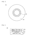
- a management zone 34e and a data zone 34f are formed as shown in Figure 2 . Compressed image data is written onto the data zone 34f.
- the management zone 34e is a region for managing as to how and what data is recorded in the data zone 34f, and written with a vacant capacity value of the data zone 34f in addition to compressed image data identifiers, data amounts and head addresses.
- storage areas 34g - 34i are formed as shown in Figure 3 .
- the storage area 34g stores number-of-times-of-writing data. This data is incremented each time predetermined bytes of the compressed image data is written to the data zone 34f of the disk 34c.
- the storage area 34h stores a duplication of the number-of-times-of-writing data of the storage area 34g. However, the duplication process is performed at a time that all the compressed image data secured in the compressed image area 24a of the SDRAM 24 has been written to the data zone 34f.
- the storage area 34i is to be written by a vacant capacity value of the data zone 34f.
- the vacant capacity value is to be written not only to the management zone 34e but also to the storage area 34i. Writing of a vacant capacity value to the storage area 34i is also made when all the compressed image data secured in the compressed image area 24a has been written to the data zone 34f.
- the CPU 36 concretely processes a flowchart shown in Figure 4 to Figure 6
- the controller 34a concretely processes a flowchart of Figure 7 and Figure 8 .
- both the CPU 36 and the controller 34a commence the process in response to turning on the power (turning on of the power switch 44).
- the CPU 36 determines, in step S1, a presence or absence of a through-image display process command.
- a through-image display process is made in step S3. That is, the TG 14 is instructed to perform thinning-out reading, and the signal processing circuit 20 and video encoder 26 is given a predetermined processing command. As a result, the though-image of a subject is displayed on the monitor 28.
- a disk startup command and number-of-times-of-writing-to-disk reading command is given to the controller 34a in the memory card 34.
- the controller 34a starts up the disk system 34b in response to the disk startup command.
- the controller 34a reads out number-of-times-of-writing data out of the storage areas 34g and 34h of the flash memory 34d in response to the number-of-time-of-writing-to-disk reading command and sends back the read number-of-times-of-writing data to the CPU 36.
- the CPU 36 compares between the two values of sent-back number-of-times-of-writing data in step S9. If the result of comparison shows coincidence, the CPU 36 in step S11 instructs the controller 34a to read a vacant capacity value out of the flash memory 34d. On the contrary, if the result of comparison shows non-coincidence, the CPU proceeds to step S15 to wait for sending back a startup completion signal from the controller 34a. When a startup completion signal is sent back, the CPU 36 in step S17 instructs the controller 34a to read a vacant capacity value out of the disk 34c.
- the memory card 34 is a removable, general-purpose recording medium and may be received in such a camera that the process as in this embodiment is not made. In such a case, there is no assurance that a correct vacant capacity value is always stored in the storage area 34i of the flash memory 34d. Consequently, in this embodiment, two of number-of-times-of-writing data are read out of the flash memory 34 to determine the truth/false of a vacant capacity value stored in the storage area depending upon coincidence/non-coincidence between them. If the vacant capacity value of the storage area 34d is correct, the controller 34a is instructed in step S11 to read out the vacant capacity value.
- step S15 If the vacant capacity value of the storage area 34d is incorrect, the controller 34a is instructed in step S15 to read a vacant capacity value out of the management zone 34e. However, because reading from the management zone 34e is impossible to perform unless the disk 34c is completely started up, the process of the step S15 is executed in response to the return of a startup completion signal.
- step S17 It is determined in step S17 whether a vacant capacity value is sent back from the controller 34a or not. If "YES”, in step S19 the number of recordable frames is calculated from the vacant capacity value. Specifically, the sent-back vacant capacity value is divided by a size of the compressed image data to determine the number of recordable frames.
- the CPU 36 subsequently indicates, on the display 48, the calculated number of recordable frames and, in step S23, determines whether the number of recordable frames is equal to or greater than "1" or not. If the number of recordable frames herein is "1" or greater, the process proceeds to step S25 while, if the number of recordable frames is "0", the process of step S23 is repeated. Consequently, when the number of recordable frames is "0", the operation of the shutter button 40 is always rendered invalid so that a through-image is kept in display on the monitor 28.
- the CPU 36 compares the maximum capacity value of the compressed image area 24a with the vacant capacity value of the disk 34c. If the vacant capacity value is greater than the maximum capacity value, the maximum capacity value in step S27 is written to the register 36a. If the vacant capacity value is smaller than the maximum capacity value, the vacant capacity value in step S29 is written to the register 36a.
- the register 36a is register to write an effective vacant capacity value of the compressed image area 24a. When the vacant capacity value of the disk 34c is smaller than the maximum capacity value of the compressed image area 24a, the capacity of the compressed image area 24a in a portion exceeding the vacant capacity of the disk 34c is made invalid.
- the compressed image data at the time the step S25 is processed has not been stored in the compressed image area 24a so that the vacant capacity value of the compressed image area 24a is equal to the maximum capacity value. Consequently, in the step S25, the maximum capacity value of the compressed image area 24a is compared with a vacant capacity value of the disk 34c.
- step S31 it is determined whether a record processing command has been given from the system controller 38 or not, i.e. whether the shutter button 40 has been pressed or not by the operator. If a record processing command has been given, in step S33 a picture-taking process is executed. Specifically, the TG 14 is instructed to perform all-pixel reading, the signal processing circuit 20 and encoder 26 is instructed to process signals, and the JPED CODEC 30 is instructed to perform a compression process. This outputs a high-resolution camera signal from the CCD imager 12, and the YUV data corresponding to the camera signal is produced by the signal processing circuit 20.
- the produced YUV data is converted into a composite image signal by the video encoder 26, and the same YUV data is compressed by the JPED CODEC 30.
- a freeze-image is displayed on the monitor 28 and the compressed image data is secured in the compressed image area 24a.
- the CPU 36 thereafter, in step S35, updates the vacant capacity of the compressed image area 24a. That is, the size of one-frame compressed image data is subtracted from the effective vacant capacity value stored in the register 36a.
- the picture-taking process ends when the compressed image data has been secured to the compressed image data 24a. Recording of the compressed image data to the memory card 34 is made in the later step.
- step S37 determines whether the disk 34c has started up or not and, in step S39, determines whether the vacant capacity is left sufficient in the compressed image 24a or not.
- the determination of the step S39 is made on the basis of a vacant capacity value of the register 36a. If the disk 34c has not yet been started up and the vacant capacity of the compressed image area 24a is insufficient, the CPU 36 repeats the process of the steps S37 and S39. On the other hand, if the disk 34c has not been completely started up but the vacant capacity of the compressed image area 24a is sufficient, the process returns to the step S31. Consequently, each time the shutter button 40 is operated, compressed image data is stored to the compressed image area 24a thereby decreasing the vacant capacity value of the register 36a.
- the determination of the step S37 is made based on a startup completion signal given from the controller 34a. That is, although “NO” is determined before startup completion signal has not been sent back, once a start up completion signal is sent back, “YES” is determined at all times from then on unless the power is not turned off.
- the determination result of "YES" in the step S37 represents that the rotation velocity of the disk 3 is stabilized thus acquiring a recordable state. Consequently, the CPU 36 advances to step S41 according to a determination result "YES” where it requests the memory control circuit 22 to read predetermined bytes of compressed image data. Also, in step S43, the read predetermined byte compressed image data is outputted, together with a write command, to the controller 34a.
- the controller 34a records the predetermined bytes of compressed image data to the disk 34c in response to the write command.
- the controller 34a also updates the number-of-times-of-writing stored in the storage area 34g of the flash memory 34d each time predetermined bytes have been recorded.
- the CPU 36 thereafter, in step S45, updates the vacant capacity value of the register 36a. That is, the current vacant capacity value is added with the predetermined bytes.
- step S47 it is determined whether the compressed image data stored in the compressed image area 24a have been all recorded or not. If "NO”, the process of the steps S41 - S47 is repeated. On the other hand, if "YES”, the process proceeds to step S49 where it instructs the controller 34a to update the vacant capacity value written on the disk 34c.
- the controller 34a updates the vacant capacity value of the management zone 34e in response to this instruction.
- the CPU 36 further, in step S51, instructs the controller 34a to duplicate the capacity value from the management zone 34e to the storage area 34h, and in step S53 instructs the controller 34a to duplicate the number-of-times-of-writing data from the storage area 34g to the storage area 34h.
- the controller 34a performs a duplication process of the vacant capacity value and number-of-times-of-writing data in response to these instructions. Completing the process of the step S53, the CPU 36 returns to the step S11.
- the step S49 is a process of taking into considering the versatility of the memory card 34. By this process, even if there is an error in the vacant capacity value of the flash memory 34, it is possible to detect a correct vacant capacity value by access to the management zone 34d.
- the step S51 is a process for reading a vacant capacity value swiftly upon turning the power in the next time. By writing a vacant capacity value to the flash memory 34d, a vacant capacity value of the disk 34c can be detected even before completing the startup of the disk 34c.
- the step S53 is a process for allowing determination as to truth/false of a vacant capacity value stored in the flash memory 34d.
- the controller 34d updates the number-of-times-of-writing data of the storage area 34g each time predetermined bytes of data has been recorded.
- the duplication process of a vacant capacity value to the storage area 34a and number-of-times-of-writing data to the storage area 34h is not performed unless duplication instructions of the steps S51 and S53 are provided.
- duplication process of a vacant capacity value and number-of-times-of-writing data is not made despite update is made to the number-of-times-of-writing data of the storage area 34g. Consequently, if there is a difference between the respective two of the number-of-times of writing stored in the storage areas 34g and 34h, the vacant capacity value stored in the storage area 34i represents an incorrect value. Accordingly, it is possible to determine truth/false of a vacant capacity value in the flash memory 34d according to the two of number-of-times of writing.
- step S5 When a disk startup command (generated in the step S5) is given from the CPU 36, the controller 34a in step S61 determines "YES” and, in step S63, starts up a spindle motor of the disk system 34b. Then, the process returns to the step S61.
- step S7 When a number-of-times-of-writing reading command (generated in the step S7) is given from the CPU 36, the controller 34a in step S65 determines "YES” and, in step S67, reads two of number-of-times-of-writing data including a duplication out of the storage areas 34g and 34h. The read number-of-times-of-writing data is sent back, in step S69, to the CPU 36, and the process returns to the step S61.
- step S71 determines "YES” and, in step S73, reads a vacant capacity value out of storage area 34i of the flash memory 34d.
- the read vacant capacity value is sent back, in step S75, to the CPU 36, and the process after sending back returns to the step S61.
- controller 34a in step S77 determines "YES” and, in step S79, reads a vacant capacity value out of the management zone 34e of the disk 34c.
- the read vacant capacity value is sent back, in step S81, to the CPU 36, and the process after sending back returns to the step S61.
- step S83 determines "YES" and, in step S85, fetches data (predetermined bytes of compressed image data). Subsequently, in step S87 the fetched data is written to the data area 34f and, in step S89, the number-of-times of writing stored in the storage area 34g is incremented. The number-of-times of writing stored in the storage area 34g is incremented each time predetermined bytes of compressed image data is written to the data zone 34f. Ending the process of the step S89, the process returns to the step S61.
- step S91 determines "YES" and, in step S93, detects a vacant capacity in the data zone. Then, in step S95, the vacant capacity value is written to the management zone 34e and the process returns to the step S61.
- step S97 determines "YES” and, in step S99, duplicates the vacant capacity value written in the management zone 34e to the storage area 34i of the flash memory 34d. Ending the duplication process, the process returns to the step S61.
- step S53 a number-of-times-of-writing duplication command
- step S103 duplicates the number-of-times-of-writing data. That is, the number-of-times-of-writing data in the storage area 34g is duplicated to the storage area 34h. Ending the duplication, the process returns to the step S61.
- step S105 determines whether the disk system 34b has been stabilized in operation, i.e., the rotation velocity of the spindle motor has become constant or not.
- the process directly returns to the step S61 while, if the rotation velocity has been stabilized, a startup completion signal in step S107 is outputted to the CPU 36 and then the process returns to the step S61.
- Data recording to the disk recording medium is impossible to perform before stabilizing the velocity of the spindle motor (disk). That is, where a disk is used as a recording medium, the time required for allowing recording after turning on the power is longer than the case using a semiconductor memory as a recording medium. Due to this, the operator, finding a best subject and turning on the power, is not allowed to immediately take a picture possibly missing a chance of shutter depressing.
- shutter button operation be made effective before entering a recordable state so that a photographic image can be temporarily held on the semiconductor memory within the camera. This however makes part of the photographic image not to be recorded when the vacant capacity of the disk-recording medium is less than the capacity of the semiconductor memory.
- the number of recordable frames cannot be determined unless a vacant capacity of the disk-recording medium is detected, requiring a time to indicate the number of recordable frames.
- the vacant capacity value of the disk 34c is written to the flash memory 34d each time the compressed image data stored in the compressed image data 24a has been recorded.
- the number of frames to be taken is limited based on the vacant capacity value read from the flash memory 34d. Specifically, the capacity of the compressed image area 24a is made invalid in a portion exceeding the vacant capacity of the disk 34c.
- the number of recordable frames is calculated based upon the read vacant capacity value to indicate a calculated number of recordable frames on the display 48. This makes it possible to operate the shutter button 42 and allow the number of recordable frames to be recognized even before the disk 34c becomes a recordable state.
- the vacant capacity value written in the flash memory 34d is not necessarily correct. Consequently, a marker (number-of-times-of-writing data) is written in addition to a vacant capacity value to the flash memory 34d thereby determining, based on the marker, whether the vacant capacity value is correct or not.
- the shutter button 42 is activated for operation after the disk 34d has completely started up.
- the disk system and the controller are provided within the memory card
- the memory card satisfactorily include at least a disk and flash memory. That is, the disk system and the controller may be provided in the digital camera.
- CMOS-type image sensor may be used in place thereof.
- the invention is applicable also to an audio recorder for recording the music data loaded by radio communication to a memory card through an internal memory.
- the data to be downloaded may be image data or letter data besides music data.
Description
- This invention relates generally to data recording apparatuses and, more particularly, to a data recording apparatus, which is applied for digital cameras, audio recorders or the like, for recording external data into a removable recording medium.
- In order to record data to such a recording medium as an optical disk, there is a need to first rotate the optical disk. A recordable state is first available after the rotation velocity of the disk has stabilized. Consequently, when using a disk as a recording medium, it takes longer in getting a recordable state after turning on a power as compared to the case using a semiconductor memory as a recording medium.
- Consequently, in the conventional digital camera using a disk recording medium, even if the power is turned on, the shutter button is not allowed to operate before the disk rotation velocity has stabilized. If herein a photographic image is temporarily stored to a semiconductor memory of the digital camera, shutter-button operation is possible even before stabilization in rotational velocity. However, recording to the disk must be assured for a photographic image once stored within the semiconductor memory through operation of the shutter button. In other words, in a state that a vacant capacity of the disk is less than a vacant capacity of the semiconductor memory, the shutter button should not be activated for operation. That is, whether to activate the shutter-button or not must be determined based upon a vacant capacity of the disk. In conclusion, the shutter button has been impossible to operate before disk rotation velocity has stabilized followed by reading a vacant capacity out of the disk.
- Meanwhile, in the prior art it takes long in indicating the number of recordable frames, because the number of recordable frames is to be first calculated after detecting a vacant capacity.
- Therefore, it is an primary object of the present invention to provide a data recording apparatus which can commence to fetch data even before a recordable state becomes available.
- Another object of the invention is to provide a data recording apparatus which can output information related to a vacant capacity immediately after turning on a power.
- According to the present invention, a data recording apparatus having a slot for receiving therein a removable recording medium including a first semiconductor memory and a disk, to record data fetched by a fetcher and temporarily stored in a second semiconductor memory to the disk, comprises: a vacant capacity value writer for writing a first vacant capacity value of the disk to the first semiconductor memory after the data have been recorded; a vacant capacity value reader for reading the first vacant capacity value out of the first semiconductor memory when turning on a power; and a restricter for restricting an amount of data to be fetched by the fetcher on the basis of the first vacant capacity value read out by the vacant capacity value reader.
- The data fetched by the fetcher, after temporarily stored in the second semiconductor memory, is recorded on a disk included within the recording medium received in the slot. Herein, the vacant capacity writer writes a first capacity value of the disk to the first semiconductor memory included in the recording medium after the data has been recorded. The vacant capacity value written in the first semiconductor memory is read out by the vacant capacity reader in response to turning on the power in the next time. The amount of data to be fetched by the fetcher is restricted based on the first vacant capacity value by the restricter. Consequently, data fetching can be commenced even before a recordable state becomes available.
- The restricter preferably includes a comparator to compare a second vacant value of the second semiconductor memory with the first vacant capacity value, and an invalidator for making invalid the second semiconductor memory in a portion exceeding the first vacant capacity value depending upon a result of comparison by the comparator.
- In a preferred embodiment of the invention, a starter starts up the disk after turning on the power. A determiner determines whether or not the disk has stabilized in rotation velocity. After the rotation velocity has stabilized, a recorder records the data stored on the second semiconductor memory to the disk.
- In another preferred embodiment of the invention, the fetcher includes a picture-taker to take a picture of a subject and a compressor to compress image data taken by the picture-taker. The second semiconductor memory stores image data compressed by the compressor. In a further preferred embodiment, a number-of-recordable-frames calculator calculates the number of recordable frames on the basis of the first vacant capacity value read out by the vacant capacity value reader. An indicator indicates the number of recordable frames.
- In still another embodiment of the invention, a marker writer writes a predetermined marker to the first semiconductor memory after the data have been recorded. A marker determiner determines whether or not the predetermined marker exists on the first semiconductor memory when the power is turned on. A disabler disables the fetcher for a predetermined time depending upon a result of determination by the marker determiner. Herein, the predetermined time is a time for which the disk comes into stabilization in rotation velocity.
- According to the present invention, a data recording apparatus having a slot for receiving therein a removable recording medium including a semiconductor memory and a disk, to record data fetched by a fetcher to the disk, comprises: a vacant capacity value writer to write a vacant capacity value of the disk to the semiconductor memory after the data have been recorded; a vacant capacity value reader to read the vacant capacity value out of the semiconductor memory when a power is turned on; and an outputter to output information related to the vacant capacity value read out by the reader.
- The data fetched by the fetcher is recorded to the disk included within the recording medium received in the slot. Completing the recording, a vacant capacity value is written to the semiconductor memory by the vacant capacity value writer. The vacant capacity value reader reads a vacant capacity value from the semiconductor memory in response to turning on the power in the next time. The outputter outputs information related to the read vacant capacity value. Consequently, it is possible yo output information related to a vacant capacity value immediately after turning on the power.
- In a preferred embodiment of the invention, the fetcher includes a picture-taker to take a picture of a subject, the outputter including a calculator to calculate the number of recordable frames on the basis of the vacant capacity value, and an indicator to indicate the number of recordable frames.
- The above described objects and other objects, features, aspects and advantages of the present invention will become more apparent from the following detailed description of the present invention when taken in conjunction with the accompanying drawings.
-
-
Figure 1 is a block diagram showing a configuration of one embodiment of the present invention; -
Figure 2 is an illustrative view showing a structure of a disk provided within a memory card; -
Figure 3 is an illustrative view showing a configuration of a flash memory provided within the memory card; -
Figure 4 is a flowchart showing part of operation of a CPU provided in the digital camera; -
Figure 5 is a flowchart showing another part of operation of the CPU provided in the digital camera; -
Figure 6 is a flowchart showing still another part of operation of the CPU provided in the digital camera; -
Figure 7 is a flowchart showing part of operation of a controller provided within the memory card; and -
Figure 8 is a flowchart showing another part of operation of the controller provided within the memory card. - Referring to
Figure 1 , adigital camera 10 of this embodiment includes apower switch 42. When an operator turns thepower switch 42 to an on state, a switch SW1 is interactively turned on and abattery 46 is put into connection to apower circuit 44. Thepower circuit 44 outputs a power voltage based on a battery voltage, thereby starting up thedigital camera 10 and thememory card 34 inserted in aslot 33. - Supplied with a power voltage, the
system controller 38 instructs aCPU 36 to perform a through-image display process. In response to the through-image display instruction, theCPU 36 instructs a timing generator (TG) 14 to perform thinning-out reading. TheTG 14 drives aCCD imager 12 by a thinning-out reading scheme. Due to this, a low-resolution camera signal (pixel signal) corresponding to a subject image illuminated to a light-receiving surface is outputted from theCCD imager 12. The output camera signal is subjected to well-known noise removal and level adjustment in a CDS/AGC circuit 16 and then converted into a digital signal by an A/D converter 18. - When instructed for a through-image display process, the
CPU 36 sends a process command to asignal processing circuit 20. Thesignal processing circuit 20 performs processes including color separation and YUV conversion on the camera data outputted from the A/D converter 18, and requests amemory control circuit 22 to write YUV data thus produced. In response to the write request, thememory control circuit 22 temporarily stores the YUV data in anSDRAM 24. TheCPU 36 sends a process command also to avideo encoder 26. Thevideo encoder 26 requests thememory control circuit 22 to read out YUV data and performs an encode process on the YUV data read out of theSDRAM 24. The YUV data is converted into a composite image signal, and the converted composite image signal is outputted onto amonitor 28. On themonitor 28, displayed is a real-time motion image (through-image) of the subject. - When the operator presses the
shutter button 40, thesystem controller 38 instructs theCPU 36 to perform a record process. Thereupon, theCPU 36 instructs theTG 14 to perform all-pixel reading. In response to this instruction, theTG 14 drives theCCD imager 12 by the all-pixel-reading scheme. As a result, a high-resolution camera signal (1-framed camera signal) corresponding to the subject image at a time of pressing theshutter button 40 is outputted from theCCD imager 12. - The
CPU 36, when instructed for a record process, also sends a process command to thesignal processing circuit 20 and thevideo encoder 26. Consequently, the camera signal outputted from theCCD imager 12 is processed in a manner similar to the above. That is, YUV data is produced based on the camera signal, and the produced YUV data is stored in theSDRAM 24. Thevideo encoder 26 reads YUV data out of theSDRAM 24 and converts the read YUV data into a composite image signal. As a result, a still image (freeze image) of the subject is displayed on themonitor 28. - The
CPU 36 also provides a compression command to aJPEG CODEC 30. In response to the compression command, theJPEG CODEC 30 requests thememory control circuit 22 to read out YUV data. In response to the read request, thememory control circuit 22 reads YUV data, i.e. subject still image data, out of theSDRAM 24 and provides it to theJPEG CODEC 30. The still image data is compressed according to the JPEG format. After producing compressed image data (JPEG data), theJPEG CODEC 30 provides the compressed image data, together with a write request, to thememory control circuit 22. Due to this, the compressed image data is also stored in theSDRAM 24. The compressed image data concretely is stored in acompressed image area 24a. - After the disk (optical disk) 34c arranged within the
memory card 34 has stabilized in operation, theCPU 36 requests thememory control circuit 22 to read out the compressed image data stored in thecompressed image area 24a. The compressed image data read out by thememory control circuit 22 is provided to acontroller 34a in thememory card 34 through an I/F circuit 32. Thecontroller 34a records the compressed image data to thedisk 34c by controlling adisk system 34b. After completing the recording, thesystem controller 38 instructs theCPU 36 to perform a through-image display process. As a result, a through-image process as mentioned above is again executed thereby displaying a through-image on themonitor 28. - Explaining in greater detail the
memory card 34 inserted in theslot 33, thedisk system 34b includes a spindle motor and an optical pickup (both not shown). On thedisk 34c, amanagement zone 34e and adata zone 34f are formed as shown inFigure 2 . Compressed image data is written onto thedata zone 34f. Themanagement zone 34e is a region for managing as to how and what data is recorded in thedata zone 34f, and written with a vacant capacity value of thedata zone 34f in addition to compressed image data identifiers, data amounts and head addresses. - On the
flash memory 34d,storage areas 34g - 34i are formed as shown inFigure 3 . Thestorage area 34g stores number-of-times-of-writing data. This data is incremented each time predetermined bytes of the compressed image data is written to thedata zone 34f of thedisk 34c. Thestorage area 34h stores a duplication of the number-of-times-of-writing data of thestorage area 34g. However, the duplication process is performed at a time that all the compressed image data secured in thecompressed image area 24a of theSDRAM 24 has been written to thedata zone 34f. Thestorage area 34i is to be written by a vacant capacity value of thedata zone 34f. That is, the vacant capacity value is to be written not only to themanagement zone 34e but also to thestorage area 34i. Writing of a vacant capacity value to thestorage area 34i is also made when all the compressed image data secured in thecompressed image area 24a has been written to thedata zone 34f. - In the camera mode, the
CPU 36 concretely processes a flowchart shown inFigure 4 to Figure 6 , while thecontroller 34a concretely processes a flowchart ofFigure 7 andFigure 8 . Incidentally, both theCPU 36 and thecontroller 34a commence the process in response to turning on the power (turning on of the power switch 44). - Referring first to
Figure 4 , theCPU 36 determines, in step S1, a presence or absence of a through-image display process command. When this process command is given, a through-image display process is made in step S3. That is, theTG 14 is instructed to perform thinning-out reading, and thesignal processing circuit 20 andvideo encoder 26 is given a predetermined processing command. As a result, the though-image of a subject is displayed on themonitor 28. - In the succeeding steps S5 and S7, a disk startup command and number-of-times-of-writing-to-disk reading command is given to the
controller 34a in thememory card 34. Thecontroller 34a starts up thedisk system 34b in response to the disk startup command. Also, thecontroller 34a reads out number-of-times-of-writing data out of thestorage areas flash memory 34d in response to the number-of-time-of-writing-to-disk reading command and sends back the read number-of-times-of-writing data to theCPU 36. - The
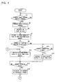
CPU 36 compares between the two values of sent-back number-of-times-of-writing data in step S9. If the result of comparison shows coincidence, theCPU 36 in step S11 instructs thecontroller 34a to read a vacant capacity value out of theflash memory 34d. On the contrary, if the result of comparison shows non-coincidence, the CPU proceeds to step S15 to wait for sending back a startup completion signal from thecontroller 34a. When a startup completion signal is sent back, theCPU 36 in step S17 instructs thecontroller 34a to read a vacant capacity value out of thedisk 34c. - The
memory card 34 is a removable, general-purpose recording medium and may be received in such a camera that the process as in this embodiment is not made. In such a case, there is no assurance that a correct vacant capacity value is always stored in thestorage area 34i of theflash memory 34d. Consequently, in this embodiment, two of number-of-times-of-writing data are read out of theflash memory 34 to determine the truth/false of a vacant capacity value stored in the storage area depending upon coincidence/non-coincidence between them. If the vacant capacity value of thestorage area 34d is correct, thecontroller 34a is instructed in step S11 to read out the vacant capacity value. If the vacant capacity value of thestorage area 34d is incorrect, thecontroller 34a is instructed in step S15 to read a vacant capacity value out of themanagement zone 34e. However, because reading from themanagement zone 34e is impossible to perform unless thedisk 34c is completely started up, the process of the step S15 is executed in response to the return of a startup completion signal. - Incidentally, described later is the reason that the vacant capacity value is incorrect when two of number-of-times-of-writing are not coincident.
- It is determined in step S17 whether a vacant capacity value is sent back from the
controller 34a or not. If "YES", in step S19 the number of recordable frames is calculated from the vacant capacity value. Specifically, the sent-back vacant capacity value is divided by a size of the compressed image data to determine the number of recordable frames. TheCPU 36 subsequently indicates, on thedisplay 48, the calculated number of recordable frames and, in step S23, determines whether the number of recordable frames is equal to or greater than "1" or not. If the number of recordable frames herein is "1" or greater, the process proceeds to step S25 while, if the number of recordable frames is "0", the process of step S23 is repeated. Consequently, when the number of recordable frames is "0", the operation of theshutter button 40 is always rendered invalid so that a through-image is kept in display on themonitor 28. - When advancing to step S25, the
CPU 36 compares the maximum capacity value of thecompressed image area 24a with the vacant capacity value of thedisk 34c. If the vacant capacity value is greater than the maximum capacity value, the maximum capacity value in step S27 is written to the register 36a. If the vacant capacity value is smaller than the maximum capacity value, the vacant capacity value in step S29 is written to the register 36a. The register 36a is register to write an effective vacant capacity value of thecompressed image area 24a. When the vacant capacity value of thedisk 34c is smaller than the maximum capacity value of thecompressed image area 24a, the capacity of thecompressed image area 24a in a portion exceeding the vacant capacity of thedisk 34c is made invalid. - Incidentally, the compressed image data at the time the step S25 is processed has not been stored in the
compressed image area 24a so that the vacant capacity value of thecompressed image area 24a is equal to the maximum capacity value. Consequently, in the step S25, the maximum capacity value of thecompressed image area 24a is compared with a vacant capacity value of thedisk 34c. - In step S31, it is determined whether a record processing command has been given from the
system controller 38 or not, i.e. whether theshutter button 40 has been pressed or not by the operator. If a record processing command has been given, in step S33 a picture-taking process is executed. Specifically, theTG 14 is instructed to perform all-pixel reading, thesignal processing circuit 20 andencoder 26 is instructed to process signals, and theJPED CODEC 30 is instructed to perform a compression process. This outputs a high-resolution camera signal from theCCD imager 12, and the YUV data corresponding to the camera signal is produced by thesignal processing circuit 20. Also, the produced YUV data is converted into a composite image signal by thevideo encoder 26, and the same YUV data is compressed by theJPED CODEC 30. As a result, a freeze-image is displayed on themonitor 28 and the compressed image data is secured in thecompressed image area 24a. TheCPU 36 thereafter, in step S35, updates the vacant capacity of thecompressed image area 24a. That is, the size of one-frame compressed image data is subtracted from the effective vacant capacity value stored in the register 36a. - Incidentally, the picture-taking process ends when the compressed image data has been secured to the
compressed image data 24a. Recording of the compressed image data to thememory card 34 is made in the later step. - The
CPU 34 subsequently, in step S37, determines whether thedisk 34c has started up or not and, in step S39, determines whether the vacant capacity is left sufficient in thecompressed image 24a or not. The determination of the step S39 is made on the basis of a vacant capacity value of the register 36a. If thedisk 34c has not yet been started up and the vacant capacity of thecompressed image area 24a is insufficient, theCPU 36 repeats the process of the steps S37 and S39. On the other hand, if thedisk 34c has not been completely started up but the vacant capacity of thecompressed image area 24a is sufficient, the process returns to the step S31. Consequently, each time theshutter button 40 is operated, compressed image data is stored to thecompressed image area 24a thereby decreasing the vacant capacity value of the register 36a. - Incidentally, the determination of the step S37 is made based on a startup completion signal given from the
controller 34a. That is, although "NO" is determined before startup completion signal has not been sent back, once a start up completion signal is sent back, "YES" is determined at all times from then on unless the power is not turned off. - The determination result of "YES" in the step S37 represents that the rotation velocity of the
disk 3 is stabilized thus acquiring a recordable state. Consequently, theCPU 36 advances to step S41 according to a determination result "YES" where it requests thememory control circuit 22 to read predetermined bytes of compressed image data. Also, in step S43, the read predetermined byte compressed image data is outputted, together with a write command, to thecontroller 34a. Thecontroller 34a records the predetermined bytes of compressed image data to thedisk 34c in response to the write command. Thecontroller 34a also updates the number-of-times-of-writing stored in thestorage area 34g of theflash memory 34d each time predetermined bytes have been recorded. TheCPU 36 thereafter, in step S45, updates the vacant capacity value of the register 36a. That is, the current vacant capacity value is added with the predetermined bytes. - In step S47, it is determined whether the compressed image data stored in the
compressed image area 24a have been all recorded or not. If "NO", the process of the steps S41 - S47 is repeated. On the other hand, if "YES", the process proceeds to step S49 where it instructs thecontroller 34a to update the vacant capacity value written on thedisk 34c. Thecontroller 34a updates the vacant capacity value of themanagement zone 34e in response to this instruction. TheCPU 36 further, in step S51, instructs thecontroller 34a to duplicate the capacity value from themanagement zone 34e to thestorage area 34h, and in step S53 instructs thecontroller 34a to duplicate the number-of-times-of-writing data from thestorage area 34g to thestorage area 34h. Thecontroller 34a performs a duplication process of the vacant capacity value and number-of-times-of-writing data in response to these instructions. Completing the process of the step S53, theCPU 36 returns to the step S11. - The step S49 is a process of taking into considering the versatility of the
memory card 34. By this process, even if there is an error in the vacant capacity value of theflash memory 34, it is possible to detect a correct vacant capacity value by access to themanagement zone 34d. The step S51 is a process for reading a vacant capacity value swiftly upon turning the power in the next time. By writing a vacant capacity value to theflash memory 34d, a vacant capacity value of thedisk 34c can be detected even before completing the startup of thedisk 34c. - The step S53 is a process for allowing determination as to truth/false of a vacant capacity value stored in the
flash memory 34d. Thecontroller 34d updates the number-of-times-of-writing data of thestorage area 34g each time predetermined bytes of data has been recorded. However, the duplication process of a vacant capacity value to thestorage area 34a and number-of-times-of-writing data to thestorage area 34h is not performed unless duplication instructions of the steps S51 and S53 are provided. That is, where thememory card 34 is attached to such a camera that the process as in this embodiment is not performed, duplication process of a vacant capacity value and number-of-times-of-writing data is not made despite update is made to the number-of-times-of-writing data of thestorage area 34g. Consequently, if there is a difference between the respective two of the number-of-times of writing stored in thestorage areas storage area 34i represents an incorrect value. Accordingly, it is possible to determine truth/false of a vacant capacity value in theflash memory 34d according to the two of number-of-times of writing. - Subsequently, the process by the
controller 34a will be explained with reference toFigure 7 andFigure 8 . When a disk startup command (generated in the step S5) is given from theCPU 36, thecontroller 34a in step S61 determines "YES" and, in step S63, starts up a spindle motor of thedisk system 34b. Then, the process returns to the step S61. When a number-of-times-of-writing reading command (generated in the step S7) is given from theCPU 36, thecontroller 34a in step S65 determines "YES" and, in step S67, reads two of number-of-times-of-writing data including a duplication out of thestorage areas CPU 36, and the process returns to the step S61. - Where a vacant-capacity-value reading command (generated in the step S11) is given from the
CPU 36, thecontroller 34a in step S71 determines "YES" and, in step S73, reads a vacant capacity value out ofstorage area 34i of theflash memory 34d. The read vacant capacity value is sent back, in step S75, to theCPU 36, and the process after sending back returns to the step S61. Where a vacant-capacity-value reading command (generated in the step S15) is given from theCPU 36,controller 34a in step S77 determines "YES" and, in step S79, reads a vacant capacity value out of themanagement zone 34e of thedisk 34c. The read vacant capacity value is sent back, in step S81, to theCPU 36, and the process after sending back returns to the step S61. - Where a data write command (generated in step S43) is given from the
CPU 36, thecontroller 34a in step S83 determines "YES" and, in step S85, fetches data (predetermined bytes of compressed image data). Subsequently, in step S87 the fetched data is written to thedata area 34f and, in step S89, the number-of-times of writing stored in thestorage area 34g is incremented. The number-of-times of writing stored in thestorage area 34g is incremented each time predetermined bytes of compressed image data is written to thedata zone 34f. Ending the process of the step S89, the process returns to the step S61. Where a vacant-capacity-value update command (generated in the step S49) is given from theCPU 36, thecontroller 34a in step S91 determines "YES" and, in step S93, detects a vacant capacity in the data zone. Then, in step S95, the vacant capacity value is written to themanagement zone 34e and the process returns to the step S61. - Where a vacant-capacity-value duplication command (generated in step S51) from the
CPU 36, thecontroller 34a in step S97 determines "YES" and, in step S99, duplicates the vacant capacity value written in themanagement zone 34e to thestorage area 34i of theflash memory 34d. Ending the duplication process, the process returns to the step S61. Where a number-of-times-of-writing duplication command (generated in step S53) is given from theCPU 36, thecontroller 34a in step S101 determines "YES" and, in step S103, duplicates the number-of-times-of-writing data. That is, the number-of-times-of-writing data in thestorage area 34g is duplicated to thestorage area 34h. Ending the duplication, the process returns to the step S61. - Where any of the above commands is not given, the
controller 34a proceeds to step S105 to determine whether thedisk system 34b has been stabilized in operation, i.e., the rotation velocity of the spindle motor has become constant or not. Here, if the rotational velocity is varying, the process directly returns to the step S61 while, if the rotation velocity has been stabilized, a startup completion signal in step S107 is outputted to theCPU 36 and then the process returns to the step S61. - Data recording to the disk recording medium is impossible to perform before stabilizing the velocity of the spindle motor (disk). That is, where a disk is used as a recording medium, the time required for allowing recording after turning on the power is longer than the case using a semiconductor memory as a recording medium. Due to this, the operator, finding a best subject and turning on the power, is not allowed to immediately take a picture possibly missing a chance of shutter depressing.
- Herein, it can be considered that shutter button operation be made effective before entering a recordable state so that a photographic image can be temporarily held on the semiconductor memory within the camera. This however makes part of the photographic image not to be recorded when the vacant capacity of the disk-recording medium is less than the capacity of the semiconductor memory. In conclusion, in order for assuring to record a photographic image, there is a need of detecting a vacant capacity of the disk-recording medium before activating the shutter button. Furthermore, the number of recordable frames cannot be determined unless a vacant capacity of the disk-recording medium is detected, requiring a time to indicate the number of recordable frames.
- Consequently, in this embodiment, the vacant capacity value of the
disk 34c is written to theflash memory 34d each time the compressed image data stored in thecompressed image data 24a has been recorded. Upon turning the power on in the next time, the number of frames to be taken is limited based on the vacant capacity value read from theflash memory 34d. Specifically, the capacity of thecompressed image area 24a is made invalid in a portion exceeding the vacant capacity of thedisk 34c. Also, the number of recordable frames is calculated based upon the read vacant capacity value to indicate a calculated number of recordable frames on thedisplay 48. This makes it possible to operate theshutter button 42 and allow the number of recordable frames to be recognized even before thedisk 34c becomes a recordable state. - Meanwhile, where the
memory card 34 of this embodiment is employed for another digital camera, the vacant capacity value written in theflash memory 34d is not necessarily correct. Consequently, a marker (number-of-times-of-writing data) is written in addition to a vacant capacity value to theflash memory 34d thereby determining, based on the marker, whether the vacant capacity value is correct or not. Here, if the vacant capacity value is incorrect, theshutter button 42 is activated for operation after thedisk 34d has completely started up. - Incidentally, in this embodiment, although the disk system and the controller are provided within the memory card, the memory card satisfactorily include at least a disk and flash memory. That is, the disk system and the controller may be provided in the digital camera.
- Also, in this embodiment, although the image sensor of the CCD type is used, a CMOS-type image sensor may be used in place thereof.
- Furthermore, this embodiment explained using the digital camera, the invention is applicable also to an audio recorder for recording the music data loaded by radio communication to a memory card through an internal memory. Also, the data to be downloaded may be image data or letter data besides music data.
- Although the present invention has been described and illustrated in detail, it is clearly understood that the same is by way of illustration and example only and is not to be taken by way of limitation, the scope of the present invention being limited only by the terms of the appended claims.
Claims (7)
- A data recording apparatus (10) comprising: a slot (33) for receiving therein a removable recording medium (34) including a semiconductor memory (34d) and a disk (34c); a recording means (S41, S43) for recording data fetched by a fetching means (22, 30) to said disk; and a first vacant capacity value writing means (S49) for writing a vacant capacity value of said disk to said disk after the data have been recorded,
characterized in that said data recording apparatus further comprises:a second vacant capacity value writing means (S51) for writing the vacant capacity value of said disk to said semiconductor memory after the data have been recorded;a marker writing means (S53) for writing a marker to said semiconductor memory after the data have been recorded;a determining means (S9) for determining whether or not the marker stored in said semiconductor memory satisfies a predetermined condition in response to a power being turned on;a first vacant capacity value reading means (S11) for reading the vacant capacity value from said semiconductor memory when a determination result of said determining means is affirmative;a second vacant capacity value reading means (S15) for reading the vacant capacity value from said disk when the determination result of said determining means is negative; andan outputting means (S19, S21) for outputting information in association with the vacant capacity value thus read. - A data recording apparatus (10) according to claim 1, further comprising:a restricting means (S25, S27, S29) for restricting a data amount to be fetched by said fetching means based on the vacant capacity value output by said outputting means.
- A data recording apparatus according to claim 2, wherein said restricting means includes an invalidating means (S29) for making invalid said second semiconductor memory in a portion exceeding a vacant capacity of said disk.
- A data recording apparatus according to claim 2, further comprising a starting means (S5) for starting up said disk after turning on the power, wherein said recording means carries out a recording process after a rotation velocity of said disk has stabilized.
- A data recording apparatus according to claim 2, wherein said fetching means includes a compressing means (30) for compressing image data of a captured object scene, and said second semiconductor memory stores compressed image data created by said compressing means.
- A data recording apparatus according to claim 2, wherein said recording medium includes an information writing means (33, S89) for writing to a first area (34g) of said first semiconductor memory first value information which indicates a number of times of data recording, and said marker writing means writes to a second area (34h) of said first semiconductor memory second value information which satisfies the predetermined condition between the first value information as the marker.
- A data recording apparatus according to claim 1, wherein the data fetched by said fetching means is still image data, and said outputting means includes a calculating means (S19) for calculating the number of recordable images based on the vacant capacity value, and a displaying means (21) for displaying the number of recordable images calculated by said calculating means.
Applications Claiming Priority (2)
| Application Number | Priority Date | Filing Date | Title |
|---|---|---|---|
| JP35448399A JP3510829B2 (en) | 1999-12-14 | 1999-12-14 | Data recording device |
| JP35448399 | 1999-12-14 |
Publications (3)
| Publication Number | Publication Date |
|---|---|
| EP1109403A2 EP1109403A2 (en) | 2001-06-20 |
| EP1109403A3 EP1109403A3 (en) | 2004-12-01 |
| EP1109403B1 true EP1109403B1 (en) | 2008-05-28 |
Family
ID=18437879
Family Applications (1)
| Application Number | Title | Priority Date | Filing Date |
|---|---|---|---|
| EP00127153A Expired - Lifetime EP1109403B1 (en) | 1999-12-14 | 2000-12-12 | Data recording apparatus |
Country Status (7)
| Country | Link |
|---|---|
| US (1) | US6788341B2 (en) |
| EP (1) | EP1109403B1 (en) |
| JP (1) | JP3510829B2 (en) |
| KR (1) | KR100689179B1 (en) |
| CN (1) | CN1184628C (en) |
| DE (1) | DE60039021D1 (en) |
| ID (1) | ID28608A (en) |
Families Citing this family (14)
| Publication number | Priority date | Publication date | Assignee | Title |
|---|---|---|---|---|
| JP4432160B2 (en) * | 1999-09-22 | 2010-03-17 | 株式会社ニコン | Electronic camera |
| JP3593977B2 (en) * | 2000-12-25 | 2004-11-24 | 株式会社日立製作所 | Image reading device |
| JP2002247517A (en) * | 2001-02-14 | 2002-08-30 | Sanyo Electric Co Ltd | Digital camera |
| JP2003125256A (en) * | 2001-10-18 | 2003-04-25 | Fuji Photo Film Co Ltd | Imaging apparatus and replacement unit |
| AU2003202493A1 (en) | 2002-01-11 | 2003-07-30 | Nikon Corporation | Digital camera |
| US20050151858A1 (en) * | 2002-02-18 | 2005-07-14 | Nikon Corporation | Digital camera |
| JP2003303472A (en) * | 2002-04-04 | 2003-10-24 | Hitachi Ltd | Information recording device and method for recording information |
| JP3794345B2 (en) * | 2002-04-25 | 2006-07-05 | 株式会社日立製作所 | Information recording apparatus and information recording method |
| JP2005175983A (en) * | 2003-12-12 | 2005-06-30 | Canon Inc | Image recording apparatus and recording medium |
| JP4001135B2 (en) * | 2004-08-18 | 2007-10-31 | ソニー株式会社 | Video signal processing device |
| JP4432870B2 (en) * | 2005-10-04 | 2010-03-17 | ソニー株式会社 | RECORDING DEVICE, RECORDING MEDIUM MANAGEMENT METHOD, RECORDING MEDIUM MANAGEMENT METHOD PROGRAM, AND RECORDING MEDIUM MANAGEMENT METHOD PROGRAM |
| JP4444912B2 (en) * | 2005-11-17 | 2010-03-31 | キヤノン株式会社 | Video camera |
| JP2007184039A (en) * | 2006-01-06 | 2007-07-19 | Canon Inc | Information recorder |
| DK176211B1 (en) * | 2006-03-24 | 2007-02-05 | Smidth As F L | Cyclone separator e.g. for use in cement manufacture, has annular disc in supporting element arranged between cyclone housing and discharge duct, forming clearance between housing and duct and disc |
Family Cites Families (20)
| Publication number | Priority date | Publication date | Assignee | Title |
|---|---|---|---|---|
| JPS5450255A (en) * | 1977-09-28 | 1979-04-20 | Matsushita Electric Ind Co Ltd | Delay line equipment |
| US5170262A (en) * | 1985-09-13 | 1992-12-08 | Canon Kabushiki Kaisha | Electronic camera |
| US4723181A (en) * | 1986-09-24 | 1988-02-02 | Eastman Kodak Company | Tape memory with integral disk index on reel |
| EP0265167B1 (en) * | 1986-10-15 | 1997-01-02 | Pioneer Electronic Corporation | Disk player with disk magazine |
| EP0266101B1 (en) * | 1986-10-16 | 1991-05-15 | Hitachi Maxell Ltd. | Composite memory device |
| JPH03136570A (en) * | 1989-10-23 | 1991-06-11 | Ricoh Co Ltd | Facsimile mail equipment |
| JPH04181583A (en) | 1990-11-15 | 1992-06-29 | Hitachi Ltd | Recording medium and recording management system and data processing device |
| JPH05276471A (en) * | 1992-03-25 | 1993-10-22 | Asahi Optical Co Ltd | Empty track retrieving device for electronic still camera |
| JPH0666539A (en) * | 1992-08-19 | 1994-03-08 | Shinko Electric Ind Co Ltd | Image processor |
| JP3173290B2 (en) * | 1994-07-15 | 2001-06-04 | 三菱マテリアル株式会社 | Scallop ear hanging machine and scallop ear hanging method |
| GB2286267A (en) * | 1994-02-03 | 1995-08-09 | Ibm | Energy-saving cache control system |
| JPH0879681A (en) * | 1994-09-08 | 1996-03-22 | Asahi Optical Co Ltd | Electronic still camera |
| MY116522A (en) * | 1995-05-31 | 2004-02-28 | Sony Corp | Data recording/reproducing apparatus, method thereof, and data recording medium |
| JPH1051722A (en) * | 1996-08-05 | 1998-02-20 | Hitachi Ltd | Camera where disk is set to be recording medium |
| JPH10145717A (en) | 1996-11-05 | 1998-05-29 | Canon Inc | Electronic camera |
| JPH10149650A (en) * | 1996-11-18 | 1998-06-02 | Hitachi Ltd | Disk cartridge equipped with semiconductor ic and information recording/reproducing device using the same |
| JPH11331530A (en) * | 1998-05-13 | 1999-11-30 | Canon Inc | Peripheral device and its storage control method and storage medium |
| CN100502137C (en) * | 2004-11-19 | 2009-06-17 | 松下电器产业株式会社 | Nonaqueous electrolyte secondary battery |
| KR100666539B1 (en) * | 2005-09-21 | 2007-01-09 | 현대자동차주식회사 | Structure for outside mirror the base in automobile |
| JP5450255B2 (en) * | 2010-05-25 | 2014-03-26 | ニチコン株式会社 | Switching power supply |
-
1999
- 1999-12-14 JP JP35448399A patent/JP3510829B2/en not_active Expired - Fee Related
-
2000
- 2000-12-12 ID IDP20001068D patent/ID28608A/en unknown
- 2000-12-12 EP EP00127153A patent/EP1109403B1/en not_active Expired - Lifetime
- 2000-12-12 DE DE60039021T patent/DE60039021D1/en not_active Expired - Lifetime
- 2000-12-13 US US09/734,728 patent/US6788341B2/en not_active Expired - Fee Related
- 2000-12-13 KR KR1020000075825A patent/KR100689179B1/en not_active IP Right Cessation
- 2000-12-14 CN CNB001282654A patent/CN1184628C/en not_active Expired - Fee Related
Also Published As
| Publication number | Publication date |
|---|---|
| KR20010070300A (en) | 2001-07-25 |
| JP3510829B2 (en) | 2004-03-29 |
| DE60039021D1 (en) | 2008-07-10 |
| EP1109403A2 (en) | 2001-06-20 |
| CN1302062A (en) | 2001-07-04 |
| JP2001175512A (en) | 2001-06-29 |
| US6788341B2 (en) | 2004-09-07 |
| CN1184628C (en) | 2005-01-12 |
| US20010005223A1 (en) | 2001-06-28 |
| EP1109403A3 (en) | 2004-12-01 |
| ID28608A (en) | 2001-06-14 |
| KR100689179B1 (en) | 2007-03-08 |
Similar Documents
| Publication | Publication Date | Title |
|---|---|---|
| EP1109403B1 (en) | Data recording apparatus | |
| US5956084A (en) | Electronic still-video camera, and playback apparatus therefor being capable of storing image data when the storage capacity of a memory card is exceeded | |
| US6978086B2 (en) | Imaging apparatus | |
| EP0996286B1 (en) | Electronic camera | |
| US6603509B1 (en) | Digital camera controllable by a program | |
| US7684679B2 (en) | Image recording apparatus | |
| JPH10248046A (en) | Electronic image pickup deivce, electronic camera system and recording medium | |
| JP2003157668A (en) | Information recorder | |
| EP1189426A2 (en) | Disk Apparatus | |
| US20040022516A1 (en) | Image recording system and image recording reproducing apparatus | |
| JP3147798B2 (en) | Image input device | |
| JPH11187350A (en) | Image pickup recorder and its control method | |
| JP2001054100A (en) | Monitoring device | |
| JP2002369184A (en) | Image processor, image pickup device, control method of image processor, control method of image pickup device, and recording medium | |
| KR100486483B1 (en) | Digital video recorder using universal serial bus memory for vehicle mounting and video recording method using the recorder | |
| JP2001309222A (en) | Portable imaging apparatus and its operation control method | |
| JP2002199322A (en) | Imaging system, imaging unit, image processor and signal processing method | |
| US8482811B2 (en) | Recording apparatus | |
| JP2001111939A (en) | Image pickup device, image pickup method, image pickup system and computer-readable recording medium | |
| JP4499901B2 (en) | Electronic camera | |
| JP2003209787A (en) | Information processor, imaging apparatus, information processing system, information storing method, storage medium, and program | |
| JP4599008B2 (en) | IMAGING DEVICE AND IMAGING DEVICE CONTROL METHOD | |
| JP2003259289A (en) | Image pickup device and data display method | |
| JPH07222097A (en) | Electronic still camera | |
| JP2004213402A (en) | Video and voice signal recording device |
Legal Events
| Date | Code | Title | Description |
|---|---|---|---|
| PUAI | Public reference made under article 153(3) epc to a published international application that has entered the european phase |
Free format text: ORIGINAL CODE: 0009012 |
|
| AK | Designated contracting states |
Kind code of ref document: A2 Designated state(s): AT BE CH CY DE DK ES FI FR GB GR IE IT LI LU MC NL PT SE TR |
|
| AX | Request for extension of the european patent |
Free format text: AL;LT;LV;MK;RO;SI |
|
| PUAL | Search report despatched |
Free format text: ORIGINAL CODE: 0009013 |
|
| AK | Designated contracting states |
Kind code of ref document: A3 Designated state(s): AT BE CH CY DE DK ES FI FR GB GR IE IT LI LU MC NL PT SE TR |
|
| AX | Request for extension of the european patent |
Extension state: AL LT LV MK RO SI |
|
| RIC1 | Information provided on ipc code assigned before grant |
Ipc: 7H 04N 5/77 A Ipc: 7H 04N 1/21 B Ipc: 7H 04N 5/85 B |
|
| 17P | Request for examination filed |
Effective date: 20041210 |
|
| AKX | Designation fees paid |
Designated state(s): DE FR GB |
|
| GRAP | Despatch of communication of intention to grant a patent |
Free format text: ORIGINAL CODE: EPIDOSNIGR1 |
|
| GRAS | Grant fee paid |
Free format text: ORIGINAL CODE: EPIDOSNIGR3 |
|
| GRAA | (expected) grant |
Free format text: ORIGINAL CODE: 0009210 |
|
| AK | Designated contracting states |
Kind code of ref document: B1 Designated state(s): DE FR GB |
|
| REG | Reference to a national code |
Ref country code: GB Ref legal event code: FG4D |
|
| REF | Corresponds to: |
Ref document number: 60039021 Country of ref document: DE Date of ref document: 20080710 Kind code of ref document: P |
|
| PLBE | No opposition filed within time limit |
Free format text: ORIGINAL CODE: 0009261 |
|
| STAA | Information on the status of an ep patent application or granted ep patent |
Free format text: STATUS: NO OPPOSITION FILED WITHIN TIME LIMIT |
|
| 26N | No opposition filed |
Effective date: 20090303 |
|
| REG | Reference to a national code |
Ref country code: FR Ref legal event code: ST Effective date: 20090831 |
|
| PG25 | Lapsed in a contracting state [announced via postgrant information from national office to epo] |
Ref country code: FR Free format text: LAPSE BECAUSE OF NON-PAYMENT OF DUE FEES Effective date: 20081231 |
|
| PGFP | Annual fee paid to national office [announced via postgrant information from national office to epo] |
Ref country code: DE Payment date: 20121205 Year of fee payment: 13 |
|
| PGFP | Annual fee paid to national office [announced via postgrant information from national office to epo] |
Ref country code: GB Payment date: 20121212 Year of fee payment: 13 |
|
| REG | Reference to a national code |
Ref country code: DE Ref legal event code: R119 Ref document number: 60039021 Country of ref document: DE |
|
| GBPC | Gb: european patent ceased through non-payment of renewal fee |
Effective date: 20131212 |
|
| REG | Reference to a national code |
Ref country code: DE Ref legal event code: R119 Ref document number: 60039021 Country of ref document: DE Effective date: 20140701 |
|
| PG25 | Lapsed in a contracting state [announced via postgrant information from national office to epo] |
Ref country code: DE Free format text: LAPSE BECAUSE OF NON-PAYMENT OF DUE FEES Effective date: 20140701 |
|
| PG25 | Lapsed in a contracting state [announced via postgrant information from national office to epo] |
Ref country code: GB Free format text: LAPSE BECAUSE OF NON-PAYMENT OF DUE FEES Effective date: 20131212 |