EP1109082B1 - Generator in particular for timepiece - Google Patents
Generator in particular for timepiece Download PDFInfo
- Publication number
- EP1109082B1 EP1109082B1 EP99124387A EP99124387A EP1109082B1 EP 1109082 B1 EP1109082 B1 EP 1109082B1 EP 99124387 A EP99124387 A EP 99124387A EP 99124387 A EP99124387 A EP 99124387A EP 1109082 B1 EP1109082 B1 EP 1109082B1
- Authority
- EP
- European Patent Office
- Prior art keywords
- coils
- rotor
- generator
- parts
- flexible film
- Prior art date
- Legal status (The legal status is an assumption and is not a legal conclusion. Google has not performed a legal analysis and makes no representation as to the accuracy of the status listed.)
- Expired - Lifetime
Links
Images


Classifications
-
- G—PHYSICS
- G04—HOROLOGY
- G04C—ELECTROMECHANICAL CLOCKS OR WATCHES
- G04C10/00—Arrangements of electric power supplies in time pieces
-
- H—ELECTRICITY
- H02—GENERATION; CONVERSION OR DISTRIBUTION OF ELECTRIC POWER
- H02K—DYNAMO-ELECTRIC MACHINES
- H02K3/00—Details of windings
Definitions
- the present invention relates to a generator of the watchmaker type and to a watch movement equipped with such a generator, in particular for a wristwatch.
- batteries or accumulators are for all applications, and in particular for a watch, a factor limiting the characteristics of the device. Indeed, the change or recharge of these batteries or accumulators affects the availability and reliability of the watch.
- the traditional mechanical watch has a certain advantage in the watchmaking technique: such a watch is permanently available.
- the energy recharge - the latter being purely mechanical - is done simply by reassembling the mechanism of the watch.
- This type of watch uses a manual or automatic winding device generally coupled to a control device named in the use "Swiss lever escapement”. This control device makes it difficult to obtain high accuracy. This system is also relatively expensive.
- the other big family concerns the classic quartz watch.
- a battery simultaneously powers an electric motor and a device for regulating the running of this motor.
- the rotation of the motor is controlled by a nominal frequency provided by a quartz. This makes it possible to have a good precision for the indication of the time.
- this device is relatively noisy because the advance of the seconds wheel is jerky and the battery must be changed periodically.
- mechanical energy storage has been associated with quartz regulation, supplied with electrical energy by a generator driven by a mechanical part coupled to an energy storage spring.
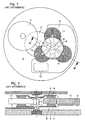
- FIG. 1 The arrangement of the generator according to this prior art is illustrated in the figure 1 attached, showing a top view of a watch movement partially mounted, and in the figure 2 attached, which is a cross-section of the figure 1 .
- This generator comprises a rotor having two flanges 8 arranged on either side of three flat coils 11 forming the stator and shifted by 120 ° relative to one another relative to the axis of the rotor, in the same plane orthogonal to this one.
- a printed circuit 6 is fixed to the plate 4 and serves as a support for the coils 11.
- the supply of the electronic circuit 10, with low power consumption, is provided by an electric generator - consisting of the rotor shaft assembly 5, flanges 8, magnets 9 and coils 11 - driven via the kinematic link 3 by the device 2.
- the mechanical energy stored in the barrel 2 therefore drives the rotor.
- the passage of the magnets 9 near the coils 11 generates a substantially sinusoidal induced voltage across these coils 11.
- the figure 3 attached schematically highlights the fact that the assembly of the monobloc rotor - consisting of parts 5, 8 and 9 - is currently by lateral insertion of the shaft 5 between two fixed coils 11.
- the rotor, monoblock can not be inserted vertically since the three coils 11 are fixed and the flanges 8 located on either side of these coils must partially cover them.
- the coils 11 have a spacing, referenced DMin at the figure 3 attached, at least as wide as the shaft 5 of the rotor, having a diameter D in the middle, to allow the introduction of this shaft laterally to its final location in the center of the three coils.
- the invention aims to remedy these drawbacks. It relates for this purpose to a generator of the watchmaker type comprising on the one hand a rotor comprising two flanges carried by a shaft, this shaft and these flanges being rotationally fixed in running order, magnets being fixed to each flange in number pair - two consecutive magnets or vis-à-vis being of opposite polarity - and further comprising a stator formed of at least three coils of axes parallel to that of the rotor and arranged on a support, these coils being arranged between the two flanges provided with magnets and sparing between them a sufficient central space for said rotor shaft.
- This generator is characterized in that the coil support is formed of at least two parts arranged to be assembled with the rotor independently of one another and each carrying at least one coil, and in that it is provided electrical connection means between these at least two parts, the distance separating any two adjacent coils being less than the diameter D of the rotor shaft.
- the generator of the watchmaker type is characterized in that the coil carrier has at least two rigid or rigidified parts each carrying at least one coil and a deformable part physically connecting these two rigid parts, this deformable portion being arranged to be deformed elastically during assembly of the rotor with the stator to allow the lateral passage of the shaft of this rotor between two coils, the distance separating any two adjacent coils being less than the diameter D of the rotor shaft.
- the characteristics of the invention according to the first or second embodiment mentioned above it is possible to optimally use the coupling space between the rotor magnets and the stator coils.
- the diameter of the rotor shaft is no longer a parameter limiting the dimensions of the stator coils. As a result, the efficiency of the generator and / or the size of the stator are improved.
- the figure 4 shows the arrangement of the rotor whose upper flange 8 and the magnets 9 they carry are shown in phantom.
- the rotor shaft 5 has at its center a diameter D which is greater than the distance separating any two adjacent coils.
- the coils 11a, 11b and 11c define a central space 13 where is arranged the shaft 5 of the rotor.
- the overlap between the coils 11a, 11b and 11c and the flanges 8 of the rotor is greater than in the case of the prior art shown in FIG. figure 3 .
- the design of the generator according to the invention makes it possible to increase the magnet-coil coupling of the generator and / or to minimize the size of the stator.
- the stator of the generator is formed of a support 6 comprising two separate plates 21 and 22 and three coils 11a, 11b and 11c.
- the plate 22 carries the coils 11b and 11c.
- the coil 11a can be introduced between the flanges 8 of the rotor independently of the introduction of the coils 11b and 11c.
- the plate 21 is fixed to the body 4 of a watch movement with two screws 12 and 12a.
- the plate 22 is fixed to this body 4 by means of two screws 12 and 12b.
- the plates 21 and 22 are connected by a bridge 30 fixed to the body 4 by means of the screws 12a and 12b.
- This bridge 30 serves to establish an electrical connection between two electrical tracks 25 and 26 represented partially at the figure 5 .
- the bridge 30 thus has two tracks 31 and 32 on its face facing the plates 21 and 22.
- the ends of the tracks 31 and 32 have ends in a circular arc arranged around the holes 33 and 34 respectively provided for the passage of the screws 12a and 12b.
- the tracks 31 and 32 can be arranged differently. It is sufficient that these tracks make it possible to establish an electrical connection between the tracks 25 and 26 provided on the one hand on the plate 21 and on the other hand on the plate 22.
- the stator 6 differs from the previous mode in that it is formed of two plates 41 and 42 partially superimposed on one another after assembly of the generator. In the region of superposition 44 between the plates 41 and 42 are arranged contact pads 46 and 47 on each of the plates 41 and 42. The two areas 46 and 47 are respectively opposite each other so as to ensure an electrical connection between the electrical tracks 25 and 26 provided on the one hand on the upper face of the plate 41 and on the other hand on the lower face of the plate 42.
- the lower portion 41 carries the spool 11a on an upper surface 48 while the upper portion 42 carries the spools 11b and 11c on a lower surface 49.
- the surfaces 48 and 49 are located at a distance from the contact plane between the plates 41 and 42 in the overlay region 44. This is to allow the three coils 11a, 11b and 11c to be arranged in the same general plane between the flanges 8 of the rotor.
- the coil 11a is provided separately from the coils 11b and 11c. These coils are introduced laterally between the flanges 8 and are thus brought into their final relative position when mounting the stator with the rotor. Once the plates 41 and 42 are put in place, they are fixed to the body 4 of the watch movement by means of screws 12 and 12c, the screw 12c being provided in the superposition region 44.
- the generator is characterized in that the stator is formed of a support 66 comprising two rigid substrates 51 and 52 and a flexible film 54 having a portion 56 elastically deformable.
- the flexible film is superimposed on the rigid substrate 51 and 52 at least in the region of the coils 11a, 11b and 11c.
- the substrate 51 carries the coil 11a while the substrate 52 carries the coils 11b and 11c.
- the flexible film 54 is glued against the underside of the substrates 51 and 52.
- it is only inserted between these substrates and the body 4 of the watch movement, the flexible film 54 being thus maintained fixed in the two substrate superposition regions 51 and 52 which are fixed to the body 4 by means of screws 12.
- the electrical tracks connecting the coils are arranged on the flexible film 54, two tracks 58 and 59 passing through the deformable region 56.
- the substrates 51 and 52 respectively have portions 61 and 62 superimposed on the coils 11a, respectively 11b and 11c. These coils are thus partially inserted in recesses defined between these parts 61, 62 and the flexible film 54. They are fixed to the substrates 61 and 62 by gluing. An adhesive film may also be provided between the coils and the flexible film 54 in the overlapping regions.
- FIG 12 To the figure 12 is shown in section an alternative embodiment.
- This variant is essentially distinguished in that the flexible film 54 on which the conductive tracks are printed is located above the rigid substrates 51 and 52. In the superposition regions of the flexible film and the rigid substrates, the flexible film is rigidly assembled to these substrates, in particular by gluing.
- the coils 11a to 11c are arranged on the flexible film to which they adhere rigidly also by gluing. This variant makes it easier to assemble the various elements of the generator.
- the mounting of the stator and the rotor is carried out by spacing the coils 11a and 11c and elastically deforming the portion 56 of the flexible film 54 to allow the shaft 5 of the rotor to be introduced. in the central region 13 defined by the three coils.
- This latter embodiment has the advantage of having before a assembly of the rotor and the stator, a monobloc stator or previously assembled.
- the deformable portion 56 is formed so as to be able to undergo the slight deformation necessary for the passage of the shaft 5 without damaging the two conductive tracks 58 and 59 passing through this region 56.
Abstract
Description
La présente invention se rapporte à une génératrice du type horloger et à un mouvement horloger équipé d'une telle génératrice, en particulier pour montre-bracelet.The present invention relates to a generator of the watchmaker type and to a watch movement equipped with such a generator, in particular for a wristwatch.
L'utilisation de batteries ou d'accumulateurs est pour toutes les applications, et en particulier pour une montre, un facteur limitant des caractéristiques de l'appareil. En effet, le changement ou la recharge de ces batteries ou accumulateurs affecte la disponibilité et la fiabilité de la montre.The use of batteries or accumulators is for all applications, and in particular for a watch, a factor limiting the characteristics of the device. Indeed, the change or recharge of these batteries or accumulators affects the availability and reliability of the watch.
Dans ce contexte, la montre mécanique traditionnelle possède un avantage certain dans la technique horlogère : une telle montre est disponible en permanence. La recharge en énergie - celle-ci étant purement mécanique - se fait simplement par remontage du mécanisme de la montre.In this context, the traditional mechanical watch has a certain advantage in the watchmaking technique: such a watch is permanently available. The energy recharge - the latter being purely mechanical - is done simply by reassembling the mechanism of the watch.
Ce type de montre utilise un dispositif de remontage manuel ou automatique couplé généralement à un dispositif de régulation nommé dans l'usage « échappement à ancre suisse ». Ce dispositif de régulation permet difficilement d'obtenir une grande précision. Ce système est en outre relativement coûteux.This type of watch uses a manual or automatic winding device generally coupled to a control device named in the use "Swiss lever escapement". This control device makes it difficult to obtain high accuracy. This system is also relatively expensive.
L'autre grande famille concerne la montre à quartz classique. Une batterie alimente simultanément un moteur électrique et un dispositif de régulation de la marche de ce moteur. La rotation du moteur est pilotée par une fréquence nominale fournie par un quartz. Ceci permet d'avoir une bonne précision pour l'indication de l'heure. Toutefois, ce dispositif est relativement bruyant car l'avance de la roue des secondes est saccadée et la batterie doit être changée périodiquement.The other big family concerns the classic quartz watch. A battery simultaneously powers an electric motor and a device for regulating the running of this motor. The rotation of the motor is controlled by a nominal frequency provided by a quartz. This makes it possible to have a good precision for the indication of the time. However, this device is relatively noisy because the advance of the seconds wheel is jerky and the battery must be changed periodically.
De nouveaux types de montres ont été réalisés de façon à coupler les deux systèmes précités et exploiter leurs avantages respectifs. Dans ces réalisations, on a associé un stockage mécanique de l'énergie à une régulation par quartz, alimentée en énergie électrique par une génératrice entraînée par une partie mécanique couplée à un ressort de stockage de l'énergie.New types of watches have been made to couple the two aforementioned systems and exploit their respective advantages. In these embodiments, mechanical energy storage has been associated with quartz regulation, supplied with electrical energy by a generator driven by a mechanical part coupled to an energy storage spring.
Comme état de la technique correspondant peut être cité notamment l'article de
L'agencement de la génératrice selon cet art antérieur est illustré dans la
Six aimants 9 sont fixés radialement et à intervalles réguliers sur chaque flasque 8, en vis-à-vis des bobines 11. La polarité de deux aimants 9 consécutifs ou en vis-à-vis est opposée. Un circuit imprimé 6 est fixé à la platine 4 et sert de support pour les bobines 11.Six
L'alimentation du circuit électronique 10, à faible consommation d'énergie, est assurée par une génératrice électrique - constituée de l'ensemble arbre du rotor 5, flasques 8, aimants 9 et bobines 11 - entraînée via la liaison cinématique 3 par le dispositif à barillet 2. L'énergie mécanique stockée dans le barillet 2 entraîne donc le rotor. Le passage des aimants 9 à proximité des bobines 11 génère une tension induite substantiellement sinusoïdale aux bornes de ces bobines 11.The supply of the
La
L'invention vise à remédier à ces inconvénients. Elle se rapporte à cet effet à une génératrice du type horloger comprenant d'une part un rotor comportant deux flasques portés par un arbre, cet arbre et ces flasques étant solidaires en rotation en ordre de marche, des aimants étant fixés à chaque flasque en nombre pair - deux aimants consécutifs ou en vis-à-vis étant de polarité opposée - et comprenant d'autre part un stator formé d'au moins trois bobines d'axes parallèles à celui du rotor et agencées sur un support, ces bobines étant agencées entre les deux flasques munis d'aimants et ménageant entre elles un espace central suffisant pour ledit arbre du rotor. Cette génératrice est caractérisée en ce que le support de bobine est formé d'au moins deux parties agencées pour être assemblées avec le rotor indépendamment l'une de l'autre et portant chacune au moins une bobine, et en ce qu'il est prévu des moyens de connexion électrique entre ces au moins deux parties, la distance séparant deux bobines adjacentes quelconques étant inférieure au diamètre D de l'arbre du rotor.The invention aims to remedy these drawbacks. It relates for this purpose to a generator of the watchmaker type comprising on the one hand a rotor comprising two flanges carried by a shaft, this shaft and these flanges being rotationally fixed in running order, magnets being fixed to each flange in number pair - two consecutive magnets or vis-à-vis being of opposite polarity - and further comprising a stator formed of at least three coils of axes parallel to that of the rotor and arranged on a support, these coils being arranged between the two flanges provided with magnets and sparing between them a sufficient central space for said rotor shaft. This generator is characterized in that the coil support is formed of at least two parts arranged to be assembled with the rotor independently of one another and each carrying at least one coil, and in that it is provided electrical connection means between these at least two parts, the distance separating any two adjacent coils being less than the diameter D of the rotor shaft.
Selon un deuxième mode de réalisation de l'invention, la génératrice du type horloger est caractérisée en ce que le support de bobine présente au moins deux parties rigides ou rigidifiées portant chacune au moins une bobine et une partie déformable reliant matériellement ces deux parties rigides, cette partie déformable étant agencée pour être déformée élastiquement lors de l'assemblage du rotor avec le stator pour permettre le passage latéral de l'arbre de ce rotor entre deux bobines, la distance séparant deux bobines adjacentes quelconques étant inférieure au diamètre D de l'arbre du rotor.According to a second embodiment of the invention, the generator of the watchmaker type is characterized in that the coil carrier has at least two rigid or rigidified parts each carrying at least one coil and a deformable part physically connecting these two rigid parts, this deformable portion being arranged to be deformed elastically during assembly of the rotor with the stator to allow the lateral passage of the shaft of this rotor between two coils, the distance separating any two adjacent coils being less than the diameter D of the rotor shaft.
Grâce aux caractéristiques de l'invention selon le premier ou deuxième mode de réalisation mentionné ci-dessus, il est possible d'utiliser de manière optimale l'espace de couplage entre les aimants du rotor et les bobines statoriques. Le diamètre de l'arbre du rotor n'est plus un paramètre limitant les dimensions des bobines statoriques. De ce fait, le rendement de la génératrice et/ou l'encombrement du stator sont améliorés.Thanks to the characteristics of the invention according to the first or second embodiment mentioned above, it is possible to optimally use the coupling space between the rotor magnets and the stator coils. The diameter of the rotor shaft is no longer a parameter limiting the dimensions of the stator coils. As a result, the efficiency of the generator and / or the size of the stator are improved.
L'invention sera décrite ci-après en référence au dessin annexé, donnés à titre d'exemple nullement limitatif, dans lequel :
- la
figure 4 est une coupe, similaire à lafigure 3 , montrant l'agencement selon l'invention des bobines statoriques et de l'arbre du rotor une fois la génératrice montée; - la
figure 5 est une vue de dessus et lafigure 6 est une vue en coupe d'un premier mode de réalisation comportant un ensemble formé d'un substrat en deux parties reliées par un pont; - la
figure 7 montre l'agencement de la connexion électrique entre les deux parties du substrat du premier mode de réalisation; - la
figure 8 est une vue de dessus et lafigure 9 une vue en coupe d'un deuxième mode de réalisation d'une génératrice selon l'invention; - la
figure 10 est une vue de dessus et lafigure 11 une vue en coupe d'un troisième mode de réalisation d'une génératrice selon l'invention; et - la
figure 12 est une vue en coupe d'une variante du troisième mode de réalisation.
- the
figure 4 is a cut, similar to thefigure 3 showing the arrangement according to the invention of the stator coils and the rotor shaft once the generator is mounted; - the
figure 5 is a view from above and thefigure 6 is a sectional view of a first embodiment having an assembly formed of a two-part substrate connected by a bridge; - the
figure 7 shows the arrangement of the electrical connection between the two parts of the substrate of the first embodiment; - the
figure 8 is a view from above and thefigure 9 a sectional view of a second embodiment of a generator according to the invention; - the
figure 10 is a view from above and thefigure 11 a sectional view of a third embodiment of a generator according to the invention; and - the
figure 12 is a sectional view of a variant of the third embodiment.
La
A l'aide des
Le stator de la génératrice est formé d'un support 6 comprenant deux plaques distinctes 21 et 22 et trois bobines 11a, 11b et 11c. La plaque 22 porte les bobines 11b et 11c. Ainsi, la bobine 11a peut être introduite entre les flasques 8 du rotor de manière indépendante de l'introduction des bobines 11b et 11c. Lors de l'assemblage du rotor avec les bobines statoriques, ces dernières ne sont pas agencées l'une relativement aux autres dans des positions correspondantes à celles de la génératrice montée. De ce fait, il n'est plus nécessaire de prévoir un passage entre deux bobines pour l'introduction de l'arbre 5.The stator of the generator is formed of a
La plaque 21 est fixée au corps 4 d'un mouvement horloger à l'aide de deux vis 12 et 12a. De même, la plaque 22 est fixée à ce corps 4 au moyen de deux vis 12 et 12b. Les plaques 21 et 22 sont reliées par un pont 30 fixé au corps 4 à l'aide des vis 12a et 12b. Ce pont 30 sert à établir une connexion électrique entre deux pistes électriques 25 et 26 représentées partiellement à la
A l'aide des
La partie inférieure 41 porte la bobine 11a sur une surface supérieure 48 alors que la partie supérieure 42 porte les bobines 11b et 11c sur une surface inférieure 49. Les surfaces 48 et 49 sont situées à une certaine distance du plan de contact entre les plaques 41 et 42 dans la région de superposition 44. Ceci pour permettre aux trois bobines 11a, 11b et 11c d'être agencées dans un même plan général entre les flasques 8 du rotor.The
A nouveau, lors du montage de la génératrice, et en particulier des bobines avec leur rotor, la bobine 11a est apportée séparément des bobines 11b et 11c. Ces bobines sont introduites latéralement entre les flasques 8 et sont ainsi amenées dans leur position relative définitive lors du montage du stator avec le rotor. Une fois les plaques 41 et 42 mises en place, celles-ci sont fixées au corps 4 du mouvement horloger au moyen de vis 12 et 12c, la vis 12c étant prévue dans la région de superposition 44.Again, when mounting the generator, and in particular the coils with their rotor, the
A l'aide des
Les pistes électriques reliant les bobines sont disposés sur le film souple 54, deux pistes 58 et 59 traversant la région déformable 56.The electrical tracks connecting the coils are arranged on the
Les substrats 51 et 52 présentent respectivement des parties 61 et 62 superposées aux bobines 11a, respectivement 11b et 11c. Ces bobines sont donc partiellement insérées dans des évidements définis entre ces parties 61, 62 et le film souple 54. Elles sont fixées aux substrats 61 et 62 par collage. Un film de colle peut également être prévu entre les bobines et le film souple 54 dans les régions de superposition.The
A la
Dans le cadre du troisième mode de réalisation, le montage du stator et du rotor s'effectue en écartant les bobines 11a et 11c et en déformant élastiquement la partie 56 du film souple 54 pour permettre à l'arbre 5 du rotor d'être introduit dans la région centrale 13 définie par les trois bobines. Ce dernier mode de réalisation présente l'avantage d'avoir avant l'assemblage du rotor et du stator, un stator monobloc ou préalablement assemblé. La partie déformable 56 est formée de manière à pouvoir subir la légère déformation nécessaire au passage de l'arbre 5 sans que cela ne détériore les deux pistes conductrices 58 et 59 traversant cette région 56.In the context of the third embodiment, the mounting of the stator and the rotor is carried out by spacing the
Claims (10)
- Generator of the clockwork type including on the one hand a rotor including two flanges (8) carried by a shaft (5) having a diameter D at its centre, magnets (91 and 92), in even numbers, each being fixed to each flange - two consecutive or facing magnets having opposite polarity - this generator including on the other hand a stator formed of at least three coils (11 a, 11 b, 11 c) with axes parallel to that of said rotor, and fixed onto a support (6), these coils being arranged between the two flanges (8) fitted with magnets and arranging between them a sufficient central space (13) for the rotor shaft (5), characterised in that said coil support is formed of at least two distinct parts (21, 22) arranged to be assembled with the rotor independently of each other and each carrying at least one coil, and in that means (30) for electrically connecting said at least two parts (21, 22) are provided, the distance separating any two adjacent coils being less than said diameter D of said rotor shaft.
- Generator according to claim 1, characterised in that said electrical connecting means are formed of a bridge connecting said two parts of said coil support, said bridge being provided with conductive strips arranged on its face situated opposite said two parts.
- Generator according to claim 1, characterised in that said coil support is formed of two parts which are partially superposed onto each other after assembly of the generator, said two parts including, in the superposed region, at least first and second contact areas or strips electrically connected to each other.
- Generator according to claim 3, characterised in that the part of the support situated at the lower level with respect to the other part carries its at least one coil on an upper surface whereas said other part carries its at least one coil on a lower surface so that all the coils carried by said support are situated in a same general plane after assembly.
- Generator of the clockwork type including on the one hand a rotor including two flanges (8) carried by a shaft (5) having a diameter D at its centre, magnets (91 and 92), in even numbers, each being fixed to each flange - two consecutive or facing magnets having opposite polarity - this generator including on the other hand a stator formed of at least three coils (11 a, 11 b, 11 c) with axes parallel to that of said rotor, and fixed onto a support (66), these coils being arranged between the two flanges (8) fitted with magnets (9) and arranging between them a sufficient central space (13) for the rotor shaft (5), characterised in that the coil support (66) includes two rigid or rigidified parts (51, 52), each carrying at least a coil and a part able to be deformed materially connecting said rigid parts (51, 52), said deformable part being arranged to be elastically deformed upon the assembly of the rotor to allow the lateral passage of said rotor shaft between two coils, the distance between any two adjacent coils being less than diameter D of the rotor shaft.
- Generator according to claim 5, characterised in that said coil support is formed of a flexible film on which conductive strips are deposited and two rigid substrates at least partially superposed onto said flexible film, said substrates being rigidly secured to said film at least after assembly of the generator, said flexible film defining said deformable part and said at least two rigid substrates defining respectively said at least two rigid or rigidified parts.
- Generator according to claim 6, characterised in that said two rigid substrates are secured to the body in which said rotor is mounted, said flexible film being arranged between said body and said two rigid substrates.
- Generator according to claim 7, characterised in that said two rigid substrates include parts (61, 62) superposed onto the coils and arranged on the side opposite to the flexible film with respect to these coils.
- Generator according to claim 6, characterised in that said flexible film is glued onto said rigid substrate, said coils being rigidly secured to said flexible film.
- Clockwork movement characterised in that it is fitted with a generator according to any of claims 1 to 9.
Priority Applications (7)
| Application Number | Priority Date | Filing Date | Title |
|---|---|---|---|
| DE69940638T DE69940638D1 (en) | 1999-12-07 | 1999-12-07 | Generator especially for clockwork |
| EP99124387A EP1109082B1 (en) | 1999-12-07 | 1999-12-07 | Generator in particular for timepiece |
| AT99124387T ATE426842T1 (en) | 1999-12-07 | 1999-12-07 | GENERATOR ESPECIALLY FOR CLOCK MOVEMENTS |
| US09/715,127 US6469959B1 (en) | 1999-12-07 | 2000-11-20 | Generator in particular for a timepiece |
| JP2000369522A JP4545918B2 (en) | 1999-12-07 | 2000-12-05 | Generator especially for watches and movements with it |
| CNB001350358A CN1145088C (en) | 1999-12-07 | 2000-12-07 | Generator used for timer |
| HK02100363.7A HK1038801B (en) | 1999-12-07 | 2002-01-16 | Generator of the clockwork type and a clockwork movement fitted with the generator |
Applications Claiming Priority (1)
| Application Number | Priority Date | Filing Date | Title |
|---|---|---|---|
| EP99124387A EP1109082B1 (en) | 1999-12-07 | 1999-12-07 | Generator in particular for timepiece |
Publications (2)
| Publication Number | Publication Date |
|---|---|
| EP1109082A1 EP1109082A1 (en) | 2001-06-20 |
| EP1109082B1 true EP1109082B1 (en) | 2009-03-25 |
Family
ID=8239549
Family Applications (1)
| Application Number | Title | Priority Date | Filing Date |
|---|---|---|---|
| EP99124387A Expired - Lifetime EP1109082B1 (en) | 1999-12-07 | 1999-12-07 | Generator in particular for timepiece |
Country Status (7)
| Country | Link |
|---|---|
| US (1) | US6469959B1 (en) |
| EP (1) | EP1109082B1 (en) |
| JP (1) | JP4545918B2 (en) |
| CN (1) | CN1145088C (en) |
| AT (1) | ATE426842T1 (en) |
| DE (1) | DE69940638D1 (en) |
| HK (1) | HK1038801B (en) |
Families Citing this family (6)
| Publication number | Priority date | Publication date | Assignee | Title |
|---|---|---|---|---|
| DE69940516D1 (en) * | 1999-11-12 | 2009-04-16 | Asulab Sa | Timer generator |
| US7501726B1 (en) * | 2004-07-28 | 2009-03-10 | The United States Of America As Represented By The Secretary Of The Navy | Micro-electro-mechanical system (MEMS) and apparatus for generating power responsive to mechanical vibration |
| CN102414969B (en) * | 2009-03-06 | 2015-08-12 | 鲁梅戴尼技术公司 | For producing the device of electric power in response to mechanical oscillation |
| CH707787B1 (en) * | 2013-03-25 | 2021-09-15 | Richemont Int Sa | Regulating member for a wristwatch and method of assembling a regulating member for a wristwatch. |
| EP3438763B1 (en) | 2017-08-04 | 2020-05-06 | The Swatch Group Research and Development Ltd | Clock movement provided with an electromagnetic transducer |
| EP3982208B1 (en) * | 2020-10-08 | 2023-05-03 | The Swatch Group Research and Development Ltd | Method for manufacturing a plurality of generators adapted to a timepiece application |
Family Cites Families (7)
| Publication number | Priority date | Publication date | Assignee | Title |
|---|---|---|---|---|
| JPS5746218Y2 (en) * | 1975-12-20 | 1982-10-12 | ||
| JPS63109562U (en) * | 1986-12-26 | 1988-07-14 | ||
| KR900700935A (en) * | 1988-01-25 | 1990-08-17 | 야마무라 가쯔미 | Electronic wrist watch with power generation device |
| EP0706099A1 (en) * | 1994-10-03 | 1996-04-10 | Zafferri, Roberto | Epicycloidal stepping motor |
| EP0751445A1 (en) * | 1995-06-27 | 1997-01-02 | Asulab S.A. | Electric power generator for timepiece |
| EP0905587B1 (en) * | 1997-09-26 | 2002-11-13 | Seiko Epson Corporation | Electronically controlled mechanical timepiece |
| JPH11196558A (en) * | 1997-10-28 | 1999-07-21 | Fumio Uchiyama | Stator coil of rotating machine |
-
1999
- 1999-12-07 AT AT99124387T patent/ATE426842T1/en not_active IP Right Cessation
- 1999-12-07 EP EP99124387A patent/EP1109082B1/en not_active Expired - Lifetime
- 1999-12-07 DE DE69940638T patent/DE69940638D1/en not_active Expired - Lifetime
-
2000
- 2000-11-20 US US09/715,127 patent/US6469959B1/en not_active Expired - Lifetime
- 2000-12-05 JP JP2000369522A patent/JP4545918B2/en not_active Expired - Fee Related
- 2000-12-07 CN CNB001350358A patent/CN1145088C/en not_active Expired - Fee Related
-
2002
- 2002-01-16 HK HK02100363.7A patent/HK1038801B/en not_active IP Right Cessation
Also Published As
| Publication number | Publication date |
|---|---|
| JP4545918B2 (en) | 2010-09-15 |
| CN1145088C (en) | 2004-04-07 |
| JP2001211622A (en) | 2001-08-03 |
| DE69940638D1 (en) | 2009-05-07 |
| HK1038801A1 (en) | 2002-03-28 |
| EP1109082A1 (en) | 2001-06-20 |
| HK1038801B (en) | 2005-02-04 |
| US6469959B1 (en) | 2002-10-22 |
| CN1305126A (en) | 2001-07-25 |
| ATE426842T1 (en) | 2009-04-15 |
Similar Documents
| Publication | Publication Date | Title |
|---|---|---|
| EP1521141B1 (en) | Timepiece with a mechanical movement coupled to an electronic regulator mechanism | |
| EP1099990B1 (en) | Generator for timepiece | |
| EP1521142B1 (en) | Timepiece with a mechanical movement coupled to an electronic regulator mechanism | |
| EP2044490B1 (en) | Electromechanical escapement device and timepiece part utilizing said device | |
| EP0811269A1 (en) | Two-phase motor, particularly a time piece motor or a motor for driving the hand of a display | |
| FR2754953A1 (en) | Polyphase gearing motor for instrument needle display | |
| EP3299908B1 (en) | Self-winding watch | |
| EP0746084B1 (en) | Multipolar two-rotor motor | |
| EP0625738B1 (en) | Silent electromagnetic alarm | |
| EP1109082B1 (en) | Generator in particular for timepiece | |
| WO1999049556A1 (en) | Converter of mechanical energy into electric energy and apparatus equipped with same | |
| EP1109083B1 (en) | Clockwork equipped with a generator | |
| FR2626685A1 (en) | WATCH COMPRISING AN ELECTRIC BRAKE CONTACT | |
| EP2979141A1 (en) | Regulating member for a wristwatch and method for assembling said regulating member | |
| EP2264555B1 (en) | Small electromechanical transducer, in particular a timepiece generator | |
| EP0012460B1 (en) | Unitary stator for a stepping motor for watches | |
| EP3211489B1 (en) | Simplified motor module | |
| EP0887913B1 (en) | Method to control a micromotor at constant speed | |
| EP1211578B1 (en) | Assembling by piling a plurality of modules forming an electromagnetic device, in particular for an ultra thin time piece | |
| EP0661794B1 (en) | Cylindrical electromechanical transducer | |
| EP1243986B1 (en) | Time piece with power generator | |
| EP3982208B1 (en) | Method for manufacturing a plurality of generators adapted to a timepiece application | |
| EP4092492A1 (en) | Timepiece movement comprising a generator | |
| CH712957A2 (en) | Self-winding watch. | |
| EP3964897A1 (en) | Timepiece comprising a generator and method for mounting such a generator |
Legal Events
| Date | Code | Title | Description |
|---|---|---|---|
| PUAI | Public reference made under article 153(3) epc to a published international application that has entered the european phase |
Free format text: ORIGINAL CODE: 0009012 |
|
| AK | Designated contracting states |
Kind code of ref document: A1 Designated state(s): AT BE CH CY DE DK ES FI FR GB GR IE IT LI LU MC NL PT SE |
|
| AX | Request for extension of the european patent |
Free format text: AL;LT;LV;MK;RO;SI |
|
| 17P | Request for examination filed |
Effective date: 20011220 |
|
| AKX | Designation fees paid |
Free format text: AT BE CH CY DE DK ES FI FR GB GR IE IT LI LU MC NL PT SE |
|
| GRAP | Despatch of communication of intention to grant a patent |
Free format text: ORIGINAL CODE: EPIDOSNIGR1 |
|
| GRAS | Grant fee paid |
Free format text: ORIGINAL CODE: EPIDOSNIGR3 |
|
| GRAA | (expected) grant |
Free format text: ORIGINAL CODE: 0009210 |
|
| AK | Designated contracting states |
Kind code of ref document: B1 Designated state(s): AT BE CH CY DE DK ES FI FR GB GR IE IT LI LU MC NL PT SE |
|
| REG | Reference to a national code |
Ref country code: GB Ref legal event code: FG4D Free format text: NOT ENGLISH |
|
| REG | Reference to a national code |
Ref country code: CH Ref legal event code: EP |
|
| REG | Reference to a national code |
Ref country code: IE Ref legal event code: FG4D Free format text: LANGUAGE OF EP DOCUMENT: FRENCH |
|
| REF | Corresponds to: |
Ref document number: 69940638 Country of ref document: DE Date of ref document: 20090507 Kind code of ref document: P |
|
| REG | Reference to a national code |
Ref country code: CH Ref legal event code: NV Representative=s name: ICB INGENIEURS CONSEILS EN BREVETS SA |
|
| PG25 | Lapsed in a contracting state [announced via postgrant information from national office to epo] |
Ref country code: SE Free format text: LAPSE BECAUSE OF FAILURE TO SUBMIT A TRANSLATION OF THE DESCRIPTION OR TO PAY THE FEE WITHIN THE PRESCRIBED TIME-LIMIT Effective date: 20090625 Ref country code: AT Free format text: LAPSE BECAUSE OF FAILURE TO SUBMIT A TRANSLATION OF THE DESCRIPTION OR TO PAY THE FEE WITHIN THE PRESCRIBED TIME-LIMIT Effective date: 20090325 |
|
| NLV1 | Nl: lapsed or annulled due to failure to fulfill the requirements of art. 29p and 29m of the patents act | ||
| RAP2 | Party data changed (patent owner data changed or rights of a patent transferred) |
Owner name: ASULAB S.A. |
|
| REG | Reference to a national code |
Ref country code: IE Ref legal event code: FD4D |
|
| PG25 | Lapsed in a contracting state [announced via postgrant information from national office to epo] |
Ref country code: PT Free format text: LAPSE BECAUSE OF FAILURE TO SUBMIT A TRANSLATION OF THE DESCRIPTION OR TO PAY THE FEE WITHIN THE PRESCRIBED TIME-LIMIT Effective date: 20090831 Ref country code: ES Free format text: LAPSE BECAUSE OF FAILURE TO SUBMIT A TRANSLATION OF THE DESCRIPTION OR TO PAY THE FEE WITHIN THE PRESCRIBED TIME-LIMIT Effective date: 20090706 |
|
| PG25 | Lapsed in a contracting state [announced via postgrant information from national office to epo] |
Ref country code: NL Free format text: LAPSE BECAUSE OF FAILURE TO SUBMIT A TRANSLATION OF THE DESCRIPTION OR TO PAY THE FEE WITHIN THE PRESCRIBED TIME-LIMIT Effective date: 20090325 |
|
| PG25 | Lapsed in a contracting state [announced via postgrant information from national office to epo] |
Ref country code: IE Free format text: LAPSE BECAUSE OF FAILURE TO SUBMIT A TRANSLATION OF THE DESCRIPTION OR TO PAY THE FEE WITHIN THE PRESCRIBED TIME-LIMIT Effective date: 20090325 Ref country code: DK Free format text: LAPSE BECAUSE OF FAILURE TO SUBMIT A TRANSLATION OF THE DESCRIPTION OR TO PAY THE FEE WITHIN THE PRESCRIBED TIME-LIMIT Effective date: 20090325 |
|
| PGFP | Annual fee paid to national office [announced via postgrant information from national office to epo] |
Ref country code: FI Payment date: 20091126 Year of fee payment: 11 |
|
| PLBE | No opposition filed within time limit |
Free format text: ORIGINAL CODE: 0009261 |
|
| STAA | Information on the status of an ep patent application or granted ep patent |
Free format text: STATUS: NO OPPOSITION FILED WITHIN TIME LIMIT |
|
| 26N | No opposition filed |
Effective date: 20091229 |
|
| PGFP | Annual fee paid to national office [announced via postgrant information from national office to epo] |
Ref country code: GB Payment date: 20091125 Year of fee payment: 11 |
|
| BERE | Be: lapsed |
Owner name: ASULAB S.A. Effective date: 20091231 |
|
| PG25 | Lapsed in a contracting state [announced via postgrant information from national office to epo] |
Ref country code: MC Free format text: LAPSE BECAUSE OF NON-PAYMENT OF DUE FEES Effective date: 20100701 |
|
| PG25 | Lapsed in a contracting state [announced via postgrant information from national office to epo] |
Ref country code: GR Free format text: LAPSE BECAUSE OF FAILURE TO SUBMIT A TRANSLATION OF THE DESCRIPTION OR TO PAY THE FEE WITHIN THE PRESCRIBED TIME-LIMIT Effective date: 20090626 Ref country code: BE Free format text: LAPSE BECAUSE OF NON-PAYMENT OF DUE FEES Effective date: 20091231 |
|
| PG25 | Lapsed in a contracting state [announced via postgrant information from national office to epo] |
Ref country code: LU Free format text: LAPSE BECAUSE OF NON-PAYMENT OF DUE FEES Effective date: 20091207 |
|
| GBPC | Gb: european patent ceased through non-payment of renewal fee |
Effective date: 20101207 |
|
| PG25 | Lapsed in a contracting state [announced via postgrant information from national office to epo] |
Ref country code: FI Free format text: LAPSE BECAUSE OF NON-PAYMENT OF DUE FEES Effective date: 20101207 |
|
| PG25 | Lapsed in a contracting state [announced via postgrant information from national office to epo] |
Ref country code: CY Free format text: LAPSE BECAUSE OF FAILURE TO SUBMIT A TRANSLATION OF THE DESCRIPTION OR TO PAY THE FEE WITHIN THE PRESCRIBED TIME-LIMIT Effective date: 20090325 |
|
| PG25 | Lapsed in a contracting state [announced via postgrant information from national office to epo] |
Ref country code: GB Free format text: LAPSE BECAUSE OF NON-PAYMENT OF DUE FEES Effective date: 20101207 |
|
| PGFP | Annual fee paid to national office [announced via postgrant information from national office to epo] |
Ref country code: FR Payment date: 20141217 Year of fee payment: 16 |
|
| PGFP | Annual fee paid to national office [announced via postgrant information from national office to epo] |
Ref country code: DE Payment date: 20151119 Year of fee payment: 17 Ref country code: IT Payment date: 20151120 Year of fee payment: 17 |
|
| REG | Reference to a national code |
Ref country code: FR Ref legal event code: ST Effective date: 20160831 |
|
| PG25 | Lapsed in a contracting state [announced via postgrant information from national office to epo] |
Ref country code: FR Free format text: LAPSE BECAUSE OF NON-PAYMENT OF DUE FEES Effective date: 20151231 |
|
| REG | Reference to a national code |
Ref country code: DE Ref legal event code: R119 Ref document number: 69940638 Country of ref document: DE |
|
| PG25 | Lapsed in a contracting state [announced via postgrant information from national office to epo] |
Ref country code: IT Free format text: LAPSE BECAUSE OF NON-PAYMENT OF DUE FEES Effective date: 20161207 |
|
| PG25 | Lapsed in a contracting state [announced via postgrant information from national office to epo] |
Ref country code: DE Free format text: LAPSE BECAUSE OF NON-PAYMENT OF DUE FEES Effective date: 20170701 |
|
| PGFP | Annual fee paid to national office [announced via postgrant information from national office to epo] |
Ref country code: CH Payment date: 20181126 Year of fee payment: 20 |
|
| REG | Reference to a national code |
Ref country code: CH Ref legal event code: PL |