EP1108836A1 - Automatic door lock releasing device - Google Patents
Automatic door lock releasing device Download PDFInfo
- Publication number
- EP1108836A1 EP1108836A1 EP99973937A EP99973937A EP1108836A1 EP 1108836 A1 EP1108836 A1 EP 1108836A1 EP 99973937 A EP99973937 A EP 99973937A EP 99973937 A EP99973937 A EP 99973937A EP 1108836 A1 EP1108836 A1 EP 1108836A1
- Authority
- EP
- European Patent Office
- Prior art keywords
- acceleration
- door lock
- signal
- processing unit
- automatic door
- Prior art date
- Legal status (The legal status is an assumption and is not a legal conclusion. Google has not performed a legal analysis and makes no representation as to the accuracy of the status listed.)
- Granted
Links
Images


Classifications
-
- B—PERFORMING OPERATIONS; TRANSPORTING
- B60—VEHICLES IN GENERAL
- B60R—VEHICLES, VEHICLE FITTINGS, OR VEHICLE PARTS, NOT OTHERWISE PROVIDED FOR
- B60R21/00—Arrangements or fittings on vehicles for protecting or preventing injuries to occupants or pedestrians in case of accidents or other traffic risks
- B60R21/01—Electrical circuits for triggering passive safety arrangements, e.g. airbags, safety belt tighteners, in case of vehicle accidents or impending vehicle accidents
- B60R21/013—Electrical circuits for triggering passive safety arrangements, e.g. airbags, safety belt tighteners, in case of vehicle accidents or impending vehicle accidents including means for detecting collisions, impending collisions or roll-over
- B60R21/0132—Electrical circuits for triggering passive safety arrangements, e.g. airbags, safety belt tighteners, in case of vehicle accidents or impending vehicle accidents including means for detecting collisions, impending collisions or roll-over responsive to vehicle motion parameters, e.g. to vehicle longitudinal or transversal deceleration or speed value
- B60R21/0133—Electrical circuits for triggering passive safety arrangements, e.g. airbags, safety belt tighteners, in case of vehicle accidents or impending vehicle accidents including means for detecting collisions, impending collisions or roll-over responsive to vehicle motion parameters, e.g. to vehicle longitudinal or transversal deceleration or speed value by integrating the amplitude of the input signal
-
- B—PERFORMING OPERATIONS; TRANSPORTING
- B60—VEHICLES IN GENERAL
- B60R—VEHICLES, VEHICLE FITTINGS, OR VEHICLE PARTS, NOT OTHERWISE PROVIDED FOR
- B60R21/00—Arrangements or fittings on vehicles for protecting or preventing injuries to occupants or pedestrians in case of accidents or other traffic risks
- B60R21/01—Electrical circuits for triggering passive safety arrangements, e.g. airbags, safety belt tighteners, in case of vehicle accidents or impending vehicle accidents
- B60R21/013—Electrical circuits for triggering passive safety arrangements, e.g. airbags, safety belt tighteners, in case of vehicle accidents or impending vehicle accidents including means for detecting collisions, impending collisions or roll-over
- B60R21/0132—Electrical circuits for triggering passive safety arrangements, e.g. airbags, safety belt tighteners, in case of vehicle accidents or impending vehicle accidents including means for detecting collisions, impending collisions or roll-over responsive to vehicle motion parameters, e.g. to vehicle longitudinal or transversal deceleration or speed value
- B60R21/01332—Electrical circuits for triggering passive safety arrangements, e.g. airbags, safety belt tighteners, in case of vehicle accidents or impending vehicle accidents including means for detecting collisions, impending collisions or roll-over responsive to vehicle motion parameters, e.g. to vehicle longitudinal or transversal deceleration or speed value by frequency or waveform analysis
- B60R21/01338—Electrical circuits for triggering passive safety arrangements, e.g. airbags, safety belt tighteners, in case of vehicle accidents or impending vehicle accidents including means for detecting collisions, impending collisions or roll-over responsive to vehicle motion parameters, e.g. to vehicle longitudinal or transversal deceleration or speed value by frequency or waveform analysis using vector analysis
-
- E—FIXED CONSTRUCTIONS
- E05—LOCKS; KEYS; WINDOW OR DOOR FITTINGS; SAFES
- E05B—LOCKS; ACCESSORIES THEREFOR; HANDCUFFS
- E05B77/00—Vehicle locks characterised by special functions or purposes
- E05B77/02—Vehicle locks characterised by special functions or purposes for accident situations
- E05B77/12—Automatic locking or unlocking at the moment of collision
Definitions
- the present invention relates to an automatic door lock releasing apparatus that is automatically started to release a door lock during a collision accident involving a moving object such as a vehicle so that a passenger locked up in the inside is immediately rescued.
- a door lock releasing apparatus in which an electromechanical sensor, which closes a contact by detecting a collision acceleration during a collision of the vehicle, is used to determine release of a door lock of the vehicle.
- a conventional door lock releasing apparatus that determines release of a door lock in such a manner that when the level of an acceleration signal obtained from an electronic acceleration sensor (hereinafter abbreviated as a G sensor) installed in a vehicle exceeds a specified value, the door lock is released.
- a G sensor electronic acceleration sensor
- G sensors used exclusively for a passenger protection system that operates a front collision air bag, a side collision air bag, and the like are also installed in a vehicle, in addition to the above-mentioned G sensor that determines release of a door lock. Therefore, a plurality of G sensors exist in a vehicle.
- a large acceleration occurs at times other than during vehicle collisions for example travel on rough surfaces.
- a conventional door lock releasing apparatus has a problem in that when release of a door lock is to be determined by an electromechanical sensor, it is difficult to distinguish between an acceleration occurring during travel on rough surfaces and an acceleration occurring during a collision.
- An object of the present invention is to provide an automatic door lock releasing apparatus that determines release of a door lock by distinguishing between non-collision such as travel on rough surfaces and a hard hit on the bottom of a vehicle and an actual vehicle collision in a vehicle accident or the like and thus correctly determining occurrence of a vehicle collision.
- An automatic door lock releasing apparatus comprises a plurality of acceleration sensors for detecting acceleration in a plurality of directions; a plurality of decelerating direction integrating means each provided in correspondence with one of the plurality of acceleration sensors for integrating an acceleration signal of a decelerating direction within a specified sampling time, the acceleration signal being included in each of acceleration signals of the plurality of directions obtained from the plurality of acceleration sensors; a plurality of accelerating direction integrating means each provided in correspondence with one of the plurality of acceleration sensors for integrating an acceleration signal of an accelerating direction within a specified sampling time, the acceleration signal being included in each of acceleration signals of the plurality of directions obtained from the plurality of acceleration sensors; a plurality of first coefficient means each provided in correspondence with one of the plurality of acceleration sensors for weighting an output of the accelerating direction integrating means by multiplying it by a specified coefficient; a plurality of subtracting means each provided in correspondence with one of the plurality of acceleration sensors for determining a velocity signal by subtracting the integral value outputted from the first coefficient
- the decelerating direction integrating means includes a positive side acceleration detecting means for detecting a positive side acceleration included in the acceleration signals obtained from the plurality of acceleration sensors; and an integration processing unit for integrating an input of the positive side acceleration outputted from the positive side acceleration detecting means and thereby calculating an integral value of the positive side acceleration.
- the accelerating direction integrating means includes a negative side acceleration detecting means for detecting a negative side acceleration included in the acceleration signals obtained from the plurality of acceleration sensors; and an integration processing unit for integrating an input of the negative side acceleration outputted from the negative side acceleration detecting means and thereby calculating an integral value of the negative side acceleration.
- the arithmetic processing means includes a plurality of square processing units each provided in correspondence with one of the plurality of subtracting means for squaring a velocity signal outputted from each of the plurality of subtracting means; a second coefficient means for weighting an output from part of the plurality of square processing units by multiplying it by a specified value; an addition processing unit for adding outputs of the plurality of square processing units and the second coefficient means; and a square root processing unit for determining a square root value of an output of the addition processing unit.
- the signal generating means includes a comparator for comparing the resultant velocity outputted from the arithmetic processing unit with a specified threshold value; and a one-shot timer for generating and outputting the start signal according to an output from the comparator.
- part of the plurality of acceleration sensors are acceleration sensors for a passenger protection apparatus; and the automatic door lock releasing apparatus further includes a collision determining means for receiving an input of an acceleration signal outputted from an acceleration sensor for the passenger protection apparatus and outputting a start signal when the acceleration signal exceeds a specified value.
- an automatic door lock releasing apparatus further includes a logical sum means for calculating a logical sum of the start signal from the signal generating means and the start signal from the collision determining means.
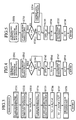
- Fig. 1 is a block diagram of an automatic door lock releasing apparatus according to a first embodiment of the present invention.
- Fig. 2 is a detailed configuration block diagram of the automatic door lock releasing apparatus of the first embodiment shown in Fig. 1.
- Fig. 3 is a flowchart illustrating normal operation of the automatic door lock releasing apparatus of the first embodiment shown in Figs. 1 and 2.
- Fig. 4 is a flowchart illustrating operation in decelerating direction integration processing.
- Fig. 5 is a flowchart illustrating operation in accelerating direction integration processing.
- Fig. 6 is a flowchart illustrating operation in integration processing.
- Fig. 7 is a flowchart illustrating operation in threshold value determination processing.
- Figs. 8A, 8B, 8C, and 8D are diagrams of assistance in explaining comparison of acceleration signals produced during collision and during non-collision.
- Figs. 9A, 9B, 9C, and 9D are diagrams of assistance in explaining comparison of root-mean-square values of acceleration signals produced during collision and during non-collision.
- Figs. 10A, 10B, 10C, 10D, 10E, and 10F are diagrams of assistance in explaining a method for collision determination.
- Figs. 11A, 11B, 11C, 11D, 11E, and 11F are diagrams of assistance in explaining waveforms of acceleration signals produced during travel on rough surfaces, which represent a non-collision.
- Figs. 12A, 12B, 12C, and 12D are diagrams of assistance in explaining a waveform of each acceleration signal produced in the automatic door lock releasing apparatus of the first embodiment during collision of a vehicle.
- Fig. 13 is a block diagram of an automatic door lock releasing apparatus according to a second embodiment of the present invention.
- Fig. 1 is a block diagram of an automatic door lock releasing apparatus 100 according to a first embodiment of the present invention.
- the automatic door lock releasing apparatus 100 is applied to a vehicle, for example.
- reference numeral 1 denotes an acceleration sensor (G sensor) that detects an X-direction acceleration Gx of a vehicle during a collision.
- Reference numeral 2 denotes a decelerating direction integrating means that integrates an acceleration signal Gx + of a decelerating direction obtained from an output Gx of the G sensor 1.
- Reference numeral 3 denotes an accelerating direction integrating means that integrates an acceleration signal Gx - of an accelerating direction obtained from the output Gx of the G sensor 1.
- Reference numeral 4 denotes a coefficient means (a first coefficient means) that performs weighting by multiplying an output of the accelerating direction integrating means 3 by a coefficient k 1 .
- Reference numeral 5 denotes a subtraction processing unit as a subtracting means that subtracts the output of the accelerating direction integrating means 3 weighted by the coefficient means 4 from an output of the decelerating direction integrating means 2.
- the weighting coefficient k 1 is a value set for the vehicle, while the X-direction denotes a direction in which the vehicle is moving, and a Y-direction denotes the lateral direction of the vehicle.
- Reference numeral 11 denotes an acceleration sensor (G sensor) that detects an acceleration Gy in a direction different from that of the G sensor 1 (hereinafter referred to as a Y-direction).
- Reference numeral 12 denotes a decelerating direction integrating means that integrates a deceleration signal Gy + of an accelerating direction obtained from an output Gy of the G sensor 11.
- Reference numeral 13 denotes an accelerating direction integrating means that integrates an acceleration signal Gy - of an accelerating direction obtained from the output Gy of the G sensor 11.
- Reference numeral 14 denotes a coefficient means (a first coefficient means) that performs weighting by multiplying an output of the accelerating direction integrating means 13 by a given coefficient k 2 .
- Reference numeral 15 denotes a subtraction processing unit as a subtracting means that subtracts the output of the accelerating direction integrating means 13 weighted by the coefficient means 14 from an output of the decelerating direction integrating means 12. It should be noted that the weighting coefficient k 2 is a value set for the vehicle.
- Reference numeral 6 denotes an arithmetic processing unit as an arithmetic processing means that calculates a resultant vector Vf on the basis of an output Vx of the subtraction processing unit 5 and an output Vy of the subtraction processing unit 15.
- Reference numeral 7 denotes a comparison processing unit as a signal generating means that compares the result of arithmetic processing obtained at the arithmetic processing unit 6 with a preset threshold value Vth. When the result Vf of arithmetic processing outputted from the arithmetic processing unit 6 exceeds the threshold value Vth, for example, the comparison processing unit generates a door lock release signal, and outputs the generated door lock release signal to a door mechanism of the vehicle.
- Reference numeral 16 denotes a trigger circuit for inputting X-direction and Y-direction acceleration signals from the G sensors 1 and 11.
- the trigger circuit starts respective decelerating direction integrating means 2 and 12, the accelerating direction integrating means 3 and 13, the coefficient means 4 and 14, the arithmetic processing unit 6, and the comparison processing unit 7, which are each shown in Fig. 1.
- respective decelerating direction integrating means 2 and 12, the accelerating direction integrating means 3 and 13, the coefficient means 4 and 14, the subtraction processing unit 5, the arithmetic processing unit 6, and the comparison processing unit 7, which are shown in Fig. 1, are realized by microcomputers and logical circuits, for example, and are included in an ECU (Electronic Control Unit) of the vehicle.
- ECU Electronic Control Unit
- Fig. 2 is a detailed configuration block diagram showing each component of the automatic door lock releasing apparatus according to the first embodiment as shown in Fig. 1.
- the decelerating direction integrating means 2 and 12 and the accelerating direction integrating means 3 and 13 are provided with positive side acceleration detecting means 21 and 31 and negative side acceleration detecting means 22 and 32, subtraction processing units 23, 24, 33, and 34, and integration processing units 25, 26, 35, and 36, respectively.
- the subtraction processing units 23, 24, 33, and 34 subtracts certain acceleration values ga, gb, gc, and gd from accelerations obtained at the positive side acceleration detecting means 21 and 31 and the negative side acceleration detecting means 22 and 32.
- the integration processing units 25, 26, 35, and 36 are provided with a function of setting integral values v outputted from the subtraction processing units 23, 24, 33, and 34 to an initial value of 0 when the integral values v are lower than a value 0 (hereinafter abbreviated as a reset function).
- the arithmetic processing unit 6 is an arithmetic unit for determining a resultant vector of X-direction and Y-direction integral values Vx and Vy.
- the arithmetic processing unit 6 is provided with square processing units 27 and 37, a coefficient means 38 (a second coefficient means) for weighting a velocity vy in the Y-direction, an addition processing unit 28 for adding an output of the square processing unit 27 and an output from the coefficient means 38, and a square root processing unit 39 for extracting the square root of an output from the addition processing unit 28.
- the comparison processing unit 7 comprises a comparator 30 that compares a preset threshold value Vth with a resultant vector Vf obtained at the arithmetic processing unit 6, and a one-shot timer 29 that generates and outputs a door lock release signal when the resultant vector value Vf is higher than the threshold value Vth.
- the threshold value Vth is a value inherent to the vehicle.
- FIG. 3 is a flowchart describing normal operation of the automatic door lock releasing apparatus for a vehicle according to the first embodiment as shown in Figs. 1 and 2.
- the flowchart illustrates processing performed in response to a timer interrupt at certain time intervals.
- the decelerating direction integrating means 2 determines a decelerating direction integral value va in the X-axis direction at a step ST31
- the accelerating direction integrating means 3 determines an accelerating direction integral value vb in the X-axis direction at a step ST32.
- a value obtained after the coefficient means 4 multiplied the accelerating direction integral value vb by a preset constant k 1 is subtracted from the decelerating direction integral value va by the subtraction processing unit 5.
- the obtained subtraction value is set to be Vx.
- the decelerating direction integrating means 12 determines a decelerating direction integral value vc in the Y-axis direction
- the accelerating direction integrating means 13 determines an accelerating direction integral value vd in the Y-axis direction.
- a value obtained after the coefficient means 14 multiplied the accelerating direction integral value vd by a preset constant k 2 is subtracted from the decelerating direction integral value vc by the subtraction processing unit 15.
- the obtained subtraction value is set to be Vy.
- a resultant vector Vf is determined from Vx obtained at the step ST33 and Vy obtained at the step ST36 multiplied by a preset constant K.
- the comparison processing unit 7 compares the resultant vector Vf with a preset threshold value Vth. If the resultant vector Vf exceeds the predetermined value, the one-shot timer 29 generates a door lock release signal, and thereby the timer interrupt is ended.
- Fig. 4 is a flowchart illustrating operation of the decelerating direction integrating means 2 and 12 in decelerating direction integration processing.
- decelerating direction integration will be described by using decelerating direction integration processing for an X-direction acceleration Gx as an example; however, decelerating direction integration processing for a Y-direction acceleration Gy is performed in the same manner.
- an X-direction acceleration signal obtained from the acceleration sensor 1 that detects an X-direction acceleration Gx of the vehicle is set to be a variable g.
- an inputted X-direction acceleration signal g is smaller than 0, the flow of the processing proceeds to a step ST44.
- the X-direction acceleration signal g is set to be 0, and then the flow of the processing proceeds to a step ST45.
- an offset ga is set to be an offset variable OFS.
- an integral value va is set to be an integral value V.
- step ST47 integration processing is performed.
- step ST48 the integral value V is set to be an integral value va, and thereby the decelerating direction integration processing is ended.
- Fig. 5 is a flowchart illustrating operation of the accelerating direction integrating means 3 and 13 in accelerating direction integration processing for an X-direction acceleration and a Y-direction acceleration.
- accelerating direction integration will be described below by using accelerating direction integration processing for an X-direction acceleration as an example.
- an output Gx - from the X-direction acceleration sensor 1 is set to be g.
- step ST53 when an inputted acceleration signal g is greater than 0, the flow of the processing proceeds to a step ST53-1.
- the acceleration signal g is set to be 0, and then the processing proceeds to a step ST55.
- step ST53 When it is determined at the step ST53 that the inputted acceleration signal g is smaller than 0, on the other hand, the flow of the processing proceeds to a step ST54.
- an offset gb is set to be an offset OFS.
- an integral value vb is set to be an integral value V.
- integration processing is performed by the integration processing unit 26.
- the integral value V is set to be an integral value vb, and thereby the decelerating direction integration processing for an X-direction acceleration is ended.
- Fig. 6 is a flowchart illustrating operation of the integration processing units 25, 26, 35, and 36 in the integration processing illustrated at the step ST47 in Fig. 4 and at the step ST57 in Fig. 5.
- a result of subtraction of the offset value OFS set at the step ST45 shown in Fig. 4 or at the step ST55 shown in Fig. 5 from the acceleration signal g is set to be an acceleration signal G.
- the integral value V set at the step ST46 shown in Fig. 4 or at the step ST56 shown in Fig. 5 is added to a product of sampling time T of the acceleration signal multiplied by the acceleration signal G.
- step ST63 when the integral value V is lower than 0, the flow of the processing proceeds to a step ST64, where the integral value V is reset to 0.
- step ST63 when the integral value V is higher than 0, the flow of the processing proceeds to the step ST48 in Fig. 4 or the step ST58 in Fig. 5.
- Fig. 7 is a flowchart illustrating operation of the comparison processing unit 7 in threshold value determination processing at the step ST38 shown in Fig. 3.
- a result of comparison by the comparator 30 is provided.
- an integral value Vf is lower than the threshold value Vth
- the flow of the processing proceeds to a step ST73. If a previous door lock release signal Sd is at a high level at the step ST73, it means that the falling edge of the door lock release signal Sd has been detected, and thus the flow of the processing proceeds to a step ST74.
- step ST74 when a certain time has passed since the falling of the door lock release signal Sd, the flow of the processing proceeds to a step ST75, where the door lock release signal Sd is set to an L level.
- the flow of the processing proceeds to a step ST72, where the door lock release signal Sd is set to an H level.
- Figs. 8A, 8B, 8C, and 8D are diagrams of assistance in explaining acceleration signals to be compared with one another that are obtained during vehicle collision and during non-collision.
- Figs. 8A and 8B show acceleration signals of a front-to-rear direction acceleration Gx and a side-to-side direction acceleration Gy of a vehicle, the signals being produced during medium speed and low speed collisions, at which a door lock should be released.
- Figs. 8C and 8D show acceleration signals produced during non-collision such as that of a hard hit at the bottom of a vehicle or that of travel on rough surfaces, at which a door lock should not be released.
- acceleration signals produced during collision and during non-collision will be compared with one another.
- the peak value of an (a) X-direction acceleration signal produced during a hard hit at the bottom of a vehicle as shown in Fig. 8C is lower than the peak value of an (a) X-direction acceleration signal produced during a medium speed collision as shown in Fig. 8A. However, it is higher than the peak value of an (a) X-direction acceleration signal produced during a low speed collision as shown in Fig. 8B.
- the peak value of an acceleration signal produced during a non-collision can be higher than the peak value of an acceleration signal produced during a collision, and therefore distinguishing between collision and non-collision by only acceleration peak values may result in a misjudgment; that is to say, it is extremely difficult to judge.
- Figs. 9A, 9B, 9C, and 9D are diagrams of assistance in explaining comparison of root-mean-square values of acceleration signals produced during collision and non-collision of a vehicle.
- the values shown in Figs. 9A, 9B, 9C, and 9D are obtained by squaring and then adding the respective accelerations Gx and Gy shown in Figs. 8A, 8B, 8C, and 8D.
- Fig. 9 the maximum value of an arithmetic result for a hard hit at the bottom of a vehicle as shown in Fig. 9C is compared with arithmetic results obtained from the conditions of a medium collision, a low speed collision, and travel on rough surfaces as shown in Figs. 9A, 9B, and 9D respectively.
- Fig 9 it is understood that even in judgement using sums of root-mean-square values of acceleration signals, it is difficult, as in the example shown in Fig. 8, to prevent an erroneous function of the door lock releasing apparatus during non-collision, and allow a door lock releasing system to judge correctly to activate the door lock releasing apparatus during collision.
- Figs. 10A, 10B, 10C, 10D, 10E, and 10F are diagrams of assistance in explaining a method for collision judgement employed in the automatic door lock releasing apparatus for a vehicle according to the present invention.
- Figs. 10A, 10B, 10C, 10D, 10E, and 10F show signal waveforms outputted from parts- of the automatic door lock releasing apparatus for a vehicle shown in Fig. 2 during a medium speed collision.
- Fig. 10A shows an output waveform of the G sensor 1.
- Fig. 10B shows an output waveform of the G sensor 11.
- Fig. 10C shows an output waveform Vx of the subtraction processing unit 5.
- the output waveform Vx is obtained when the coefficient means 4 multiplies an integration output waveform integrated at the integration processing unit 26 by a preset coefficient k 1 , and then an output waveform obtained by the multiplication is subtracted from an integration output waveform integrated at the integration processing unit 25.
- Fig. 10D shows an output waveform Vy of the subtraction processing unit 15.
- the output waveform Vx is obtained when an integration output waveform integrated by the integration processing unit 36 is multiplied by a preset coefficient k 2 at the coefficient means 14, and then a resulting output waveform is subtracted from an integration output waveform integrated by the integration processing unit 35.
- Fig. 10E shows a comparison between an output waveform Vf of the arithmetic processing unit 6 and a threshold value Vth.
- Fig. 10F shows the output waveform Vx of the subtraction processing unit 5 and the output waveform Vy of the subtraction processing unit 15, in which the locus of Vy is compared with the threshold value Vf.
- a door lock release signal Sd is outputted.
- Figs. 11A, 11B, 11C, 11D, 11E, and 11F are diagrams of assistance in explaining waveforms of acceleration signals produced during travel on rough surfaces, which represent a non-collision.
- Fig. 11A shows an output waveform Gx of the G sensor 1.
- Fig. 11B shows an output waveform Gy of the G sensor 11.
- Fig. 11C shows an output waveform Vx of the subtraction processing unit 5.
- Fig. 11D shows an output waveform Vy of the subtraction processing unit 15.
- Fig. 11E shows a comparison between an output waveform Vf of the arithmetic processing unit 6 and the threshold value Vth.
- Fig. 11F shows the output waveform Vx of the subtraction processing unit 5 and the output waveform Vy of the subtraction processing unit 15, in which the locus of Vx and Vy is compared with the threshold value Vf.
- An acceleration signal produced during non-collision such as that of travel on rough surfaces, hammering that results in a shock to the ECU itself, or a hard hit at the bottom of a vehicle, provides an output of a high-level acceleration signal of an accelerating direction as compared with normal collision.
- the acceleration signal during non-collision is characterized by alternate swings of its acceleration signal of a decelerating direction and its acceleration signal of an accelerating direction.
- the level of the acceleration signal of an accelerating direction is not necessarily equal to that of the acceleration signal of a decelerating direction.
- an integration waveform of an acceleration signal of an accelerating direction weighted by being multiplied by a coefficient is subtracted from an integration waveform obtained by integrating an acceleration signal of a decelerating direction, so that an integration waveform when the level of the acceleration signal of an accelerating direction is high is made small.
- Figs. 12A, 12B, 12C, and 12D are diagrams of assistance in explaining a waveform of each of the acceleration signals produced in the automatic door lock releasing apparatus of the first embodiment during collision of the vehicle.
- Figs. 12A, 12B, 12C, and 12D show output waveforms Vf of the arithmetic processing unit 6 in the conditions of medium speed collision, low speed collision, a hard hit at the bottom of the vehicle, and travel on rough surfaces, respectively.
- the automatic door lock releasing apparatus it is possible to prevent malfunction of the automatic door lock releasing apparatus for a vehicle during non-collision and activate a door lock releasing system correctly during collision.
- acceleration signal outputs of the X-direction and the Y-direction in response to the same impact may differ greatly from each other.
- the coefficient K shown in Fig. 2 used for the coefficient means 38 to weight a velocity Vy in the Y-direction is constant independently of the type of vehicle, it plays a role as a parameter that makes it possible to determine whether or not to automatically release the door lock of the vehicle with good responsivity even during a side collision and oblique collision.
- an acceleration sensor that detects an acceleration in a specified direction may be provided so that a door lock release signal can be generated by making a correct distinction between collision and non-collision.
- a plurality of acceleration signals are obtained from sensors detecting accelerations in a plurality of directions. Then an integration waveform of an acceleration signal of an accelerating direction weighted by being multiplied by a coefficient is subtracted from an integration waveform obtained by integrating one of the above acceleration signals of a decelerating direction, so that an integration waveform when the level of the acceleration signal of an accelerating direction is high is made small. Also a resultant vector is calculated so that an automatic door lock release signal is generated by clearly distinguishing between collision and non-collision. Therefore, it is possible to determine types of collisions in all directions on the basis of acceleration signals and thereby correctly generate a door lock release signal. Thus, it is possible to prevent malfunction in the processing for door lock release judgement, and also to quickly perform collision judgement.
- Fig. 13 is a block diagram of an automatic door lock releasing apparatus according to a second embodiment of the present invention.
- reference numeral 131 denotes an X-direction acceleration detecting G sensor.
- the acceleration sensor is provided for use in a passenger protection apparatus such as an air bag, for example.
- Reference numeral 8 denotes an X-direction collision determining means (a collision determining means).
- the X-direction collision determining means is supplied with an acceleration signal from the X-direction acceleration detecting G sensor 131, and accordingly generates a door lock release signal under the same conditions as in generation of a signal for activating a passenger protection apparatus during head-on collision of the vehicle.
- Reference numeral 141 denotes a Y-direction acceleration detecting G sensor, which also serves as an acceleration sensor provided for use in a passenger protection apparatus such as an air bag, for example.
- Reference numeral 9 denotes a Y-direction collision determining means.
- the Y-direction collision determining means is supplied with an acceleration signal from the Y-direction acceleration detecting G sensor 141, and accordingly generates a door lock release signal under the same conditions as in generation of a signal for activating a passenger protection apparatus during head-on collision of the vehicle.
- Reference numeral 10 denotes a logical sum means.
- the logical sum means 10 is supplied with door lock release signals from the X-direction collision determining means 8, the comparison processing unit 7, and the Y-direction collision determining means 9, accordingly calculates a logical sum on the basis of the above, and then outputs a door lock release signal resulting from the calculation to the outside.
- the X-direction collision determining means 8 is supplied with an acceleration signal obtained from the X-direction acceleration detecting G sensor 131, determines activation of the passenger protection apparatus such as an air bag during head-on collision of the vehicle, and generates an activation signal.
- the X-direction collision determining means- 8 when an acceleration in the X-direction that is at a sufficient level to activate the passenger protection apparatus is supplied from the X-direction acceleration detecting G sensor 131, the X-direction collision determining means- 8 generates a door lock release signal Sd, and then outputs it to the logical sum means 10.
- the Y-direction collision determining means 9 is supplied with an acceleration signal obtained from the Y-direction acceleration detecting G sensor 141, determines activation of the passenger protection apparatus such as an air bag during head-on collision of the vehicle, and generates an activation signal.
- the Y-direction collision determining means 9 generates a door lock release signal Sd, and then outputs it to the logical sum means 10.
- the logical sum means 10 calculates a logical sum of output signals from the X-direction collision determining means 8 and the Y-direction collision determining means 9 and an output signal outputted from the comparison processing unit 7 described in the first embodiment, and then outputs a door lock release signal Sd to the outside.
- the second embodiment is configured in such a way that G sensors for a passenger protection apparatus are also used for the second embodiment, and a means for determining output of a signal to start the passenger protection apparatus is added in order to generate a door lock release signal.
- the second embodiment has an effect of enabling simple configuration of the apparatus.
- the automatic door lock releasing apparatus makes it possible to determine types of collisions in all directions on the basis of acceleration signals; that is, it is possible to generate an automatic door lock release signal by making correct determination during collision and during non-collision.
- the automatic door lock releasing apparatus makes it possible to prevent an erroneous function in processing for door lock release determination, and hence it is applicable to transportation vehicles and other fields as a highly reliable apparatus that determines the occurrence of a collision quickly.
Landscapes
- Engineering & Computer Science (AREA)
- Mechanical Engineering (AREA)
- Lock And Its Accessories (AREA)
- Air Bags (AREA)
Abstract
Description
Claims (7)
- An automatic door lock releasing apparatus comprising:a plurality of acceleration sensors for detecting acceleration in a plurality of directions;a plurality of decelerating direction integrating means each provided in correspondence with one of said plurality of acceleration sensors for integrating an acceleration signal of a decelerating direction within a specified sampling time, said acceleration signal being included in each of acceleration signals of the plurality of directions obtained from said plurality of acceleration sensors;a plurality of accelerating direction integrating means each provided in correspondence with one of said plurality of acceleration sensors for integrating an acceleration signal of an accelerating direction within a specified sampling time, said acceleration signal being included in each of acceleration signals of said plurality of directions obtained from said plurality of acceleration sensors;a plurality of first coefficient means each provided in correspondence with one of said plurality of acceleration sensors for weighting an output of said accelerating direction integrating means by multiplying it by a specified coefficient;a plurality of subtracting means each provided in correspondence with one of said plurality of acceleration sensors for determining a velocity signal by subtracting said integral value outputted from said first coefficient means from said integral value outputted from said decelerating direction integrating means;an arithmetic processing means for receiving a plurality of velocity signals outputted from said plurality of subtracting means and determining a resultant velocity of said plurality of velocity signals; anda signal generating means for comparing said resultant velocity outputted from said arithmetic processing means with a specified threshold value and generating and outputting a start signal when said resultant velocity exceeds said specified threshold value.
- An automatic door lock releasing apparatus as claimed in claim 1,
wherein the decelerating direction integrating means includes:a positive side acceleration detecting means for detecting a positive side acceleration included in the acceleration signals obtained from the plurality of acceleration sensors; andan integration processing unit for integrating an input of said positive side acceleration outputted from said positive side acceleration detecting means and thereby calculating an integral value of said positive side acceleration. - An automatic door lock releasing apparatus as claimed in claim 1,
wherein the accelerating direction integrating means includes:a negative side acceleration detecting means for detecting a negative side acceleration included in the acceleration signals obtained from the plurality of acceleration sensors; andan integration processing unit for integrating an input of said negative side acceleration outputted from said negative side acceleration detecting means and thereby calculating an integral value of said negative side acceleration. - An automatic door lock releasing apparatus as claimed in claim 1,
wherein the arithmetic processing means includes:a plurality of square processing units each provided in correspondence with one of the plurality of subtracting means for squaring a velocity signal outputted from each of said plurality of subtracting means;a second coefficient means for weighting an output from part of said plurality of square processing units by multiplying it by a specified value;an addition processing unit for adding outputs of said plurality of square processing units and said second coefficient means; anda square root processing unit for determining a square root value of an output of said addition processing unit. - An automatic door lock releasing apparatus as claimed in claim 1,
wherein the signal generating means includes:a comparator for comparing the resultant velocity outputted from the arithmetic processing unit with a specified threshold value; anda one-shot timer for generating and outputting said start signal according to an output from said comparator. - An automatic door lock releasing apparatus as claimed in claim 1,wherein part of the plurality of acceleration sensors are acceleration sensors for a passenger protection apparatus; andwherein the automatic door lock releasing apparatus further includes a collision determining means for receiving an input of an acceleration signal outputted from an acceleration sensor for said passenger protection apparatus and outputting a start signal when said acceleration signal exceeds a specified value.
- An automatic door lock releasing apparatus as claimed in claim 6, further including a logical sum means for calculating a logical sum of the start signal from the signal generating means and said start signal from the collision determining means.
Applications Claiming Priority (1)
| Application Number | Priority Date | Filing Date | Title |
|---|---|---|---|
| PCT/JP1999/003430 WO2001000955A1 (en) | 1999-06-25 | 1999-06-25 | Automatic door lock releasing device |
Publications (3)
| Publication Number | Publication Date |
|---|---|
| EP1108836A1 true EP1108836A1 (en) | 2001-06-20 |
| EP1108836A4 EP1108836A4 (en) | 2007-05-02 |
| EP1108836B1 EP1108836B1 (en) | 2008-10-22 |
Family
ID=14236076
Family Applications (1)
| Application Number | Title | Priority Date | Filing Date |
|---|---|---|---|
| EP99973937A Expired - Lifetime EP1108836B1 (en) | 1999-06-25 | 1999-06-25 | Automatic door lock releasing device |
Country Status (5)
| Country | Link |
|---|---|
| US (1) | US6411875B2 (en) |
| EP (1) | EP1108836B1 (en) |
| JP (1) | JP3764101B2 (en) |
| DE (1) | DE69939780D1 (en) |
| WO (1) | WO2001000955A1 (en) |
Cited By (2)
| Publication number | Priority date | Publication date | Assignee | Title |
|---|---|---|---|---|
| EP1566505A1 (en) * | 2004-02-20 | 2005-08-24 | Audi Ag | Security device for a vehicle |
| FR2951488A1 (en) * | 2009-10-16 | 2011-04-22 | Peugeot Citroen Automobiles Sa | Opening frames e.g. front and rear doors, locking/unlocking control system, for motor vehicle i.e. car, has control unit to control locking/unlocking of opening frames, when parameter e.g. deceleration, exceeds threshold value |
Families Citing this family (5)
| Publication number | Priority date | Publication date | Assignee | Title |
|---|---|---|---|---|
| JP2003269028A (en) * | 2002-03-18 | 2003-09-25 | Aisin Seiki Co Ltd | Door unlocking device |
| DE10245781A1 (en) * | 2002-10-01 | 2004-04-15 | Robert Bosch Gmbh | Method for triggering a restraint system in a vehicle |
| JP4415710B2 (en) * | 2004-03-11 | 2010-02-17 | トヨタ自動車株式会社 | Open / close control device |
| DE102004024265B4 (en) * | 2004-05-15 | 2014-07-17 | Daimler Ag | Security system for operating at least one electrically operable closure device of a door of a vehicle |
| WO2015194109A1 (en) * | 2014-06-17 | 2015-12-23 | マツダ株式会社 | Vehicular emergency alert device |
Family Cites Families (7)
| Publication number | Priority date | Publication date | Assignee | Title |
|---|---|---|---|---|
| FR2504474A1 (en) * | 1981-04-28 | 1982-10-29 | Renault | METHOD AND SYSTEM FOR COLLISION DETECTION AND CONTROL OF SECURITY DEVICES |
| JP2610620B2 (en) | 1987-07-27 | 1997-05-14 | 三菱瓦斯化学 株式会社 | Resin composition with excellent heat and solvent resistance |
| JP3118980B2 (en) * | 1992-09-21 | 2000-12-18 | 日本電気株式会社 | Vehicle collision determination device |
| JPH06234342A (en) | 1993-02-10 | 1994-08-23 | Toyota Motor Corp | Central control device at the time of collision |
| JP2941643B2 (en) * | 1994-04-14 | 1999-08-25 | 三菱自動車工業株式会社 | Starting device for occupant protection device |
| JPH08135273A (en) | 1994-11-11 | 1996-05-28 | Frontier:Kk | Door lock releasing device for automobile |
| JP3204180B2 (en) * | 1996-10-23 | 2001-09-04 | 日本電気株式会社 | Vehicle collision determination method and collision determination device |
-
1999
- 1999-06-25 EP EP99973937A patent/EP1108836B1/en not_active Expired - Lifetime
- 1999-06-25 WO PCT/JP1999/003430 patent/WO2001000955A1/en not_active Ceased
- 1999-06-25 JP JP2001506346A patent/JP3764101B2/en not_active Expired - Fee Related
- 1999-06-25 DE DE69939780T patent/DE69939780D1/en not_active Expired - Lifetime
-
2001
- 2001-02-26 US US09/791,543 patent/US6411875B2/en not_active Expired - Lifetime
Cited By (2)
| Publication number | Priority date | Publication date | Assignee | Title |
|---|---|---|---|---|
| EP1566505A1 (en) * | 2004-02-20 | 2005-08-24 | Audi Ag | Security device for a vehicle |
| FR2951488A1 (en) * | 2009-10-16 | 2011-04-22 | Peugeot Citroen Automobiles Sa | Opening frames e.g. front and rear doors, locking/unlocking control system, for motor vehicle i.e. car, has control unit to control locking/unlocking of opening frames, when parameter e.g. deceleration, exceeds threshold value |
Also Published As
| Publication number | Publication date |
|---|---|
| US20010007963A1 (en) | 2001-07-12 |
| EP1108836A4 (en) | 2007-05-02 |
| JP3764101B2 (en) | 2006-04-05 |
| DE69939780D1 (en) | 2008-12-04 |
| EP1108836B1 (en) | 2008-10-22 |
| WO2001000955A1 (en) | 2001-01-04 |
| US6411875B2 (en) | 2002-06-25 |
Similar Documents
| Publication | Publication Date | Title |
|---|---|---|
| US5815393A (en) | Airbag deployment control apparatus for vehicle and the method | |
| EP1270337B1 (en) | A rollover-sensing system for a vehicle and method of operating the same | |
| US6438475B1 (en) | Crash detection system | |
| US6167335A (en) | Vehicular occupant protection system and crash mode determining unit thereof | |
| US7737833B2 (en) | Pedestrian collision detection apparatus and pedestrian protection system | |
| US5521822A (en) | Method for controlling actuation of a vehicle safety device using filtered vehicle deceleration data | |
| KR960013853A (en) | Collision type discrimination device for automobile using 3-way (3-axis) deceleration signal | |
| US6005479A (en) | Side impact passenger protection system for vehicle and crash determination device of same | |
| WO1996009942A1 (en) | A safety arrangement | |
| EP1000820B1 (en) | Passive restraint control system for vehicles | |
| US6636794B2 (en) | Passive safety system | |
| US6363308B1 (en) | Satellite crash sensor and method with constant and dynamic thresholds for multi-stage restraint deployment | |
| EP1108836B1 (en) | Automatic door lock releasing device | |
| JP3829445B2 (en) | Vehicle side collision occupant protection system and collision determination device | |
| JPWO2001000955A1 (en) | Automatic door lock release device | |
| JPH07251702A (en) | Method of operating vehicle occupant protecting device | |
| KR100458749B1 (en) | Vehicle crash determining apparatus | |
| JP4003003B2 (en) | Side airbag device | |
| KR960021947A (en) | Control system and method for airbag deployment, non-development situation determination and optimal start time determination | |
| EP0711232B1 (en) | Method and System for Discrimitating long-period, low-velocity Crashes | |
| EP0782514A1 (en) | Method for damping crash-discrimination measures | |
| KR100362098B1 (en) | Collision detecting method for operating automobile air bag | |
| JPH11278208A (en) | Collision determining device for air bag system | |
| JPH0958406A (en) | Actuation device for vehicle occupant protection device | |
| JPH0585298A (en) | Operation control device for passenger protection device |
Legal Events
| Date | Code | Title | Description |
|---|---|---|---|
| PUAI | Public reference made under article 153(3) epc to a published international application that has entered the european phase |
Free format text: ORIGINAL CODE: 0009012 |
|
| 17P | Request for examination filed |
Effective date: 20010220 |
|
| AK | Designated contracting states |
Kind code of ref document: A1 Designated state(s): DE IT |
|
| RAP1 | Party data changed (applicant data changed or rights of an application transferred) |
Owner name: MITSUBISHI DENKI KABUSHIKI KAISHA |
|
| A4 | Supplementary search report drawn up and despatched |
Effective date: 20070221 |
|
| GRAP | Despatch of communication of intention to grant a patent |
Free format text: ORIGINAL CODE: EPIDOSNIGR1 |
|
| RIC1 | Information provided on ipc code assigned before grant |
Ipc: B60R 21/00 20060101ALI20080704BHEP Ipc: E05B 65/20 20060101AFI20080704BHEP |
|
| GRAS | Grant fee paid |
Free format text: ORIGINAL CODE: EPIDOSNIGR3 |
|
| GRAA | (expected) grant |
Free format text: ORIGINAL CODE: 0009210 |
|
| AK | Designated contracting states |
Kind code of ref document: B1 Designated state(s): DE IT |
|
| REF | Corresponds to: |
Ref document number: 69939780 Country of ref document: DE Date of ref document: 20081204 Kind code of ref document: P |
|
| PLBE | No opposition filed within time limit |
Free format text: ORIGINAL CODE: 0009261 |
|
| STAA | Information on the status of an ep patent application or granted ep patent |
Free format text: STATUS: NO OPPOSITION FILED WITHIN TIME LIMIT |
|
| PG25 | Lapsed in a contracting state [announced via postgrant information from national office to epo] |
Ref country code: IT Free format text: LAPSE BECAUSE OF FAILURE TO SUBMIT A TRANSLATION OF THE DESCRIPTION OR TO PAY THE FEE WITHIN THE PRESCRIBED TIME-LIMIT Effective date: 20081022 |
|
| 26N | No opposition filed |
Effective date: 20090723 |
|
| REG | Reference to a national code |
Ref country code: DE Ref legal event code: R084 Ref document number: 69939780 Country of ref document: DE Effective date: 20110506 Ref country code: DE Ref legal event code: R084 Ref document number: 69939780 Country of ref document: DE Effective date: 20110705 |
|
| PGFP | Annual fee paid to national office [announced via postgrant information from national office to epo] |
Ref country code: DE Payment date: 20170621 Year of fee payment: 19 |
|
| REG | Reference to a national code |
Ref country code: DE Ref legal event code: R119 Ref document number: 69939780 Country of ref document: DE |
|
| PG25 | Lapsed in a contracting state [announced via postgrant information from national office to epo] |
Ref country code: DE Free format text: LAPSE BECAUSE OF NON-PAYMENT OF DUE FEES Effective date: 20190101 |