EP1108526A2 - Method and apparatus for manufacturing a tire ply and its application in tire manufacturing - Google Patents
Method and apparatus for manufacturing a tire ply and its application in tire manufacturing Download PDFInfo
- Publication number
- EP1108526A2 EP1108526A2 EP00126679A EP00126679A EP1108526A2 EP 1108526 A2 EP1108526 A2 EP 1108526A2 EP 00126679 A EP00126679 A EP 00126679A EP 00126679 A EP00126679 A EP 00126679A EP 1108526 A2 EP1108526 A2 EP 1108526A2
- Authority
- EP
- European Patent Office
- Prior art keywords
- tube
- flat sheet
- cutting
- edges
- splicing
- Prior art date
- Legal status (The legal status is an assumption and is not a legal conclusion. Google has not performed a legal analysis and makes no representation as to the accuracy of the status listed.)
- Granted
Links
Images




Classifications
-
- B—PERFORMING OPERATIONS; TRANSPORTING
- B29—WORKING OF PLASTICS; WORKING OF SUBSTANCES IN A PLASTIC STATE IN GENERAL
- B29D—PRODUCING PARTICULAR ARTICLES FROM PLASTICS OR FROM SUBSTANCES IN A PLASTIC STATE
- B29D30/00—Producing pneumatic or solid tyres or parts thereof
- B29D30/06—Pneumatic tyres or parts thereof (e.g. produced by casting, moulding, compression moulding, injection moulding, centrifugal casting)
- B29D30/38—Textile inserts, e.g. cord or canvas layers, for tyres; Treatment of inserts prior to building the tyre
- B29D30/46—Cutting textile inserts to required shape
-
- B—PERFORMING OPERATIONS; TRANSPORTING
- B29—WORKING OF PLASTICS; WORKING OF SUBSTANCES IN A PLASTIC STATE IN GENERAL
- B29C—SHAPING OR JOINING OF PLASTICS; SHAPING OF MATERIAL IN A PLASTIC STATE, NOT OTHERWISE PROVIDED FOR; AFTER-TREATMENT OF THE SHAPED PRODUCTS, e.g. REPAIRING
- B29C53/00—Shaping by bending, folding, twisting, straightening or flattening; Apparatus therefor
- B29C53/36—Bending and joining, e.g. for making hollow articles
- B29C53/38—Bending and joining, e.g. for making hollow articles by bending sheets or strips at right angles to the longitudinal axis of the article being formed and joining the edges
- B29C53/48—Bending and joining, e.g. for making hollow articles by bending sheets or strips at right angles to the longitudinal axis of the article being formed and joining the edges for articles of indefinite length, i.e. bending a strip progressively
- B29C53/50—Bending and joining, e.g. for making hollow articles by bending sheets or strips at right angles to the longitudinal axis of the article being formed and joining the edges for articles of indefinite length, i.e. bending a strip progressively using internal forming surfaces, e.g. mandrels
-
- B—PERFORMING OPERATIONS; TRANSPORTING
- B29—WORKING OF PLASTICS; WORKING OF SUBSTANCES IN A PLASTIC STATE IN GENERAL
- B29D—PRODUCING PARTICULAR ARTICLES FROM PLASTICS OR FROM SUBSTANCES IN A PLASTIC STATE
- B29D30/00—Producing pneumatic or solid tyres or parts thereof
- B29D30/06—Pneumatic tyres or parts thereof (e.g. produced by casting, moulding, compression moulding, injection moulding, centrifugal casting)
- B29D30/08—Building tyres
- B29D30/20—Building tyres by the flat-tyre method, i.e. building on cylindrical drums
- B29D30/24—Drums
- B29D30/26—Accessories or details, e.g. membranes, transfer rings
- B29D30/2607—Devices for transferring annular tyre components during the building-up stage, e.g. from the first stage to the second stage building drum
-
- B—PERFORMING OPERATIONS; TRANSPORTING
- B29—WORKING OF PLASTICS; WORKING OF SUBSTANCES IN A PLASTIC STATE IN GENERAL
- B29D—PRODUCING PARTICULAR ARTICLES FROM PLASTICS OR FROM SUBSTANCES IN A PLASTIC STATE
- B29D30/00—Producing pneumatic or solid tyres or parts thereof
- B29D30/06—Pneumatic tyres or parts thereof (e.g. produced by casting, moulding, compression moulding, injection moulding, centrifugal casting)
- B29D30/38—Textile inserts, e.g. cord or canvas layers, for tyres; Treatment of inserts prior to building the tyre
- B29D30/42—Endless textile bands without bead-rings
-
- B—PERFORMING OPERATIONS; TRANSPORTING
- B29—WORKING OF PLASTICS; WORKING OF SUBSTANCES IN A PLASTIC STATE IN GENERAL
- B29D—PRODUCING PARTICULAR ARTICLES FROM PLASTICS OR FROM SUBSTANCES IN A PLASTIC STATE
- B29D30/00—Producing pneumatic or solid tyres or parts thereof
- B29D30/06—Pneumatic tyres or parts thereof (e.g. produced by casting, moulding, compression moulding, injection moulding, centrifugal casting)
- B29D30/38—Textile inserts, e.g. cord or canvas layers, for tyres; Treatment of inserts prior to building the tyre
- B29D30/42—Endless textile bands without bead-rings
- B29D2030/421—General aspects of the joining methods and devices for creating the bands
-
- B—PERFORMING OPERATIONS; TRANSPORTING
- B29—WORKING OF PLASTICS; WORKING OF SUBSTANCES IN A PLASTIC STATE IN GENERAL
- B29L—INDEXING SCHEME ASSOCIATED WITH SUBCLASS B29C, RELATING TO PARTICULAR ARTICLES
- B29L2030/00—Pneumatic or solid tyres or parts thereof
- B29L2030/003—Plies; Breakers
- B29L2030/004—Carcasses
-
- Y—GENERAL TAGGING OF NEW TECHNOLOGICAL DEVELOPMENTS; GENERAL TAGGING OF CROSS-SECTIONAL TECHNOLOGIES SPANNING OVER SEVERAL SECTIONS OF THE IPC; TECHNICAL SUBJECTS COVERED BY FORMER USPC CROSS-REFERENCE ART COLLECTIONS [XRACs] AND DIGESTS
- Y10—TECHNICAL SUBJECTS COVERED BY FORMER USPC
- Y10T—TECHNICAL SUBJECTS COVERED BY FORMER US CLASSIFICATION
- Y10T156/00—Adhesive bonding and miscellaneous chemical manufacture
- Y10T156/10—Methods of surface bonding and/or assembly therefor
- Y10T156/1002—Methods of surface bonding and/or assembly therefor with permanent bending or reshaping or surface deformation of self sustaining lamina
- Y10T156/1036—Bending of one piece blank and joining edges to form article
- Y10T156/1038—Hollow cylinder article
Definitions
- This invention relates to the shaping of a sheet of calendered steel wire ply material into a tubular ply member and transferring the tubular ply member over a mandrel to an anvil, cutting the tubular member with a rotating knife to a required width for a tire ply and transferring the cut length to a tire building drum. Stretching of the ply during application to the drum is avoided and an exact wire count in the ply is provided. Also the desired width of the ply sheet material may be provided by splicing two calendered sheets with the sum of their widths equal to the circumference of the ply material.
- the present invention is directed to guiding flat wire reinforced calendered sheet material through shaping rollers where it is shaped into a tube with opposite edges in abutting relation.
- the edges are spliced to form the tube which is cut to length and transferred to a tire building drum.
- Different width sheets may be spliced to form a sheet having a width greater than either of the spliced sheets so that a tube of the desired diameter may be obtained.
- a method of forming a tube of reinforced elastomeric material characterized by shaping a flat sheet of reinforced elastomeric material having a width equal to the circumference of the tube into a tubular shape splicing abutting edges of the sheet and cutting the tube into a predetermined band length for application to a tire building drum.
- a method of building a tire comprising applying an inner liner to an expandable tire building drum characterized by:
- apparatus for forming a tubular band of reinforced elastomeric material having a predetermined length and diameter from a flat sheet of reinforced elastomeric material characterized by:
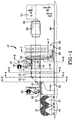
- Fig. 1 is a side elevation of an apparatus embodying the invention showing the sheets of calendered wire reinforced material positioned for splicing with a flat edge splicer, a tube shaping apparatus with a tubular splicer and a transfer and cutting apparatus for carrying a spliced tubular reinforced tire component to a cutting position and to a tire building band drum.
- Fig. 2 is a plan view of the apparatus shown in Fig. 1 showing the telescopic end of the mandrel in the extended position.
- Fig. 3 is a sectional view taken along the plane of line 3-3 in Fig. 1.
- Fig. 4 is a sectional view taken along the plane of line 4-4 in Fig. 1.
- Fig. 5 is a sectional view taken along the plane of line 5-5 in Fig. 1.
- Fig. 6 is a sectional view taken along the plane of line 6-6 in Fig. 1.
- Fig. 7 is a sectional view taken along the plane of line 7-7 in Fig. 1.
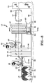
- Fig. 8 is an elevation like Fig. 1 showing the apparatus at the tubular reinforced tire component has been transferred to the tire building drum.
- Fig. 9 is a fragmentary sectional view of the telescopic end of the mandrel as shown in Fig. 1.
- Fig. 10 is a view like Fig. 9 showing the telescopic end of the mandrel in the retracted position.
- a tube forming apparatus 10 for forming a tubular band 12 of reinforced elastomeric material from a flat sheet 14 of wire reinforced rubber ply material of a width W1 equal to the circumference of the tubular band.
- the sheet 14 may be reinforced by wires 16 extending longitudinally of the sheet.
- the sheet 14 may be prespliced from a first sub flat sheet 18 and a second sub flat sheet 20 having widths of W2 and W3 respectively, by a flat sheet splicer roller 22 mounted on a splicing table 24.
- a gum strip 26 may be supplied to the splicer roll 22 for making the splice between the edges of the sub flat sheets 18 and 20.
- the sub flat sheets 18 and 20 may be supplied from first and second calendered stock sub let offs 19 and 21 which are rolled into position at one end of the tube forming apparatus 10.
- tube forming frames 28 and 30 are mounted on a base member 32 and have support forming rollers 34 for shaping the sheet 14 in a tubular form shown in Fig. 5.
- a third tube forming frame 36 shown in Fig. 5, also has forming rolls 34 for providing the tubular shape 14.
- the third tube forming frame 36 also supports a splicer roll 38 for splicing edges 40 and 42 of the sheet 14 to provide a tube 44.
- a mandrel 46 is mounted on a hanger support 47 fastened to the second tube forming frame 30.
- the hanger support 47 has a bore 48 for supporting a mandrel shaft 49.
- the mandrel 46 extends downstream to a position under the splicer roll 38 where a mandrel splicer roll 50 is rotatably mounted to cooperate with the third tube forming frame splicer roll 38 for splicing the edges 40 and 42.
- a gum strip 52 may be supplied to the splicer roll 38 for completing the splice of the edges 40 and 42.
- an anvil 54 Downstream from the splicer rolls 48 and 50, an anvil 54 is mounted on the mandrel 46 for engagement by a rotating cutter 56 having a cutting blade 58 movable into engagement with the anvil for cutting the tube at a predetermined position A-A, shown in Fig. 8.
- the cutter 56 As shown in Fig. 6, the cutter 56 is mounted on a base 57.
- the tube 44 is gripped by magnetic shoes 58 of a transfer mechanism 60.
- the magnetic shoes 58 are slidably mounted for radial movement in response to circumferential movement of a ring 61 actuated by a piston cylinder 63 for rotating the ring.
- Bars 64 are mounted in positions between the shoes 58 so that when the shoes are retracted, the bars will release the cut tubular band 12 from the shoes.
- the transfer mechanism 60 is movable on base 57 having wheels 64 supported on rails 66 mounted on the base.
- the shoes 58 are magnetized and radially contracted to grip the tubular band 12 and are movable with the transfer mechanism 60 to a position over a drum 68 mounted on a housing 70 of a tire building machine.
- the housing 70 may be rotated or movable to another station for transferring the tubular band 12 to another drum where other components may be added.
- an inner liner 69 may be applied to the drum 68 prior to applying the tubular band 12.
- the spliced tube 44 is gripped by the shoes 58 of the transfer mechanism and pulled from a position shown in Fig. 1 to a position shown in Fig. 8 where the tubular band 12 is cut to length by the rotating cutter 56.
- the band 12 is then transferred to the drum 68 by the transfer mechanism 60.
- the housing 70 may be rotated or movable to another station for transferring the tubular band 12 to another drum where other components may be added.
- an inner liner 69 may be applied to the drum 68 prior to applying the tubular band 12.
- the drum 68 may be expanded and the shoes 58 retracted, positioning the band 12 on the drum as shown in Figs. 8.
- alternative splicing rolls 72 are provided in place of splicer roll 38 and mandrel spacer roll 50.
- the splicing rolls 72 are mounted on an arm 74 attached to the third tube forming frame and supporting shafts 76 for the rolls.
- the shafts 76 are converging from a central position over the splice to positions spaced from the splice.
- the rolls 72 each have a frustro conical grooved surface which urges the edges 41 and 42 together.
- the transfer mechanism 60 then transfers the tubular band 12 to the drum 68 where the drum is expanded to grip the tubular band.
- the shoes 58 of the transfer mechanism 60 are then retracted and the mechanism moved away from the drum 68.
- the drum 68 may be moved to another position where the inner liner 69 and tubular band 12 are joined with other tire components to provide a green tire assembly.
- an adjustable tubular extension 80 may be threaded into the end of the mandrel 46 a shown in Figs. 9 and 10. By rotating the extension 80 it may be adjusted axially between an elongated position for wide tubular bands 12 shown in Fig. 9 and narrow tubular bands 12 shown in Fig. 10.
Landscapes
- Engineering & Computer Science (AREA)
- Mechanical Engineering (AREA)
- Textile Engineering (AREA)
- Tyre Moulding (AREA)
- Lining Or Joining Of Plastics Or The Like (AREA)
- Treatment Of Fiber Materials (AREA)
Abstract
Description
Claims (10)
- A method of forming a tube of reinforced elastomeric material comprising shaping a flat sheet of reinforced elastomeric material having a width equal to the circumference of said tube into a tubular shape, splicing abutting edges of said sheet and cutting said tube into a predetermined band length for application to a tire building drum.
- The method of claim 1 further comprising said flat sheet being reinforced by wires extending longitudinally of said flat sheet whereby said wires at said edges are in abutting relationship after splicing of said edges.
- The method of claim 2 further comprising transferring said tube cut to said predetermined band length to a cylindrical mandrel after splicing and then cutting said tube by engagement of a cutting blade with an anvil on said mandrel.
- The method of building a tire wherein an inner liner is applied to an expandable tire building drum comprising:a. shaping a tube from a flat sheet of wire reinforced elastomeric material having a width equal to the circumference of said tube,b. splicing the edges of said flat sheet with said reinforcing wires in said edges being in abutting relation,c. cutting said tube into a tubular member of a predetermined band length,d. transferring said tubular member to a position over said inner liner, ande. applying other tire components over said tubular member.
- The method of claim 4 further comprising moving said tire building drum from a first position for applying said inner liner to a second position for applying said tube.
- Apparatus for forming a tubular band of reinforced elastomeric material having a predetermined length and diameter from a flat sheet of reinforced elastomeric material, characterized by:(a) a tube former for shaping a flat sheet into a tubular member having a circumference equal to the width of said flat sheet,(b) a splicer for splicing abutting edges of said sheet at a splicing position located downstream of said tube former,(c) a cutting apparatus for cutting said tubular member to a predetermined length , located at a cutting position downstream from said splicer;(d) a cylindrical mandrel supporting said tubular member at a position downstream from said splicer as it is being transferred to said cutting apparatus,(e) an anvil mounted on said mandrel at said cutting position, and(f) a transfer mechanism for gripping said tubular member and moving said tubular member axially of said mandrel.
- Apparatus in accordance with claim 6 further characterized by said anvil being mounted on said mandrel adjacent said cutting apparatus for engagement by a cutting blade of said cutting apparatus.
- Apparatus in accordance with claim 6 wherein said calendered stock letoff comprises a first sub let off and a second sub letoff for storing a first sub flat sheet and a second sub flat sheet with the sum of the widths of said first sub flat sheet and said second sub let off being equal to the circumference of said tubular band, further characterized by a splicer for splicing edges of said first sub flat sheet and said second sub flat sheet to provide said flat sheet for said tube former.
- Apparatus in accordance with claim 6 further characterized by said splicer being located over of said mandrel for splicing said abutting edges of said sheet as said sheet is moved by said transfer mechanism to said cutting position.
- Apparatus in accordance with claim 9 further characterized by said splicer having two splicing rollers with converging axes positioned over said abutting edges and having bevel gear surfaces for urging said edges together upon contact of said rollers with said edges.
Applications Claiming Priority (2)
| Application Number | Priority Date | Filing Date | Title |
|---|---|---|---|
| US09/460,671 US6364981B1 (en) | 1999-12-14 | 1999-12-14 | Forming and application of tire ply |
| US460671 | 1999-12-14 |
Publications (3)
| Publication Number | Publication Date |
|---|---|
| EP1108526A2 true EP1108526A2 (en) | 2001-06-20 |
| EP1108526A3 EP1108526A3 (en) | 2003-03-26 |
| EP1108526B1 EP1108526B1 (en) | 2005-06-29 |
Family
ID=23829619
Family Applications (1)
| Application Number | Title | Priority Date | Filing Date |
|---|---|---|---|
| EP00126679A Expired - Lifetime EP1108526B1 (en) | 1999-12-14 | 2000-12-05 | Method and apparatus for manufacturing a reinforced tubular ply member for a tire |
Country Status (6)
| Country | Link |
|---|---|
| US (1) | US6364981B1 (en) |
| EP (1) | EP1108526B1 (en) |
| JP (1) | JP2001198987A (en) |
| BR (1) | BR0005728A (en) |
| CA (1) | CA2326768C (en) |
| DE (1) | DE60021047T2 (en) |
Cited By (2)
| Publication number | Priority date | Publication date | Assignee | Title |
|---|---|---|---|---|
| EP1323516A1 (en) * | 2001-12-28 | 2003-07-02 | Société de Technologie Michelin | Process for manufacturing tyres |
| WO2023218076A1 (en) * | 2022-05-12 | 2023-11-16 | Retyre As | Joining a tyre base layer |
Families Citing this family (7)
| Publication number | Priority date | Publication date | Assignee | Title |
|---|---|---|---|---|
| JP3995956B2 (en) * | 2002-02-26 | 2007-10-24 | 不二精工株式会社 | Pneumatic tire and manufacturing method thereof |
| US7073552B2 (en) * | 2002-12-20 | 2006-07-11 | The Goodyear Tire & Rubber Company | Tire preparation ply manufacturing apparatus and method |
| JP2011518693A (en) * | 2008-04-23 | 2011-06-30 | ミシュラン ルシェルシュ エ テクニーク ソシエテ アノニム | Method and apparatus for forming a multi-layer tire component |
| EP2365904B1 (en) * | 2008-12-05 | 2014-02-12 | MICHELIN Recherche et Technique S.A. | Method and apparatus for forming a tire component upon an axially tapered surface |
| JP5216161B2 (en) * | 2010-07-09 | 2013-06-19 | 住友ゴム工業株式会社 | Raw tire forming method and pneumatic tire manufacturing method |
| WO2019051186A1 (en) | 2017-09-08 | 2019-03-14 | Technical Rubber Company, Inc. | Tire downsizing apparatus and method |
| NL2022628B1 (en) | 2019-02-22 | 2020-08-31 | Vmi Holland Bv | Transfer apparatus and method for transferring one or more plies onto a carcass package on a tire building drum |
Family Cites Families (22)
| Publication number | Priority date | Publication date | Assignee | Title |
|---|---|---|---|---|
| DE110833C (en) * | 1900-01-01 | |||
| US1373212A (en) * | 1919-08-04 | 1921-03-29 | Goodyear Tire & Rubber | Fabric cutting and winding apparatus |
| US1810585A (en) * | 1928-07-27 | 1931-06-16 | Goodrich Co B F | Tube-making method and apparatus |
| US2732882A (en) * | 1952-09-30 | 1956-01-31 | -method of building continuous tubing and apparatus therefor | |
| US2756458A (en) * | 1952-10-03 | 1956-07-31 | Goodrich Co B F | Method of manufacturing continuous tubing and apparatus therefor |
| GB820825A (en) | 1956-08-20 | 1959-09-30 | Nat Standard Co | Improvements in method of manufacturing tires |
| US3143449A (en) | 1958-11-20 | 1964-08-04 | Firestone Tire & Rubber Co | Tubed innerliner for bagless cured tires |
| US3399094A (en) * | 1963-11-14 | 1968-08-27 | American Cyanamid Co | Method for forming tubular reinforced plastic members |
| US3915618A (en) * | 1972-02-10 | 1975-10-28 | Goodyear Tire & Rubber | Apparatus for making hose |
| DE2653022C3 (en) * | 1976-11-22 | 1979-09-20 | Schroecker, Erika, Zuerich (Schweiz) | Method and device for producing a blank for a radial radial tire |
| US4421499A (en) | 1979-10-15 | 1983-12-20 | Nordson Corporation | Tube forming shoe and method of forming a flexible web into a shoe |
| JPS5881151A (en) | 1981-11-09 | 1983-05-16 | Bridgestone Corp | Manufacture of carcass band of radial tire |
| DE3202635A1 (en) * | 1982-01-28 | 1983-08-04 | Clouth Gummiwerke AG, 5000 Köln | METHOD FOR PRODUCING A HOSE AND DEVICE FOR CARRYING OUT THE METHOD |
| DE3214908A1 (en) * | 1982-04-22 | 1983-10-27 | Bayer Ag, 5090 Leverkusen | METHOD FOR PRODUCING ARMORED CAST TIRES |
| JPS6049577B2 (en) * | 1982-09-30 | 1985-11-02 | ライトマン商事株式会社 | Rubber tube manufacturing method and device |
| US4680071A (en) * | 1984-07-27 | 1987-07-14 | The Goodyear Tire & Rubber Company | Method for making rubber articles |
| IT1189672B (en) | 1986-05-20 | 1988-02-04 | Firestone Int Dev Spa | METHOD FOR THE HOT PRODUCTION OF TIRES |
| IT1203558B (en) * | 1986-05-20 | 1989-02-15 | Firestone Int Dev Spa | METHOD FOR THE CREATION OF A FIRST-PHASE RADIAL TIRE FOR VEHICLES |
| ATE58331T1 (en) | 1986-06-02 | 1990-11-15 | Akerlund & Rausing Ab | PROCESS FOR WASTE-FREE MANUFACTURING OF COATED PROFILES AND HOT-FORMED CONTAINERS. |
| US4987808A (en) * | 1988-06-20 | 1991-01-29 | Bridgestone/Firestone, Inc. | Tubular sleeve handling and cut-off system |
| JPH0397532A (en) * | 1989-09-12 | 1991-04-23 | Bridgestone Corp | Apparatus for molding cylindrical body |
| JPH06896A (en) * | 1992-06-22 | 1994-01-11 | Toyo Tire & Rubber Co Ltd | Butt joint method for unvulcanized rubber / cord composite for tire carcass construction |
-
1999
- 1999-12-14 US US09/460,671 patent/US6364981B1/en not_active Expired - Fee Related
-
2000
- 2000-11-23 CA CA002326768A patent/CA2326768C/en not_active Expired - Fee Related
- 2000-12-04 JP JP2000368835A patent/JP2001198987A/en active Pending
- 2000-12-05 EP EP00126679A patent/EP1108526B1/en not_active Expired - Lifetime
- 2000-12-05 DE DE60021047T patent/DE60021047T2/en not_active Expired - Fee Related
- 2000-12-05 BR BR0005728-2A patent/BR0005728A/en not_active Application Discontinuation
Cited By (4)
| Publication number | Priority date | Publication date | Assignee | Title |
|---|---|---|---|---|
| EP1323516A1 (en) * | 2001-12-28 | 2003-07-02 | Société de Technologie Michelin | Process for manufacturing tyres |
| US6972062B2 (en) | 2001-12-28 | 2005-12-06 | Michelin Recherche Et Technique S.A. | Process for the manufacture of a tire |
| WO2023218076A1 (en) * | 2022-05-12 | 2023-11-16 | Retyre As | Joining a tyre base layer |
| MA68612A1 (en) * | 2022-05-12 | 2025-11-28 | Retyre As | ASSEMBLY OF A TIRE BASE LAYER |
Also Published As
| Publication number | Publication date |
|---|---|
| US6364981B1 (en) | 2002-04-02 |
| DE60021047T2 (en) | 2006-04-27 |
| EP1108526B1 (en) | 2005-06-29 |
| EP1108526A3 (en) | 2003-03-26 |
| DE60021047D1 (en) | 2005-08-04 |
| BR0005728A (en) | 2001-07-17 |
| CA2326768C (en) | 2007-09-11 |
| CA2326768A1 (en) | 2001-06-14 |
| JP2001198987A (en) | 2001-07-24 |
Similar Documents
| Publication | Publication Date | Title |
|---|---|---|
| DE68907134T2 (en) | Device for holding and cutting a tubular body. | |
| EP0246497A2 (en) | Method for manufacturing a first stage radial tire for vehicles | |
| EP1108526B1 (en) | Method and apparatus for manufacturing a reinforced tubular ply member for a tire | |
| US7918380B1 (en) | Method and apparatus for manufacturing welded tapered tubes | |
| US20130206340A1 (en) | Tire building method and rubber strip bonding apparatus | |
| US4795522A (en) | Bead filler applicator | |
| EP0655322B1 (en) | Method of forming tire bead assembly | |
| US5192390A (en) | Mandrel means | |
| US4783230A (en) | Manufacture of ply fabric for reinforced rubber articles | |
| JP4741072B2 (en) | A continuous process for producing gapless tubular blankets | |
| CN1878657B (en) | A process and apparatus for producing a semifinished product for manufacturing tyres for vehicle wheels | |
| US6706133B1 (en) | Method and device for jointing core ends | |
| EP0431922B1 (en) | Wrapping roll-like articles | |
| JP2001232695A (en) | Method of molding unvulcanized tire belt | |
| JPH1134181A (en) | Supply method and supply device for belt-shaped member | |
| JP2713381B2 (en) | Ply fabric material and improvements related to the manufacture of the material | |
| JPH0137261B2 (en) | ||
| JP3199641B2 (en) | Sticking method and sticking device for band members | |
| EP0930261A2 (en) | Method and device for winding of a slitted web to rolls | |
| JP2001232694A (en) | Method of molding uncured tire carcass | |
| GB2132573A (en) | Manufacture of rubber layers or ply fabric for reinforced articles e.g. pneumatic tyres | |
| EP2402149B1 (en) | Machines and methods for manufacturing of a component of a car tyre | |
| JP2004142451A (en) | Method and apparatus of forming tire cord reinforcing layer | |
| EP0386093B1 (en) | Mandrel means | |
| RU2358870C2 (en) | Method and device for manufacturing of semi-finished product used for producing wheel tires of transport vehicles |
Legal Events
| Date | Code | Title | Description |
|---|---|---|---|
| PUAI | Public reference made under article 153(3) epc to a published international application that has entered the european phase |
Free format text: ORIGINAL CODE: 0009012 |
|
| AK | Designated contracting states |
Kind code of ref document: A2 Designated state(s): AT BE CH CY DE DK ES FI FR GB GR IE IT LI LU MC NL PT SE TR |
|
| AX | Request for extension of the european patent |
Free format text: AL;LT;LV;MK;RO;SI |
|
| PUAL | Search report despatched |
Free format text: ORIGINAL CODE: 0009013 |
|
| AK | Designated contracting states |
Kind code of ref document: A3 Designated state(s): AT BE CH CY DE DK ES FI FR GB GR IE IT LI LU MC NL PT SE TR |
|
| AX | Request for extension of the european patent |
Extension state: AL LT LV MK RO SI |
|
| RIC1 | Information provided on ipc code assigned before grant |
Ipc: 7B 29D 30/42 A Ipc: 7B 29D 30/20 B Ipc: 7B 29C 65/56 B Ipc: 7B 29D 23/00 B Ipc: 7B 29C 53/50 B |
|
| 17P | Request for examination filed |
Effective date: 20030926 |
|
| AKX | Designation fees paid |
Designated state(s): DE FR GB IT |
|
| 17Q | First examination report despatched |
Effective date: 20031121 |
|
| GRAP | Despatch of communication of intention to grant a patent |
Free format text: ORIGINAL CODE: EPIDOSNIGR1 |
|
| RTI1 | Title (correction) |
Free format text: METHOD AND APPARATUS FOR MANUFACTURING A REINFORCED TUBULAR PLY MEMBER FOR A TIRE |
|
| GRAS | Grant fee paid |
Free format text: ORIGINAL CODE: EPIDOSNIGR3 |
|
| GRAA | (expected) grant |
Free format text: ORIGINAL CODE: 0009210 |
|
| AK | Designated contracting states |
Kind code of ref document: B1 Designated state(s): DE FR GB IT |
|
| REG | Reference to a national code |
Ref country code: GB Ref legal event code: FG4D |
|
| REF | Corresponds to: |
Ref document number: 60021047 Country of ref document: DE Date of ref document: 20050804 Kind code of ref document: P |
|
| ET | Fr: translation filed | ||
| PLBE | No opposition filed within time limit |
Free format text: ORIGINAL CODE: 0009261 |
|
| STAA | Information on the status of an ep patent application or granted ep patent |
Free format text: STATUS: NO OPPOSITION FILED WITHIN TIME LIMIT |
|
| 26N | No opposition filed |
Effective date: 20060330 |
|
| PGFP | Annual fee paid to national office [announced via postgrant information from national office to epo] |
Ref country code: GB Payment date: 20071106 Year of fee payment: 8 |
|
| PGFP | Annual fee paid to national office [announced via postgrant information from national office to epo] |
Ref country code: IT Payment date: 20081216 Year of fee payment: 9 |
|
| PGFP | Annual fee paid to national office [announced via postgrant information from national office to epo] |
Ref country code: FR Payment date: 20081205 Year of fee payment: 9 |
|
| PGFP | Annual fee paid to national office [announced via postgrant information from national office to epo] |
Ref country code: DE Payment date: 20081230 Year of fee payment: 9 |
|
| GBPC | Gb: european patent ceased through non-payment of renewal fee |
Effective date: 20081205 |
|
| PG25 | Lapsed in a contracting state [announced via postgrant information from national office to epo] |
Ref country code: GB Free format text: LAPSE BECAUSE OF NON-PAYMENT OF DUE FEES Effective date: 20081205 |
|
| REG | Reference to a national code |
Ref country code: FR Ref legal event code: ST Effective date: 20100831 |
|
| PG25 | Lapsed in a contracting state [announced via postgrant information from national office to epo] |
Ref country code: FR Free format text: LAPSE BECAUSE OF NON-PAYMENT OF DUE FEES Effective date: 20091231 |
|
| PG25 | Lapsed in a contracting state [announced via postgrant information from national office to epo] |
Ref country code: DE Free format text: LAPSE BECAUSE OF NON-PAYMENT OF DUE FEES Effective date: 20100701 |
|
| PG25 | Lapsed in a contracting state [announced via postgrant information from national office to epo] |
Ref country code: IT Free format text: LAPSE BECAUSE OF NON-PAYMENT OF DUE FEES Effective date: 20091205 |