EP1107433B1 - Liquid-cooled vehicle rotary electric machine - Google Patents
Liquid-cooled vehicle rotary electric machine Download PDFInfo
- Publication number
- EP1107433B1 EP1107433B1 EP00126002A EP00126002A EP1107433B1 EP 1107433 B1 EP1107433 B1 EP 1107433B1 EP 00126002 A EP00126002 A EP 00126002A EP 00126002 A EP00126002 A EP 00126002A EP 1107433 B1 EP1107433 B1 EP 1107433B1
- Authority
- EP
- European Patent Office
- Prior art keywords
- liquid
- electric machine
- rotary electric
- stator winding
- slot
- Prior art date
- Legal status (The legal status is an assumption and is not a legal conclusion. Google has not performed a legal analysis and makes no representation as to the accuracy of the status listed.)
- Expired - Lifetime
Links
Images


Classifications
-
- H—ELECTRICITY
- H02—GENERATION; CONVERSION OR DISTRIBUTION OF ELECTRIC POWER
- H02K—DYNAMO-ELECTRIC MACHINES
- H02K19/00—Synchronous motors or generators
- H02K19/16—Synchronous generators
- H02K19/22—Synchronous generators having windings each turn of which co-operates alternately with poles of opposite polarity, e.g. heteropolar generators
- H02K19/24—Synchronous generators having windings each turn of which co-operates alternately with poles of opposite polarity, e.g. heteropolar generators with variable-reluctance soft-iron rotors without winding
-
- H—ELECTRICITY
- H02—GENERATION; CONVERSION OR DISTRIBUTION OF ELECTRIC POWER
- H02K—DYNAMO-ELECTRIC MACHINES
- H02K3/00—Details of windings
- H02K3/04—Windings characterised by the conductor shape, form or construction, e.g. with bar conductors
- H02K3/12—Windings characterised by the conductor shape, form or construction, e.g. with bar conductors arranged in slots
-
- H—ELECTRICITY
- H02—GENERATION; CONVERSION OR DISTRIBUTION OF ELECTRIC POWER
- H02K—DYNAMO-ELECTRIC MACHINES
- H02K5/00—Casings; Enclosures; Supports
- H02K5/04—Casings or enclosures characterised by the shape, form or construction thereof
- H02K5/20—Casings or enclosures characterised by the shape, form or construction thereof with channels or ducts for flow of cooling medium
-
- H—ELECTRICITY
- H02—GENERATION; CONVERSION OR DISTRIBUTION OF ELECTRIC POWER
- H02K—DYNAMO-ELECTRIC MACHINES
- H02K7/00—Arrangements for handling mechanical energy structurally associated with dynamo-electric machines, e.g. structural association with mechanical driving motors or auxiliary dynamo-electric machines
- H02K7/18—Structural association of electric generators with mechanical driving motors, e.g. with turbines
- H02K7/1807—Rotary generators
- H02K7/1815—Rotary generators structurally associated with reciprocating piston engines
-
- H—ELECTRICITY
- H02—GENERATION; CONVERSION OR DISTRIBUTION OF ELECTRIC POWER
- H02K—DYNAMO-ELECTRIC MACHINES
- H02K9/00—Arrangements for cooling or ventilating
- H02K9/22—Arrangements for cooling or ventilating by solid heat conducting material embedded in, or arranged in contact with, the stator or rotor, e.g. heat bridges
- H02K9/227—Heat sinks
-
- H—ELECTRICITY
- H02—GENERATION; CONVERSION OR DISTRIBUTION OF ELECTRIC POWER
- H02K—DYNAMO-ELECTRIC MACHINES
- H02K7/00—Arrangements for handling mechanical energy structurally associated with dynamo-electric machines, e.g. structural association with mechanical driving motors or auxiliary dynamo-electric machines
- H02K7/14—Structural association with mechanical loads, e.g. with hand-held machine tools or fans
Definitions
- the present invention relates to a liquid-cooled vehicle rotary electric machine driven by an internal combustion engine mounted in a vehicle, such as a passenger car or a truck.
- U.S. Patent 4,955,944 proposes a liquid-cooled rotary electric machine that has a liquid-cooled frame and a stator core fixedly fitted to the frame.
- JP-A-11-146606 proposes a liquid-cooled vehicle rotary electric machine in which coil ends of a stator winding are covered with insulation resin to be cooled by cooling liquid. It is necessary to cool the stator winding by cooling liquid because the coil ends is subject to a high temperature due to its poor heat conduction.
- JP-B2-2927288 proposes a vehicle AC generator in which each of a plurality of U-shaped conductor segments (hereinafter referred to as U-segment) is inserted into a pair of slots and each of the ends of the inserted U-segments is serially connected to another to form a stator winding.
- Furter, US Patent US 5,982,068 discloses a stator arrangement including a stator core and a multi-phase stator winding of an alternator for a vehivle.
- the stator winding is composed of a plurality of conductor segments having a pair of conductor members connected with one another to form a first coil-end group disposed on one axial end of the stator core so that first U-turn portions of the conductor segments are surrounded by second U-turn portions of the conductor segments and a second coil-end group disposed on the other axial end of said stator core so that ends of said conductor segments are connected to form lap windings.
- EP 0 302 118 A1 discloses a rotary machine, wherein an aramture core and a field core are fitted directly to a cylinder block so thta the armature core and the field core are cooled by a colling liquid flowing through a cooling passage inside this cylinder block.
- a heat pipe is fitted to the armature core or the field core is inserted into the cooliing passage inside the cylinder block so that the armature core or the field core can be cooled more efficiently.
- a bracket to which the armature core and the field core are fixed is fitted to the cylinder block, and a cooling liquid passage communicating with the cooling passage inside the cylinder block is formed in this bracket or a heat pipe which is partially inserted into the cooling passage is disposed on the bracket.
- the other liquid-cooled vehicle rotary electric machine having multi-layered coil ends that are cooled by cooling liquid via a resinous insulator has also the following problems. It is very difficult to fill resinous material into gaps of the coil ends that are not evenly distributed. Therefore, the temperature of the conductors inside the coil ends becomes so high that the resinous material cracks due to a difference in thermal expansion between the resinous material and the conductors of the coil ends. As a result, cooling liquid (or water) may get into the inside of the coil ends through the cracks, causing short-circuiting or grounding.
- stator winding of the conventional liquid-cooled rotary electric machine is formed of round-wire coils wound one after another by a winding machine, it is very difficult to increase the conduction space factor of the slot to a certain higher value or to reduce dead spaces from the slot.
- the coils overlap each other in a plurality of layers and swell in the radial direction.
- the number of conductors of the coil ends has to be limited because the spaces at opposite ends of the stator core are limited for the coil ends. This also obstructs to increase in the space factor.
- the temperature of the stator winding becomes much higher than the temperature of the insulators and the stator core although a liquid-cooled frame is provided.
- a main object of the invention is to provide a compact and powerful liquid-cooled rotary electric machine.
- a main feature of the invention is a rotary electric machine that includes a liquid-cooled frame in which liquid flows and a stator core that is fixedly fitted to the inner periphery of the frame.
- a stator winding is formed of a plurality of serially connected U-segments. The stator winding having the serially connected U-segments provides excellent cooling performance. As a result, a drastically smaller size-to-current ratio can be achieved.
- the U-segment has much larger cross-sectional area than any other round wire conductor.
- the U-segment also has a rectangular cross-section that is fitted to the cross-sectional shape of the slot with very small spaces being interposed.
- the in-slot portions As the cross-sectional area is increased, the number of portions of the U-segment disposed in the slots (hereinafter referred to as the in-slot portions) can be reduced.
- the rectangular cross-section of the U-segment makes each in-slot portion thereof close contact with the inner wall of the slot via an insulator, thereby reducing the heat-transmission resistance.
- the stator winding at the rotary electric machine has a large cross-sectional area, which provides a low resistance of the stator winding and low temperature thereof and a high current capacity.
- the conduction space factor of the slot is not limited by the coil-end space, and the temperature of the stator winding can be reduced further.
- the conduction space factor of the slot of a conventional winding type stator is less than 50 %. This is because the cross-sectional area cannot be increased due to difficulty in the winding process.
- the heat capacity of the stator winding of the rotary electric machine according to the invention can be made much larger than the conventional rotary electric machine. This can suppress a temperature rise even if the stator winding is supplied with a large amount of current in a short time.
- the coil ends can be shaped evenly with distances between the inner periphery of the frame and the coil ends become even. Therefore, it is possible to reduce the diameter of the frame, so that the generator can be made compact.
- the rotary electric machine is enclosed liquid-tightly. Therefore, the stator winding becomes resistant to environmental severe conditions.
- each of the in-slot portions is closely fitted to one of the plurality of slot via an insulator. This prevents excessive temperature rise of a limited area of the in-slot portions.
- the number of the slots is larger than the product of the number of the magnetic poles and the number of the phase of the stator.
- the coil ends do not closely overlap one another in the radial direction, a high conduction space factor can be provided. Because the conductor segments do not overlap one another in the circumferential direction, they can closely contact the inner wall of the slots. Therefore, as the number of the slots increases, the inner surface area of the slots increases without decrease in the space factor or the contact area of the in-slot portions with the slot. Thus, an amount of the heat dissipation can be increased, and the temperature rise of the stator winding can be suppressed more effectively.
- each of the coil ends is separated from each other. Therefore, heat-conductive resinous material can be suitably filled in the gaps between the conductor segments of the coil ends.
- the insulator material does not directly contact cooling water. Therefore, there would be no chance of short-circuiting or grounding even if it cracks.
- the stator winding can be supplied with larger current at a motor mode than current generated at a generator mode, while suppressing the size increase and temperature rise of the stator winding.
- a generator-motor for a vehicle operates as a motor to start an engine or assist an engine to accelerate the vehicle.
- the maximum motor current becomes a number of times as much as the maximum output current when it operates as a generator.
- Such maximum motor current is supplied in a comparatively a short period of time. Therefore, it is very important to suppress temperature rise of a stator winding while the vehicle generator-motor is starting or assisting the engine, in such a short period of time.
- the above-stated serial U-shaped-conductor stator winding has a very high conduction space factor, very low heat resistance of the in-slot portions, and a large mass of the in-slot portions. Therefore, the stator winding can stand very large motor current in a short time.
- a liquid-cooled rotary electric machine according to a first embodiment of the invention is described with reference to Figs. 1 and 2.
- Liquid-cooled vehicle rotary machine 1 includes stator 2 that operates as an armature, rotor 3 that provides magnetic fields, and frame 4 that supports stator 2 and rotor 3.
- Rotor 3 is fixedly fixed to shaft 6, a pair of pole cores 7 having a plurality of claw poles 73, connection ring 71 that connects the pair of pole cores 7, field coil 31, and stationary yoke 72.
- Shaft 6 is connected with an engine crankshaft, and field coil 31 makes the pair of pole cores 7 generate magnetic field.
- Field coil 31 is fitted to an annular groove that is formed in the outer periphery of stationary yoke 72 to open radially outward.
- Stationary yoke 72 is closely fixed to the rear end of frame 4 at the front surface thereof.
- the magnetic fluxes flow from field coil 3, through stationary yoke 72, radially inner portion of pole core 7, a half of all claw poles 73 of pole cores 7, stator core 32 of stator 2, the other half of claw poles 73, and stationary core 72, back to field coil 3.
- Frame 4 includes front frame 42 and rear frame 43.
- Front frame 42 has cooling water passage 41 therein, stationary yoke 72 on the rear surface thereof and stator 2 on the inner periphery thereof.
- Rear frame 43 closes the rear opening of the front frame 42.
- Stator 2 has stator core 32 and a stator winding.
- the stator winding is mainly formed of a plurality of serially connected U-segments (hereinafter referred to as the U-segments) 33 and insulators 34 that insulate the plurality of U-segments 33 from stator core 32.
- Each of U- segments 33 has a rectangular cross-section.
- Stator core 32 is formed of laminated electro-magnetic iron sheets and has a plurality of slots 5 formed at the inner periphery thereof at equal intervals. A leg of one of U-segments 33 is inserted into the radially outside layer of slot 5 and another leg of another U-segment 33 is inserted into the radially inside layer of the same slot.
- Each U-segment 33 has a pair of legs to be inserted into different slots and turn portion 33c connecting the pair of legs.
- Turn portion 33c projects rearward from the rear end of stator core 32.
- Portions of the pair of legs disposed in slots 5 are referred to as in-slot portions, and portions of the pair of the legs projecting forward from the front end of stator core 32 are referred to as projecting portions.
- each slot 5 accommodates in-slot portion 33a at the inside layer thereof and in-slot portion 33b at the outside layer.
- the ends of the projecting portions are bent to extend in opposite circumferential directions to be paired with another so that each pair is welded to form joint 33d. Accordingly, turn portions 33c form rear coil ends 35 and the projecting portions form front coil ends 36.
- the stator winding is formed of star-connected X, Y, and Z-phase windings. The open ends of the windings are connected to converter 5, which is connected to a battery.
- Figs. 3 - 9 The portions shown in Figs. 3 - 9 are denoted separately from those shown in Figs. 1 and 2.
- Stator winding 1420 is a star-connected three-phase winding, which is formed of a plurality of U-segments 1433 or I-shaped conductor segments (hereinafter referred to as I-segment) whose ends are serially welded at an end of stator core 1410.
- Each U-segment 1433 is formed of a flat wire coated with an insulation film, and inserted into one of two radial layers of a slot S. As shown in Fig. 4, U-segment 1433 has turn portion 1433c forming a coil end, a pair of in-slot portions 1433r, and a pair of projecting portions 1433s that respectively extend from in-slot portions 1433r. One of the pair of in-slot portions is inserted into a different slot that is ⁇ radian in electric angle spaced apart from the other. Each pair of projecting portions 1433s forms coil ends. The ends 1433d of projecting portions 1433s form joint portions.
- the center of turn portion 1433c is located at summit 1433p of one of the projecting coil ends remote from the stator core.
- Turn portion 1433c extends in an axial direction and opposite circumferential directions from summit 1433p so that one side thereof extends by 0.5 ⁇ radian in electric angle in a circumferential direction.
- Projecting portion 1433s is also bent to extend in a circumferential direction by 0.5 ⁇ radian in electric angle.
- U-segment 1433 is also bent in the radial direction at summit 1433p so that a half of U-segment 1433 including one side of turn portion 1433c, in-slot portion 1433r and projecting portion 1433s can shift in the radial direction by an approximately radial length of conductor segment 1433 from the other half including the other side of turn portion 1433c, in-slot portion 1433r and projecting portion 1433s.
- Each U-segment 1433 is inserted from one end of stator core 1410 into slots S. After pairs of projecting portions 1433c of U-segments projecting from the other end are bent in the circumferential directions, ends 1433d of the projecting portions 1433s are paired and welded to form wave-wound star-connected three-phase stator winding 1420. As shown in Fig. 5, one end 1433d of projecting portion 1433s projecting from the radially outer layer of one of slots S and another end 1433d of projecting portion 1433s projecting from the radially inner layer of another slot S are welded. In Fig. 4, solid lines illustrate projecting portions 1433s before bent, and two-dot-chain lines illustrate the same after bent. Turn portions 1433c are disposed on an end of stator core 1410, and projecting portions 1433s are disposed on the other end.
- reference numeral 1434 indicates an insulator. Insulation sheets 1660 and 1670 are omitted from this diagram.
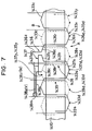
- FIG. 7 A portion of a winding diagram of the U-phase winding of three-phase-6-pole-18-slot stator winding 1420 is illustrated in Fig. 7.
- the U-phase winding is formed from a series connection of wave-wound coils 1433x illustrated by a solid line and wave-wound coil 1433y illustrated by a broken line.
- the series connection of wave-wound coils 1433x and the series connection of wave-wound coils 1433y are shifted electric angle ⁇ from each other.
- An end of the series connection of wave-wound coil 1433x is comprised of I-segment 1436.
- I-segment 1436 is comprised of projecting portion 1436s, in-slot portion 1436r, half-turn portion 1436c, and output lead wire portion 1436z.
- I-segment 1436 is formed of a straight conductor segment, which is inserted into the first slots S of the wave-wound coil 1433x. Then projecting portion 1436s is bent, and end 1436d of projecting portion 1435s is welded to end 1433d of the first U-segment 1433.
- Half-turn portion 1436c is bent to shift a half of the normal pitch of turn portion 1433c in the circumferential direction.
- Lead wire portion 1436z extends from one end of half turn portion 1436 over a prescribed electric angle in the circumferential direction at a prescribed distance from turn portion 1433c on the side of turn portion 1433c remote from stator core 1410. Lead wire portion 1436z further extends radially outward to connect to a connector (not shown) fixed to a wall of housing. Therefore, lead wire portion 1436z is axially disposed near turn portion 1433c of turn-side coil end group B. The other end of wave-wound coil 1433x is comprised of I-segment 1437.
- I-segment 1437 has projecting portion 1437s, in-slot portion 1437r, half-turn portion 1437c, and joint portion 1437z.
- I-segment 1437 is formed from a straight conductor segment. The straight conductor segment is inserted into the last one of slots S of the series connection of wave-wound coils 1433x and bent at the portion corresponding to projecting portion 1433s, so that end 1437d is welded to end 1433d of U-segment 1433 of wave-wound coil 1433x.
- Half-turn portion 1437c extends as long as a half of normal turn portion 1433c in the circumferential direction.
- Joint portion 1437z extends along a circumference around turn portions 1433c at a certain gap from turn portions 1433c over a necessary arc length.
- End 1437y is welded to end 1439y of half-turn portion 1439c of I-segment 1439, which is inserted into the first one of slots S of the series connection of wave-wound coils 1433y.
- I-segment 1439 is the same as I-segment 1437 except joint portion 1439y.
- Reference numeral 1439d is the end of projecting portion 1439s of I-segment 1439, which is welded to end 1433d of the first one of U-segments 1433 of the series connection of wave-wound coils 1433y.
- the other end of the series connection of wave-wound coils 1433y is I-segment 1438.
- I-segment 1438 has projecting portion 1438s, in-slot portion 1438r, half-turn portion 1438c, and neutral point portion 1438z.
- I-segment 1438 is formed of a straight conductor segment, which is inserted into the last one of slots S of the series connection of wave-wound coils 1433y. A portion corresponding to projection portion 1438s is bent, so that the end of projecting portion 1438s is welded to end 1433d of the last one of U-segments 1433.
- Half-turn portion 1438c extends in the circumferential direction as long as a half of normal turn portion 1433c.
- Neutral point portion 1438z of the U-phase winding extends in a circumference around turn portions 1433c at a distance from turn portions 1433c over a necessary arc length.
- Neutral point portions 1438z of I-segments of the V-phase and W-phase windings have the same structure as neutral point portion 1438z of I-segment 1438 of the U-phase winding. However, each neutral point portion 1438z extends with others in a bundle to be welded together at its end 1438m to form the neutral point.
- lead wire portions 1436z, joint portions 1437z, neutral point portions 1438z are extended along the side of coil-end group B or near the axially outer side of turn-portion-side coil ends 1433c.
- All the in-slot portions can be closely fitted to the inside wall of the slots via insulators or members that are equivalent to the insulators. Therefore, all the in-slot portions can be cooled by cooling water evenly and sufficiently via stator core 32 and front frame 42.
- the number of slots is more than three (corresponding to the number of phases) times as many as the number of the magnetic poles. For example, not 96 slots (that is three times as many as 32 poles) but 192 slots are provided for a 32-pole-three-phase generator; or 144 slots are provided for a 24-pole-three-phase generator.
- the extra-many-slot structure increases the contact area of the in-slot portions of conductor segments 33 with the slot inner walls via insulators, so that the heat dissipation of conductor segments can be more improved.
- the temperature of coil ends 35 and 36 becomes higher than other portions, contrary to the open type rotary electric machine.
- the radial thickness and the axial length of the coil ends of the stator winding formed of serially connected U-segments can be reduced much from a corresponding continuously-wound-wire type stator winding.
- the volume and average length (from the in-slot portions) of the coil ends can be reduced so that the temperature rise of the coil ends of conductor segments 33 can be drastically reduced.
- Heat of the coil ends 35 and 36 can be conducted to the in-slot portion much, thereby to suppress the temperature rise of the coil ends effectively.
- the distance between frame 4 and coil ends 35, 36 is arranged to be more than 2 mm to reduce eddy current loss of frame 4 caused by alternating magnetic fields. It is possible that coil ends 35 and 36 are bent radially inward to increase the above distance. Because conductor segments 33 are rigid enough to keep the distance unchanged, the shape of coil of coil ends 35 and 36 can be maintained unchanged. This can omit the insulation film coating of conductor segments 33.
- the conduction space factor can be increased more than 70 %.
- the generator-motor is supplied to start an engine with much larger amount of input current than output current generated by the same, temperature rise of the stator winding in a short time can be suppressed. Because, the volume of the stator winding relative to the stator core and the heat capacity thereof can be increased.
- the liquid-cooled rotary electric machine can be connected to the crankshaft via a belt or a chain as the conventional alternators. This rotary electric machine can be directly connected to the crankshaft or via a gear unit.
- This liquid-cooled vehicle rotary electric machine can be used for a generator or a motor.
- the structure of the rotor or the stator winding can be changed to different types of structure.
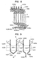
- a liquid-cooled vehicle rotary electric machine according to a second embodiment of the invention is described with reference to Fig. 10.
- This embodiment is characterized in that front coil ends 36 of the liquid-cooled vehicle rotary electric machine according to the first embodiment is molded with a heat-conductive resin 300 and brought in contact with the inner periphery and the inside end of front frame 42 of the same embodiment.
- each conductor segment 33 forming coil ends 36 is separated from others other at even gaps. Therefore, it is easy to fill fluid resin 300 into the gaps for the molding.
- the heat of coil ends 36 can be conducted through resin 300 to frame 4, so that the temperature of coil ends 36 can be lowered. Because resin 300 is not in direct contact with the cooling liquid, grounding or short-circuiting of the stator winding would not occur even if resin 300 cracks.
- FIG. 11 - 13 A liquid-cooled rotary electric machine according to a third embodiment of the invention is shown in Figs. 11 - 13.
- This embodiment is the same as the first embodiment except the following: the number of the conductor segments 33 in a slot is 4; there are two three-wave stator windings 1001 and 1002; and two converter 1003 and 1004 are provided. Because there are two circuit systems, the rotary electric machine becomes more reliable.
- FIG. 14 A liquid-cooled rotary electric machine according to a fourth embodiment of the invention is shown in Fig. 14.
- This embodiment is the same as the first embodiment embodiment except the following: two openings connected to cooling water passage 41 are formed at the inner periphery of frame 4 so that cooling water can directly contact the outer periphery of stator core 32.
- 0-ring 500 is disposed around two openings 410. Therefore, the cooling performance of the stator winding can be improved more.
- a liquid-cooled rotary electric machine according to a fifth embodiment of the invention is described hereafter.
- This embodiment is the same as the first embodiment except insulator 34, which is modified.
- Insulator 34 of this embodiment is made from fine powder of heat-conductive nonmagnetic insulation-resin such as polyimide-contained resin.
- heat transmission resistance which has been a fatal obstacle to practical use of the rotary electric machine having a liquid-cooled frame, can be drastically reduced without reducing effective magnetic flux or increasing iron loss or copper loss. This can reduce the temperature of the stator winding further.
Description
- The present invention relates to a liquid-cooled vehicle rotary electric machine driven by an internal combustion engine mounted in a vehicle, such as a passenger car or a truck.
- Recently, it has been considered to use a vehicle AC generator for engine-idling-stop system or an engine-torque assisting system.
- U.S. Patent 4,955,944 proposes a liquid-cooled rotary electric machine that has a liquid-cooled frame and a stator core fixedly fitted to the frame.
- JP-A-11-146606 proposes a liquid-cooled vehicle rotary electric machine in which coil ends of a stator winding are covered with insulation resin to be cooled by cooling liquid. It is necessary to cool the stator winding by cooling liquid because the coil ends is subject to a high temperature due to its poor heat conduction.
- JP-B2-2927288 proposes a vehicle AC generator in which each of a plurality of U-shaped conductor segments (hereinafter referred to as U-segment) is inserted into a pair of slots and each of the ends of the inserted U-segments is serially connected to another to form a stator winding.
- Furter, US Patent US 5,982,068 discloses a stator arrangement including a stator core and a multi-phase stator winding of an alternator for a vehivle. There, the stator winding is composed of a plurality of conductor segments having a pair of conductor members connected with one another to form a first coil-end group disposed on one axial end of the stator core so that first U-turn portions of the conductor segments are surrounded by second U-turn portions of the conductor segments and a second coil-end group disposed on the other axial end of said stator core so that ends of said conductor segments are connected to form lap windings.
- Moreover, the European patent application EP 0 302 118 A1 discloses a rotary machine, wherein an aramture core and a field core are fitted directly to a cylinder block so thta the armature core and the field core are cooled by a colling liquid flowing through a cooling passage inside this cylinder block. A heat pipe is fitted to the armature core or the field core is inserted into the cooliing passage inside the cylinder block so that the armature core or the field core can be cooled more efficiently. A bracket to which the armature core and the field core are fixed is fitted to the cylinder block, and a cooling liquid passage communicating with the cooling passage inside the cylinder block is formed in this bracket or a heat pipe which is partially inserted into the cooling passage is disposed on the bracket.
- As the engine idling speed has been decreasing, it has been demanded to increase electric power. On the other hand, an engine compartment has been made more compact, and a more compact vehicle AC generator has been required. The above demands have necessarily increased the maximum current or the current density of the stator winding of the generator and temperature thereof. In other words, cooling performance of the stator winding is one of decisive factors of the size of a rotary electric machine.
- In a generator-motor that has a motor-function to be used for an engine-idling stop system or an engine-torque assist system, it is necessary to supply much more input current to the stator winding thereof than the output current to generate by the stator winding. As a result, the stator winding of the generator-motor presents much more serious temperature-rise problems than ordinary generators.
- In order to improve cooling performance of conventional open-type air-cooled vehicle AC generator, it is possible to adopt the above liquid-cooled frame. It was found that the temperature of the stator of the rotary electric machine having the liquid-cooled frame does not become as low as the ordinary rotary electric machine, although the former has more complicated structure. This is one of major reasons why the rotary electric machine having the liquid-cooled frame has not been put into practical use.
- The other liquid-cooled vehicle rotary electric machine having multi-layered coil ends that are cooled by cooling liquid via a resinous insulator has also the following problems. It is very difficult to fill resinous material into gaps of the coil ends that are not evenly distributed. Therefore, the temperature of the conductors inside the coil ends becomes so high that the resinous material cracks due to a difference in thermal expansion between the resinous material and the conductors of the coil ends. As a result, cooling liquid (or water) may get into the inside of the coil ends through the cracks, causing short-circuiting or grounding.
- There is the highest heat-transmission resistance between portions of conductor segments inside the slots and the insulators. Because the stator winding of the conventional liquid-cooled rotary electric machine is formed of round-wire coils wound one after another by a winding machine, it is very difficult to increase the conduction space factor of the slot to a certain higher value or to reduce dead spaces from the slot.
- When the winding is wound by a winding machine in the manner described above, the coils overlap each other in a plurality of layers and swell in the radial direction. However, the number of conductors of the coil ends has to be limited because the spaces at opposite ends of the stator core are limited for the coil ends. This also obstructs to increase in the space factor.
- Because considerably large portions of the slots are occupied by the dead spaces, the temperature of the stator winding becomes much higher than the temperature of the insulators and the stator core although a liquid-cooled frame is provided.
- The present invention has been made in view of the above problems. Therefore, a main object of the invention is to provide a compact and powerful liquid-cooled rotary electric machine.
- A main feature of the invention is a rotary electric machine that includes a liquid-cooled frame in which liquid flows and a stator core that is fixedly fitted to the inner periphery of the frame. A stator winding is formed of a plurality of serially connected U-segments. The stator winding having the serially connected U-segments provides excellent cooling performance. As a result, a drastically smaller size-to-current ratio can be achieved.
- There is a heat transmission channel in the rotary electric machine having a liquid-cooled frame between the heat generating stator winding and the cooling liquid. Heat is transmitted through the channel from the stator winding (including resinous insulation coating), insulators disposed between the stator winding and surfaces of slots, a stator core, a frame and the cooling liquid.
- The U-segment has much larger cross-sectional area than any other round wire conductor. The U-segment also has a rectangular cross-section that is fitted to the cross-sectional shape of the slot with very small spaces being interposed.
- As the cross-sectional area is increased, the number of portions of the U-segment disposed in the slots (hereinafter referred to as the in-slot portions) can be reduced. The rectangular cross-section of the U-segment makes each in-slot portion thereof close contact with the inner wall of the slot via an insulator, thereby reducing the heat-transmission resistance.
- Because of a large conduction space factor of the slot, the stator winding at the rotary electric machine according to the invention has a large cross-sectional area, which provides a low resistance of the stator winding and low temperature thereof and a high current capacity.
- Because the space necessary for the coil-ends of the serially connected U-shaped conductor-segment type stator winding is small, the conduction space factor of the slot is not limited by the coil-end space, and the temperature of the stator winding can be reduced further.
- For example, the conduction space factor of the slot of a conventional winding type stator is less than 50 %. This is because the cross-sectional area cannot be increased due to difficulty in the winding process.
- If the cross-sectional area of the slot of the stator is the same, the heat capacity of the stator winding of the rotary electric machine according to the invention can be made much larger than the conventional rotary electric machine. This can suppress a temperature rise even if the stator winding is supplied with a large amount of current in a short time.
- Because the cross-sectional factor of the conductor segment increases, the rigidity thereof increases. The coil ends can be shaped evenly with distances between the inner periphery of the frame and the coil ends become even. Therefore, it is possible to reduce the diameter of the frame, so that the generator can be made compact.
- According to another feature of the invention, the rotary electric machine is enclosed liquid-tightly. Therefore, the stator winding becomes resistant to environmental severe conditions.
- According to another feature of the invention, each of the in-slot portions is closely fitted to one of the plurality of slot via an insulator. This prevents excessive temperature rise of a limited area of the in-slot portions.
- According to another feature of the invention, the number of the slots is larger than the product of the number of the magnetic poles and the number of the phase of the stator.
- Because the coil ends do not closely overlap one another in the radial direction, a high conduction space factor can be provided. Because the conductor segments do not overlap one another in the circumferential direction, they can closely contact the inner wall of the slots. Therefore, as the number of the slots increases, the inner surface area of the slots increases without decrease in the space factor or the contact area of the in-slot portions with the slot. Thus, an amount of the heat dissipation can be increased, and the temperature rise of the stator winding can be suppressed more effectively.
- According to another feature of the invention, each of the coil ends is separated from each other. Therefore, heat-conductive resinous material can be suitably filled in the gaps between the conductor segments of the coil ends.
- Further, the insulator material does not directly contact cooling water. Therefore, there would be no chance of short-circuiting or grounding even if it cracks.
- According to a further feature of the invention, the stator winding can be supplied with larger current at a motor mode than current generated at a generator mode, while suppressing the size increase and temperature rise of the stator winding.
- A generator-motor for a vehicle operates as a motor to start an engine or assist an engine to accelerate the vehicle. The maximum motor current becomes a number of times as much as the maximum output current when it operates as a generator. Such maximum motor current is supplied in a comparatively a short period of time. Therefore, it is very important to suppress temperature rise of a stator winding while the vehicle generator-motor is starting or assisting the engine, in such a short period of time.
- The above-stated serial U-shaped-conductor stator winding has a very high conduction space factor, very low heat resistance of the in-slot portions, and a large mass of the in-slot portions. Therefore, the stator winding can stand very large motor current in a short time.
- Other objects, features and characteristics of the present invention as well as the functions of related parts of the present invention will become clear from a study of the following detailed description, the appended claims and the drawings. In the drawings:
- Fig. 1 is a longitudinal cross-sectional view of a main portion of a liquid-cooled rotary electric machine according to a first embodiment of the invention;
- Fig. 2 is a radial cross-sectional view of the portion shown in Fig. 1;
- Fig. 3 is a radial cross-sectional view of a portion of the stator shown in Fig. 1;
- Fig. 4 is a fragmentary schematic diagram illustrating U-segments forming the stator winding shown in Fig. 1;
- Fig. 5 is a fragmentary perspective view illustrating a portion of the stator shown in Fig. 1;
- Fig. 6 is a fragmentary development view of the stator shown in Fig. 1 viewed from the center axis thereof in the radially outer direction;
- Fig. 7 is a fragmentary development view of the stator winding shown in Fig. 1;
- Fig. 8 is a fragmentary perspective view of the stator shown in Fig. 1;
- Fig. 9 is a schematic diagram illustrating U-segments that form the stator winding shown in Fig. 1;
- Fig. 10 is a fragmentary longitudinal cross-sectional view of a main portion of a liquid-cooled rotary electric machine according to a second embodiment of the invention;
- Fig. 11 is a fragmentary longitudinal cross-sectional view of a main portion of a liquid-cooled rotary electric machine according to a third embodiment of the invention;
- Fig. 12 is a fragmentary enlarged view of the stator shown in Fig. 11;
- Fig. 13 is a circuit diagram of the stator winding shown in Fig. 11; and
- Fig. 14 is a fragmentary longitudinal cross-sectional view of a main portion of a liquid-cooled rotary electric machine according to a fourth embodiment.
- Liquid-cooled vehicle rotary electric machines according to some preferred embodiments of the invention are described with reference to the appended drawings.
- A liquid-cooled rotary electric machine according to a first embodiment of the invention is described with reference to Figs. 1 and 2.
- Liquid-cooled vehicle
rotary machine 1 includesstator 2 that operates as an armature,rotor 3 that provides magnetic fields, andframe 4 that supportsstator 2 androtor 3. -
Rotor 3 is fixedly fixed toshaft 6, a pair of pole cores 7 having a plurality ofclaw poles 73,connection ring 71 that connects the pair of pole cores 7,field coil 31, andstationary yoke 72.Shaft 6 is connected with an engine crankshaft, andfield coil 31 makes the pair of pole cores 7 generate magnetic field. -
Field coil 31 is fitted to an annular groove that is formed in the outer periphery ofstationary yoke 72 to open radially outward.Stationary yoke 72 is closely fixed to the rear end offrame 4 at the front surface thereof. The magnetic fluxes flow fromfield coil 3, throughstationary yoke 72, radially inner portion of pole core 7, a half of allclaw poles 73 of pole cores 7,stator core 32 ofstator 2, the other half ofclaw poles 73, andstationary core 72, back tofield coil 3. -
Frame 4 includesfront frame 42 andrear frame 43.Front frame 42 has coolingwater passage 41 therein,stationary yoke 72 on the rear surface thereof andstator 2 on the inner periphery thereof.Rear frame 43 closes the rear opening of thefront frame 42. -
Stator 2 hasstator core 32 and a stator winding. The stator winding is mainly formed of a plurality of serially connected U-segments (hereinafter referred to as the U-segments) 33 andinsulators 34 that insulate the plurality of U-segments 33 fromstator core 32. Each of U-segments 33 has a rectangular cross-section.Stator core 32 is formed of laminated electro-magnetic iron sheets and has a plurality of slots 5 formed at the inner periphery thereof at equal intervals. A leg of one of U-segments 33 is inserted into the radially outside layer of slot 5 and another leg of another U-segment 33 is inserted into the radially inside layer of the same slot. - Each U-segment 33 has a pair of legs to be inserted into different slots and turn
portion 33c connecting the pair of legs.Turn portion 33c projects rearward from the rear end ofstator core 32. Portions of the pair of legs disposed in slots 5 are referred to as in-slot portions, and portions of the pair of the legs projecting forward from the front end ofstator core 32 are referred to as projecting portions. As shown in Fig. 2, each slot 5 accommodates in-slot portion 33a at the inside layer thereof and in-slot portion 33b at the outside layer. The ends of the projecting portions are bent to extend in opposite circumferential directions to be paired with another so that each pair is welded to form joint 33d. Accordingly, turnportions 33c form rear coil ends 35 and the projecting portions form front coil ends 36. - There is a prescribed distance or space between
adjacent conductor segments 33. The stator winding is formed of star-connected X, Y, and Z-phase windings. The open ends of the windings are connected to converter 5, which is connected to a battery. - The stator winding is described in more detail with reference to Figs. 3 - 9. The portions shown in Figs. 3 - 9 are denoted separately from those shown in Figs. 1 and 2.
- Stator winding 1420 is a star-connected three-phase winding, which is formed of a plurality of U-segments 1433 or I-shaped conductor segments (hereinafter referred to as I-segment) whose ends are serially welded at an end of
stator core 1410. - Each U-segment 1433 is formed of a flat wire coated with an insulation film, and inserted into one of two radial layers of a slot S. As shown in Fig. 4, U-segment 1433 has turn
portion 1433c forming a coil end, a pair of in-slot portions 1433r, and a pair of projectingportions 1433s that respectively extend from in-slot portions 1433r. One of the pair of in-slot portions is inserted into a different slot that is π radian in electric angle spaced apart from the other. Each pair of projectingportions 1433s forms coil ends. The ends 1433d of projectingportions 1433s form joint portions. - The center of
turn portion 1433c is located atsummit 1433p of one of the projecting coil ends remote from the stator core.Turn portion 1433c extends in an axial direction and opposite circumferential directions fromsummit 1433p so that one side thereof extends by 0.5π radian in electric angle in a circumferential direction. Projectingportion 1433s is also bent to extend in a circumferential direction by 0.5π radian in electric angle. -
U-segment 1433 is also bent in the radial direction atsummit 1433p so that a half of U-segment 1433 including one side ofturn portion 1433c, in-slot portion 1433r and projectingportion 1433s can shift in the radial direction by an approximately radial length ofconductor segment 1433 from the other half including the other side ofturn portion 1433c, in-slot portion 1433r and projectingportion 1433s. - Each U-segment 1433 is inserted from one end of
stator core 1410 into slots S. After pairs of projectingportions 1433c of U-segments projecting from the other end are bent in the circumferential directions, ends 1433d of the projectingportions 1433s are paired and welded to form wave-wound star-connected three-phase stator winding 1420. As shown in Fig. 5, oneend 1433d of projectingportion 1433s projecting from the radially outer layer of one of slots S and anotherend 1433d of projectingportion 1433s projecting from the radially inner layer of another slot S are welded. In Fig. 4, solid lines illustrate projectingportions 1433s before bent, and two-dot-chain lines illustrate the same after bent.Turn portions 1433c are disposed on an end ofstator core 1410, and projectingportions 1433s are disposed on the other end. - In Fig. 6,
reference numeral 1434 indicates an insulator.Insulation sheets 1660 and 1670 are omitted from this diagram. - A portion of a winding diagram of the U-phase winding of three-phase-6-pole-18-slot stator winding 1420 is illustrated in Fig. 7.
- The U-phase winding is formed from a series connection of wave-
wound coils 1433x illustrated by a solid line and wave-wound coil 1433y illustrated by a broken line. The series connection of wave-wound coils 1433x and the series connection of wave-wound coils 1433y are shifted electric angle π from each other. An end of the series connection of wave-wound coil 1433x is comprised of I-segment 1436. - I-segment 1436, as shown in Fig. 9, is comprised of projecting
portion 1436s, in-slot portion 1436r, half-turn portion 1436c, and outputlead wire portion 1436z. I-segment 1436 is formed of a straight conductor segment, which is inserted into the first slots S of the wave-wound coil 1433x. Then projectingportion 1436s is bent, and end 1436d of projecting portion 1435s is welded to end 1433d of the first U-segment 1433. Half-turn portion 1436c is bent to shift a half of the normal pitch ofturn portion 1433c in the circumferential direction.Lead wire portion 1436z extends from one end of half turn portion 1436 over a prescribed electric angle in the circumferential direction at a prescribed distance fromturn portion 1433c on the side ofturn portion 1433c remote fromstator core 1410.Lead wire portion 1436z further extends radially outward to connect to a connector (not shown) fixed to a wall of housing. Therefore,lead wire portion 1436z is axially disposed nearturn portion 1433c of turn-side coil end group B. The other end of wave-wound coil 1433x is comprised of I-segment 1437. - I-
segment 1437 has projectingportion 1437s, in-slot portion 1437r, half-turn portion 1437c, andjoint portion 1437z. I-segment 1437 is formed from a straight conductor segment. The straight conductor segment is inserted into the last one of slots S of the series connection of wave-wound coils 1433x and bent at the portion corresponding to projectingportion 1433s, so thatend 1437d is welded to end 1433d ofU-segment 1433 of wave-wound coil 1433x. - Half-
turn portion 1437c extends as long as a half ofnormal turn portion 1433c in the circumferential direction.Joint portion 1437z extends along a circumference aroundturn portions 1433c at a certain gap fromturn portions 1433c over a necessary arc length.End 1437y is welded to end 1439y of half-turn portion 1439c of I-segment 1439, which is inserted into the first one of slots S of the series connection of wave-wound coils 1433y. I-segment 1439 is the same as I-segment 1437 exceptjoint portion 1439y.Reference numeral 1439d is the end of projecting portion 1439s of I-segment 1439, which is welded to end 1433d of the first one ofU-segments 1433 of the series connection of wave-wound coils 1433y. The other end of the series connection of wave-wound coils 1433y is I-segment 1438. - I-
segment 1438 has projectingportion 1438s, in-slot portion 1438r, half-turn portion 1438c, andneutral point portion 1438z. I-segment 1438 is formed of a straight conductor segment, which is inserted into the last one of slots S of the series connection of wave-wound coils 1433y. A portion corresponding toprojection portion 1438s is bent, so that the end of projectingportion 1438s is welded to end 1433d of the last one ofU-segments 1433. Half-turn portion 1438c extends in the circumferential direction as long as a half ofnormal turn portion 1433c.Neutral point portion 1438z of the U-phase winding extends in a circumference aroundturn portions 1433c at a distance fromturn portions 1433c over a necessary arc length. -
Neutral point portions 1438z of I-segments of the V-phase and W-phase windings have the same structure asneutral point portion 1438z of I-segment 1438 of the U-phase winding. However, eachneutral point portion 1438z extends with others in a bundle to be welded together at itsend 1438m to form the neutral point. - In this embodiment,
lead wire portions 1436z,joint portions 1437z,neutral point portions 1438z are extended along the side of coil-end group B or near the axially outer side of turn-portion-side coil ends 1433c. - Thus the following effects of the invention can be provided.
- All the in-slot portions can be closely fitted to the inside wall of the slots via insulators or members that are equivalent to the insulators. Therefore, all the in-slot portions can be cooled by cooling water evenly and sufficiently via
stator core 32 andfront frame 42. - The number of slots is more than three (corresponding to the number of phases) times as many as the number of the magnetic poles. For example, not 96 slots (that is three times as many as 32 poles) but 192 slots are provided for a 32-pole-three-phase generator; or 144 slots are provided for a 24-pole-three-phase generator. The extra-many-slot structure increases the contact area of the in-slot portions of
conductor segments 33 with the slot inner walls via insulators, so that the heat dissipation of conductor segments can be more improved. - The temperature of coil ends 35 and 36 becomes higher than other portions, contrary to the open type rotary electric machine.
- The radial thickness and the axial length of the coil ends of the stator winding formed of serially connected U-segments can be reduced much from a corresponding continuously-wound-wire type stator winding. The volume and average length (from the in-slot portions) of the coil ends can be reduced so that the temperature rise of the coil ends of
conductor segments 33 can be drastically reduced. - Heat of the coil ends 35 and 36 can be conducted to the in-slot portion much, thereby to suppress the temperature rise of the coil ends effectively.
- Because a sealed type rotary electric machine can be provided without minding temperature rise of the stator winding, a much stronger rotary electric machine against the environmental conditions than conventional rotary electric machine can be provided.
- The distance between
frame 4 and coil ends 35, 36 is arranged to be more than 2 mm to reduce eddy current loss offrame 4 caused by alternating magnetic fields. It is possible that coil ends 35 and 36 are bent radially inward to increase the above distance. Becauseconductor segments 33 are rigid enough to keep the distance unchanged, the shape of coil of coil ends 35 and 36 can be maintained unchanged. This can omit the insulation film coating ofconductor segments 33. - The conduction space factor can be increased more than 70 %.
- Since two or four U-segments are radially aligned and inserted into each slot, all the in-slot portions are fitted to the inner walls of the slots via insulators. In addition, at least other two or more surfaces of the U-segment can be fitted to the inner walls of the slots of the heat dissipating stator core via insulators.
- None of the in-slot portions is excessively heated to increase the temperature thereof higher than the heat resistant temperature of the insulation coating of the stator winding.
- If the generator-motor is supplied to start an engine with much larger amount of input current than output current generated by the same, temperature rise of the stator winding in a short time can be suppressed. Because, the volume of the stator winding relative to the stator core and the heat capacity thereof can be increased.
- The liquid-cooled rotary electric machine can be connected to the crankshaft via a belt or a chain as the conventional alternators. This rotary electric machine can be directly connected to the crankshaft or via a gear unit.
- This liquid-cooled vehicle rotary electric machine can be used for a generator or a motor. The structure of the rotor or the stator winding can be changed to different types of structure.
- A liquid-cooled vehicle rotary electric machine according to a second embodiment of the invention is described with reference to Fig. 10.
- This embodiment is characterized in that front coil ends 36 of the liquid-cooled vehicle rotary electric machine according to the first embodiment is molded with a heat-
conductive resin 300 and brought in contact with the inner periphery and the inside end offront frame 42 of the same embodiment. - In other words, each
conductor segment 33 forming coil ends 36 is separated from others other at even gaps. Therefore, it is easy to fillfluid resin 300 into the gaps for the molding. - In addition, the heat of coil ends 36 can be conducted through
resin 300 toframe 4, so that the temperature of coil ends 36 can be lowered. Becauseresin 300 is not in direct contact with the cooling liquid, grounding or short-circuiting of the stator winding would not occur even ifresin 300 cracks. - It is also possible to mold coil ends 35 with the same resin. A liquid-cooled rotary electric machine according to a third embodiment of the invention is shown in Figs. 11 - 13.
- This embodiment is the same as the first embodiment except the following: the number of the
conductor segments 33 in a slot is 4; there are two three-wave stator windings converter - A liquid-cooled rotary electric machine according to a fourth embodiment of the invention is shown in Fig. 14.
- This embodiment is the same as the first embodiment embodiment except the following: two openings connected to cooling
water passage 41 are formed at the inner periphery offrame 4 so that cooling water can directly contact the outer periphery ofstator core 32. 0-ring 500 is disposed around twoopenings 410. Therefore, the cooling performance of the stator winding can be improved more. - A liquid-cooled rotary electric machine according to a fifth embodiment of the invention is described hereafter.
- This embodiment is the same as the first embodiment except
insulator 34, which is modified. -
Insulator 34 of this embodiment is made from fine powder of heat-conductive nonmagnetic insulation-resin such as polyimide-contained resin. - Thus, heat transmission resistance, which has been a fatal obstacle to practical use of the rotary electric machine having a liquid-cooled frame, can be drastically reduced without reducing effective magnetic flux or increasing iron loss or copper loss. This can reduce the temperature of the stator winding further.
- In the foregoing description of the present invention, the invention has been disclosed with reference to specific embodiments thereof. It will, however, be evident that various modifications and changes may be made to the specific embodiments of the present invention without departing from the broader scope of the invention as set forth in the appended claims. Accordingly, the description of the present invention is to be regarded in an illustrative, rather than a restrictive, sense.
Claims (6)
- A liquid-cooled vehicle rotary electric machine operable in a motor mode or a generator mode comprising:a frame (4) having an inner periphery and a liquid passage (41);a stator core (32) having an outer periphery fixedly fitted to said inner periphery of said frame (4) and a plurality of slots (S);a multi-phase stator winding (1420) accomodated in said plurality of slots (S);a rotor (3) rotatably supported by said frame (4) and disposed inside said stator core (32) so as to electromagnetically connect said stator core (32);characterized in thatsaid stator winding (1420) comprises a plurality of U-shaped conductor segments (33, 1433) each of which has a pair of legs (1433r), andeach of said legs (1433r) is inserted in a slot from one end of said stator core (32) and connected to be paired to another leg at a portion extending from the other end of said stator core (32),wherein said rotor (3) has a plurality of different magnetic poles (7, 73) alternately disposed at prescribed intervals in the circumferential direction thereof and, in order to increase the contact area of the in-slot portions of the conductor segments with the slot inner walls, so that the heat dissipation of the conductor segments can be improved, the number of said slots (S) is larger than the product of the number of said magnetic poles (7, 73) and the number of the phases of said stator winding (1420).
- The liquid-cooled rotary electric machine as claimed in claim 1 having a space factor more than 55 %, wherein
each of said U-shaped conductor segments (33, 1433) comprises a flat wire. - The liquid-cooled vehicle rotary electric machine as claimed in claim 1, wherein
said stator core (32) and said stator winding (1420) are liquid-tightly enclosed by said frame (4). - The liquid-cooled rotary electric machine as claimed in claim 1, wherein
each of said legs (1433r) inserted in said plurality of slots (S) is closely fitted to one of said plurality of slot via an insulator (1434). - The liquid-cooled rotary electric machine as claimed in claim 1, wherein
said stator winding (1420) has a plurality of coil ends formed of said U-shaped conductor segments (33, 1433) separated from each other,
each of said coil ends is covered by and filled with insulating material (300), and
said insulating material (300) is closely fitted to said frame (4). - The liquid-cooled rotary electric machine as claimed in claim 1, wherein
said stator winding (1420) is supplied with larger current at said motor mode than current generated at said generator mode.
Applications Claiming Priority (2)
| Application Number | Priority Date | Filing Date | Title |
|---|---|---|---|
| JP34055899A JP2001161050A (en) | 1999-11-30 | 1999-11-30 | Liquid-cooled dynamoelectric machine for vehicle |
| JP34055899 | 1999-11-30 |
Publications (3)
| Publication Number | Publication Date |
|---|---|
| EP1107433A2 EP1107433A2 (en) | 2001-06-13 |
| EP1107433A3 EP1107433A3 (en) | 2002-05-15 |
| EP1107433B1 true EP1107433B1 (en) | 2006-06-14 |
Family
ID=18338154
Family Applications (1)
| Application Number | Title | Priority Date | Filing Date |
|---|---|---|---|
| EP00126002A Expired - Lifetime EP1107433B1 (en) | 1999-11-30 | 2000-11-28 | Liquid-cooled vehicle rotary electric machine |
Country Status (4)
| Country | Link |
|---|---|
| US (1) | US6700236B2 (en) |
| EP (1) | EP1107433B1 (en) |
| JP (1) | JP2001161050A (en) |
| DE (1) | DE60028703T2 (en) |
Cited By (1)
| Publication number | Priority date | Publication date | Assignee | Title |
|---|---|---|---|---|
| DE102020214898A1 (en) | 2020-11-26 | 2022-06-02 | Valeo Siemens Eautomotive Germany Gmbh | Stator laminated core for a stator of an electric machine, stator for an electric machine and electric machine for driving a vehicle |
Families Citing this family (46)
| Publication number | Priority date | Publication date | Assignee | Title |
|---|---|---|---|---|
| JP4461590B2 (en) * | 2000-08-25 | 2010-05-12 | 株式会社デンソー | Vehicle alternator |
| FR2819117B1 (en) * | 2000-12-21 | 2004-10-29 | Valeo Equip Electr Moteur | ALTERNATOR WITH CONDUCTIVE ELEMENTS FOR A MOTOR VEHICLE |
| GB0206645D0 (en) * | 2002-03-21 | 2002-05-01 | Rolls Royce Plc | Improvements in or relating to magnetic coils for electrical machines |
| DE10342755B4 (en) | 2002-09-17 | 2018-06-14 | Denso Corporation | Rotating high voltage electric machine |
| US7701106B2 (en) | 2003-06-21 | 2010-04-20 | Oilfield Equipment Development Center Limited | Electric submersible pumps |
| GB0314553D0 (en) | 2003-06-21 | 2003-07-30 | Weatherford Lamb | Electric submersible pumps |
| GB0314550D0 (en) | 2003-06-21 | 2003-07-30 | Weatherford Lamb | Electric submersible pumps |
| GB0314555D0 (en) * | 2003-06-21 | 2003-07-30 | Weatherford Lamb | Electric submersible pumps |
| WO2005089257A2 (en) * | 2004-03-16 | 2005-09-29 | Tecogen, Inc. | Engine driven power inverter system with cogeneration |
| GB0426585D0 (en) | 2004-12-06 | 2005-01-05 | Weatherford Lamb | Electrical connector and socket assemblies |
| JP2006211810A (en) * | 2005-01-27 | 2006-08-10 | Denso Corp | Segment connection type rotary electric machine |
| US7495363B2 (en) * | 2005-12-21 | 2009-02-24 | Raytheon Company | Maximum conductor motor and method of making same |
| JPWO2008020471A1 (en) * | 2006-08-15 | 2010-01-07 | 株式会社日立製作所 | Rotating electric machine |
| US7633194B2 (en) * | 2006-10-26 | 2009-12-15 | Gm Global Technology Operations, Inc. | Apparatus for cooling stator lamination stacks of electrical machines |
| JP2009011116A (en) | 2007-06-29 | 2009-01-15 | Hitachi Ltd | Rotation electric machine having a wave winding coil with cranked crossover conductor, distributed winding stator, and method and apparatus for forming same |
| US7804215B2 (en) * | 2008-09-30 | 2010-09-28 | General Electric Company | Integrated cooling concept for magnetically geared machine |
| US8080909B2 (en) * | 2009-05-19 | 2011-12-20 | Ford Global Technologies, Llc | Cooling system and method for an electric motor |
| US8525375B2 (en) * | 2010-03-23 | 2013-09-03 | Hamilton Sundstrand Corporation | Cooling arrangement for end turns and stator in an electric machine |
| JP5663191B2 (en) * | 2010-04-27 | 2015-02-04 | 本田技研工業株式会社 | Motor stator |
| SE534838C2 (en) * | 2010-05-21 | 2012-01-17 | Bae Systems Haegglunds Ab | Electric motor cooling device |
| JP5691266B2 (en) * | 2010-07-01 | 2015-04-01 | トヨタ自動車株式会社 | Rotating electric machine stator |
| IT1401829B1 (en) * | 2010-09-29 | 2013-08-28 | Magneti Marelli Spa | ELECTRIC MACHINE PRESENTING A STATIC ROLL WITH RIGID BARS AND ITS CONSTRUCTION METHOD |
| DE102010062338A1 (en) * | 2010-12-02 | 2012-06-06 | Robert Bosch Gmbh | Method and device for operating a separately excited electrical machine |
| US20130002067A1 (en) * | 2011-06-30 | 2013-01-03 | Bradfield Michael D | Electric Machine Module Cooling System and Method |
| JP5926532B2 (en) * | 2011-10-27 | 2016-05-25 | コベルコ建機株式会社 | Electric motor |
| US20130221773A1 (en) * | 2012-02-23 | 2013-08-29 | Bradley D. Chamberlin | Electric machine module |
| US10069375B2 (en) * | 2012-05-02 | 2018-09-04 | Borgwarner Inc. | Electric machine module cooling system and method |
| FR2995833B1 (en) | 2012-09-25 | 2015-08-07 | Valeo Equip Electr Moteur | HYBRID MODULE FOR A MOTOR VEHICLE TRANSMISSION ASSEMBLY |
| EP2900506B1 (en) | 2012-09-25 | 2018-08-15 | Valeo Equipements Electriques Moteur | Transmission assembly for a motor vehicle |
| FR2995832B1 (en) | 2012-09-25 | 2014-09-05 | Valeo Equip Electr Moteur | TRANSMISSION ASSEMBLY HAVING A ROTOR HUB WITH ANTI-DUST FLASK |
| CN104703828B (en) | 2012-09-25 | 2017-12-01 | 法雷奥电机设备公司 | The device between motor and reaction plate with dust ring for motor vehicle driven by mixed power |
| FR2995834B1 (en) | 2012-09-25 | 2014-09-05 | Valeo Equip Electr Moteur | TRANSMISSION ASSEMBLY FOR MOTOR VEHICLE |
| WO2015040285A1 (en) | 2013-09-20 | 2015-03-26 | Valeo Equipements Electriques Moteur | Hybrid module for motor vehicle transmission assembly |
| WO2015040283A1 (en) | 2013-09-20 | 2015-03-26 | Valeo Equipements Electriques Moteur | Transmission assembly for motor vehicle |
| WO2015040284A1 (en) | 2013-09-20 | 2015-03-26 | Valeo Equipements Electriques Moteur | Transmission assembly for motor vehicle |
| US11245299B2 (en) * | 2016-03-31 | 2022-02-08 | Hitachi Astemo, Ltd. | Stator for rotary electric machine and rotary electric machine using same |
| US11843334B2 (en) | 2017-07-13 | 2023-12-12 | Denso Corporation | Rotating electrical machine |
| JP6977555B2 (en) | 2017-07-21 | 2021-12-08 | 株式会社デンソー | Rotating machine |
| CN113972807B (en) | 2017-07-21 | 2023-10-27 | 株式会社电装 | Rotary electric machine |
| CN111566904B (en) | 2017-12-28 | 2023-04-28 | 株式会社电装 | Rotary electric machine |
| JP7006541B2 (en) | 2017-12-28 | 2022-01-24 | 株式会社デンソー | Rotating machine |
| JP6927186B2 (en) * | 2017-12-28 | 2021-08-25 | 株式会社デンソー | Rotating machine |
| JP7434716B2 (en) * | 2019-03-11 | 2024-02-21 | 株式会社デンソー | electric drive device |
| US10965183B2 (en) | 2019-06-14 | 2021-03-30 | Honeywell International Inc. | Integrated traction drive system |
| US11894756B2 (en) * | 2021-01-25 | 2024-02-06 | Honeywell International Inc. | Systems and methods for electric propulsion systems for electric engines |
| US11936327B2 (en) | 2021-06-23 | 2024-03-19 | Tecogen Inc. | Hybrid power system with electric generator and auxiliary power source |
Citations (2)
| Publication number | Priority date | Publication date | Assignee | Title |
|---|---|---|---|---|
| EP0874444A1 (en) * | 1997-04-22 | 1998-10-28 | General Motors Corporation | Heat conducting means for electric motor or generator |
| EP0881742A2 (en) * | 1997-05-26 | 1998-12-02 | Denso Corporation | AC generator for vehicles |
Family Cites Families (23)
| Publication number | Priority date | Publication date | Assignee | Title |
|---|---|---|---|---|
| US2862120A (en) * | 1957-07-02 | 1958-11-25 | Onsrud Machine Works Inc | Fluid-cooled motor housing |
| US4739204A (en) * | 1986-01-30 | 1988-04-19 | Mitsubishi Denki Kabushiki Kaisha | Liquid cooled a.c. vehicle generator |
| US4980588A (en) * | 1986-02-14 | 1990-12-25 | Mitsubishi Denki Kabushiki Kaisha | Water-cooled vehicle generator |
| JPS62260544A (en) * | 1986-04-07 | 1987-11-12 | Mitsubishi Electric Corp | Ac generator for vehicle |
| EP0302118B1 (en) * | 1987-02-10 | 1993-08-04 | Mitsubishi Denki Kabushiki Kaisha | Rotary machine |
| JPS63257435A (en) * | 1987-04-13 | 1988-10-25 | Mitsubishi Electric Corp | Ac generator for rolling stock |
| JPH0810974B2 (en) * | 1988-04-25 | 1996-01-31 | 三菱電機株式会社 | Vehicle alternator |
| EP0816147A3 (en) * | 1996-07-02 | 2000-03-08 | Denso Corporation | Rotating apparatus and heating apparatus, for vehicle |
| DE19637671C1 (en) * | 1996-09-16 | 1998-02-12 | Clouth Gummiwerke Ag | Dynamoelectric machine with a cooling jacket through which liquid flows |
| JP3407643B2 (en) * | 1997-05-26 | 2003-05-19 | 株式会社デンソー | AC generator for vehicles |
| CA2238504C (en) * | 1997-05-26 | 2001-03-13 | Atsushi Umeda | Stator arrangement of alternator for vehicle |
| WO1998054822A1 (en) | 1997-05-26 | 1998-12-03 | Denso Corporation | Ac generator for vehicle |
| US5965965A (en) * | 1997-05-26 | 1999-10-12 | Denso Corporation | Stator winding arrangement of alternator for vehicle |
| US6137201A (en) * | 1997-05-26 | 2000-10-24 | Denso Corporation | AC generator for vehicles |
| BR9801695B1 (en) * | 1997-05-26 | 2009-08-11 | rotary electric machine. | |
| US5997261A (en) * | 1997-10-31 | 1999-12-07 | Siemens Canada Limited | Pump motor having fluid cooling system |
| JPH11146606A (en) | 1997-11-07 | 1999-05-28 | Hitachi Ltd | Water-cooled alternator |
| DE19809966C1 (en) * | 1998-03-07 | 1999-09-16 | Daimler Chrysler Ag | Liquid cooled generator |
| EP0961386B1 (en) * | 1998-05-25 | 2003-01-02 | Denso Corporation | Stator of ac generator for vehicle |
| US5939808A (en) * | 1998-06-03 | 1999-08-17 | Adames; Fermin | Electric motor housing with integrated heat removal facilities |
| JP3877894B2 (en) * | 1999-01-13 | 2007-02-07 | 三菱電機株式会社 | Brushless AC generator for vehicles |
| US6300693B1 (en) * | 1999-03-05 | 2001-10-09 | Emerson Electric Co. | Electric motor cooling jacket assembly and method of manufacture |
| US6313556B1 (en) * | 1999-09-30 | 2001-11-06 | Reliance Electric Technologies, Llc | Superconducting electromechanical rotating device having a liquid-cooled, potted, one layer stator winding |
-
1999
- 1999-11-30 JP JP34055899A patent/JP2001161050A/en active Pending
-
2000
- 2000-11-28 EP EP00126002A patent/EP1107433B1/en not_active Expired - Lifetime
- 2000-11-28 DE DE60028703T patent/DE60028703T2/en not_active Expired - Lifetime
- 2000-11-29 US US09/725,081 patent/US6700236B2/en not_active Expired - Lifetime
Patent Citations (2)
| Publication number | Priority date | Publication date | Assignee | Title |
|---|---|---|---|---|
| EP0874444A1 (en) * | 1997-04-22 | 1998-10-28 | General Motors Corporation | Heat conducting means for electric motor or generator |
| EP0881742A2 (en) * | 1997-05-26 | 1998-12-02 | Denso Corporation | AC generator for vehicles |
Cited By (1)
| Publication number | Priority date | Publication date | Assignee | Title |
|---|---|---|---|---|
| DE102020214898A1 (en) | 2020-11-26 | 2022-06-02 | Valeo Siemens Eautomotive Germany Gmbh | Stator laminated core for a stator of an electric machine, stator for an electric machine and electric machine for driving a vehicle |
Also Published As
| Publication number | Publication date |
|---|---|
| EP1107433A3 (en) | 2002-05-15 |
| US20010002093A1 (en) | 2001-05-31 |
| DE60028703T2 (en) | 2007-05-24 |
| EP1107433A2 (en) | 2001-06-13 |
| DE60028703D1 (en) | 2006-07-27 |
| US6700236B2 (en) | 2004-03-02 |
| JP2001161050A (en) | 2001-06-12 |
Similar Documents
| Publication | Publication Date | Title |
|---|---|---|
| EP1107433B1 (en) | Liquid-cooled vehicle rotary electric machine | |
| US6552463B2 (en) | Dynamo-electric machine having winding phase groups of series-connected windings connected in parallel | |
| US5977679A (en) | Pole-phase modulated toroidal winding for an induction machine | |
| US6498413B2 (en) | Alternator, stator winding assembly therefor, and method of manufacture for the stator winding assembly | |
| US6498414B2 (en) | Stator of dynamo-electric machine | |
| US8203240B2 (en) | Liquid cooled rotating electrical machine | |
| US6414410B1 (en) | Rotary electric machine having reduced winding | |
| US6809441B2 (en) | Cooling of electrical machines | |
| JP2004166316A (en) | Segment conductor joint type armature and alternator provided therewith | |
| US6366000B1 (en) | Alternator | |
| JP6777760B2 (en) | Stator for rotary electric machine and rotary electric machine | |
| JP6793257B2 (en) | Stator of rotary electric machine and rotary electric machine | |
| US11764629B2 (en) | In-slot cooling system for an electric machine with hairpin windings | |
| JP2010514406A (en) | Stator for multi-phase rotating electrical machine, multi-phase rotating electrical machine having the stator, and method for manufacturing the stator | |
| JP2003158840A (en) | Stator for rotating electric machine for vehicle | |
| US20020017823A1 (en) | Alternator | |
| WO2020159821A1 (en) | Distributed stator winding having parallel paths with crossing end loops | |
| JP2008312324A (en) | Cooling structure for stator | |
| JP2004343877A (en) | Coil for rotary electric machine | |
| JP2007318902A (en) | Ac generator | |
| JP7030961B2 (en) | Stator and rotary machine | |
| JP4186316B2 (en) | AC generator for vehicles | |
| JP3624897B2 (en) | Coil feeding structure of synchronous motor | |
| EP1109294B1 (en) | Alternator | |
| JP7250214B2 (en) | Stator and rotating electrical machine |
Legal Events
| Date | Code | Title | Description |
|---|---|---|---|
| PUAI | Public reference made under article 153(3) epc to a published international application that has entered the european phase |
Free format text: ORIGINAL CODE: 0009012 |
|
| AK | Designated contracting states |
Kind code of ref document: A2 Designated state(s): AT BE CH CY DE DK ES FI FR GB GR IE IT LI LU MC NL PT SE TR |
|
| AX | Request for extension of the european patent |
Free format text: AL;LT;LV;MK;RO;SI |
|
| PUAL | Search report despatched |
Free format text: ORIGINAL CODE: 0009013 |
|
| AK | Designated contracting states |
Kind code of ref document: A3 Designated state(s): AT BE CH CY DE DK ES FI FR GB GR IE IT LI LU MC NL PT SE TR |
|
| AX | Request for extension of the european patent |
Free format text: AL;LT;LV;MK;RO;SI |
|
| 17P | Request for examination filed |
Effective date: 20020624 |
|
| AKX | Designation fees paid |
Designated state(s): DE FR GB |
|
| 17Q | First examination report despatched |
Effective date: 20040123 |
|
| GRAP | Despatch of communication of intention to grant a patent |
Free format text: ORIGINAL CODE: EPIDOSNIGR1 |
|
| GRAS | Grant fee paid |
Free format text: ORIGINAL CODE: EPIDOSNIGR3 |
|
| GRAA | (expected) grant |
Free format text: ORIGINAL CODE: 0009210 |
|
| AK | Designated contracting states |
Kind code of ref document: B1 Designated state(s): DE FR GB |
|
| REG | Reference to a national code |
Ref country code: GB Ref legal event code: FG4D |
|
| REF | Corresponds to: |
Ref document number: 60028703 Country of ref document: DE Date of ref document: 20060727 Kind code of ref document: P |
|
| ET | Fr: translation filed | ||
| PLBE | No opposition filed within time limit |
Free format text: ORIGINAL CODE: 0009261 |
|
| STAA | Information on the status of an ep patent application or granted ep patent |
Free format text: STATUS: NO OPPOSITION FILED WITHIN TIME LIMIT |
|
| 26N | No opposition filed |
Effective date: 20070315 |
|
| REG | Reference to a national code |
Ref country code: FR Ref legal event code: PLFP Year of fee payment: 16 |
|
| REG | Reference to a national code |
Ref country code: FR Ref legal event code: PLFP Year of fee payment: 17 |
|
| REG | Reference to a national code |
Ref country code: FR Ref legal event code: PLFP Year of fee payment: 18 |
|
| PGFP | Annual fee paid to national office [announced via postgrant information from national office to epo] |
Ref country code: FR Payment date: 20171121 Year of fee payment: 18 Ref country code: DE Payment date: 20171121 Year of fee payment: 18 |
|
| PGFP | Annual fee paid to national office [announced via postgrant information from national office to epo] |
Ref country code: GB Payment date: 20171123 Year of fee payment: 18 |
|
| REG | Reference to a national code |
Ref country code: DE Ref legal event code: R119 Ref document number: 60028703 Country of ref document: DE |
|
| GBPC | Gb: european patent ceased through non-payment of renewal fee |
Effective date: 20181128 |
|
| PG25 | Lapsed in a contracting state [announced via postgrant information from national office to epo] |
Ref country code: FR Free format text: LAPSE BECAUSE OF NON-PAYMENT OF DUE FEES Effective date: 20181130 Ref country code: DE Free format text: LAPSE BECAUSE OF NON-PAYMENT OF DUE FEES Effective date: 20190601 |
|
| PG25 | Lapsed in a contracting state [announced via postgrant information from national office to epo] |
Ref country code: GB Free format text: LAPSE BECAUSE OF NON-PAYMENT OF DUE FEES Effective date: 20181128 |