EP1107278A2 - Electrical connector housing - Google Patents
Electrical connector housing Download PDFInfo
- Publication number
- EP1107278A2 EP1107278A2 EP00403355A EP00403355A EP1107278A2 EP 1107278 A2 EP1107278 A2 EP 1107278A2 EP 00403355 A EP00403355 A EP 00403355A EP 00403355 A EP00403355 A EP 00403355A EP 1107278 A2 EP1107278 A2 EP 1107278A2
- Authority
- EP
- European Patent Office
- Prior art keywords
- lower shell
- electrical connector
- connector housing
- rib
- shell
- Prior art date
- Legal status (The legal status is an assumption and is not a legal conclusion. Google has not performed a legal analysis and makes no representation as to the accuracy of the status listed.)
- Withdrawn
Links
- 238000005192 partition Methods 0.000 claims abstract description 23
- 210000000078 claw Anatomy 0.000 claims description 12
- 238000004078 waterproofing Methods 0.000 abstract 1
- XLYOFNOQVPJJNP-UHFFFAOYSA-N water Substances O XLYOFNOQVPJJNP-UHFFFAOYSA-N 0.000 description 27
- 230000035515 penetration Effects 0.000 description 9
- 238000004519 manufacturing process Methods 0.000 description 4
- 230000000149 penetrating effect Effects 0.000 description 4
- 239000000470 constituent Substances 0.000 description 2
- 238000010276 construction Methods 0.000 description 2
- 230000015572 biosynthetic process Effects 0.000 description 1
- 230000000694 effects Effects 0.000 description 1
- 238000012423 maintenance Methods 0.000 description 1
- 239000007921 spray Substances 0.000 description 1
Images





Classifications
-
- H—ELECTRICITY
- H01—ELECTRIC ELEMENTS
- H01H—ELECTRIC SWITCHES; RELAYS; SELECTORS; EMERGENCY PROTECTIVE DEVICES
- H01H85/00—Protective devices in which the current flows through a part of fusible material and this current is interrupted by displacement of the fusible material when this current becomes excessive
- H01H85/02—Details
- H01H85/20—Bases for supporting the fuse; Separate parts thereof
- H01H85/2045—Mounting means or insulating parts of the base, e.g. covers, casings
-
- H—ELECTRICITY
- H01—ELECTRIC ELEMENTS
- H01H—ELECTRIC SWITCHES; RELAYS; SELECTORS; EMERGENCY PROTECTIVE DEVICES
- H01H85/00—Protective devices in which the current flows through a part of fusible material and this current is interrupted by displacement of the fusible material when this current becomes excessive
- H01H85/02—Details
- H01H85/20—Bases for supporting the fuse; Separate parts thereof
- H01H2085/2075—Junction box, having holders integrated with several other holders in a particular wiring layout
- H01H2085/208—Junction box, having holders integrated with several other holders in a particular wiring layout specially adapted for vehicles
-
- H—ELECTRICITY
- H01—ELECTRIC ELEMENTS
- H01H—ELECTRIC SWITCHES; RELAYS; SELECTORS; EMERGENCY PROTECTIVE DEVICES
- H01H85/00—Protective devices in which the current flows through a part of fusible material and this current is interrupted by displacement of the fusible material when this current becomes excessive
- H01H85/0013—Means for preventing damage, e.g. by ambient influences to the fuse
- H01H85/0021—Means for preventing damage, e.g. by ambient influences to the fuse water or dustproof devices
- H01H85/0026—Means for preventing damage, e.g. by ambient influences to the fuse water or dustproof devices casings for the fuse and its base contacts
Definitions
- the present invention relates to an electrical connector housing mounted in an engine compartment of e.g. automobiles. More specifically, the invention concerns an electrical connector housing suitably protected from water penetration.
- Figs.1 and 2 show the structure of a known electrical connector housing mounted in a car's engine compartment.
- such an electrical connector housing 51 comprises a hollow lower shell 52, inside which is fixed an electrical-parts fitting block 53.
- An upper shell 54 is then placed over the open side of the lower shell 52.
- the upper surface of the electrical-parts fitting block 53 is provided with a plurality of equipment-fixing ports 53a. As shown by long and short dotted lines in Fig.2, these ports are mounted with various electrical parts 57 such as relays and fusible links.
- the lower shell 52 has a first fixing mount 55, which extends outwardly from the outer side face 52a of the lower shell 52 and freely engages with, or disengages from, the upper shell 54.
- the first fixing mount 55 has a first claw 55a, the edge of which projects towards the outer side face 52a of the lower shell 52.
- the upper shell 54 has a second fixing mount 56 which extends outwardly from the outer side face of the upper shell 54 at a position corresponding to that of the first fixing mount 55, and engages therewith.
- the second fixing mount has a second claw 56a which projects outwardly, whereby the first and second claws 55a and 56a are locked, when the upper shell 54 is superposed on the lower shell 52.
- the electric parts block 53 is thus contained in, and protected by, the lower shell 52. Further, the opening of the lower shell 52 is closed and protected by the upper shell 54. In such a structure, the electrical-parts fitting block can be efficiently protected from water penetration or water spray.
- such an electrical connector housing 51 carries first and second fixing mounts 55 and 56 at the outer side faces 52a and 54a of the respective lower shell 52 and upper shell 54. These fixing mounts 55 and 56 project outwardly from the lower and upper shells 52 and 54.
- the electrical connector housing 51 is thus made larger by a space needed for forming these fixing mounts 55 and 56. This naturally requires to enlarge the space for installing the electrical connector housing 51 in the engine compartment.
- first and second fixing mounts 55 and 56 are formed on the upper face of the lower shell 52.
- the fixing mounts 55 and 56 are placed on a locus of the electrical-parts fitting block 53 outside the equipment-fixing ports 53a. This is explained by the fact that such a locus with no equipment-fixing port 53a needs not be protected by the upper shell 54.
- the second type electrical connector housing 61 Accordingly, in the second type electrical connector housing 61, the enlargement of its size, with regard to the first type electrical connector housing 51 is avoided by dispensing with the outward projection of the fixing mounts 55 and 56.
- the second type of electrical connector housing 61 of Fig.3 has to be provided with a vertically formed draw hole 62 at a position of upper face of lower shell 52 where the first fixing mount 55 is formed.
- the formation of the draw hole 62 becomes necessary when the lower shell 52 is formed by a die which undergoes stamping in the direction V shown in Fig.3.
- this draw hole 62 is indispensable when a claw 55a is formed on the first fixing mount 55.
- the present invention has been conceived under these contexts, and aims at improving the waterproof quality of an electrical connector housing, while avoiding enlarging its size and the increase of its manufacturing costs.
- an electrical connector housing comprising a lower shell including an upper panel with at least one opening and a side panel, at least one connector block including fixture ports provided thereon and being contained in the lower shell, and at least one upper shell covering the opening(s) of the upper panel in a freely engageable and removable way; the upper panel of the lower shell including at least one first fixing mount means with a locking claw and at least one draw hole both positioned outside the opening(s), the upper shell(s) comprising an outer side face including at least one second fixing mount means, such that the draw hole(s) can be used for forming the locking claw and such that the second fixing mount means is/are freely engageable with, and removable from, the first fixing mount means.
- the upper panel of the lower shell has an inner face comprising at least one rib which is placed near the draw hole(s) and extends towards the side panel of the lower shell while surrounding the draw hole(s), and the upper face of the connector block(s) comprises a pair of partition walls at a position corresponding to that of the rib(s) so that, when the connector block(s) is/are inserted into the lower shell, the rib(s) is/are interposed between the partition walls, thereby forming a draining space away from a space for the fixture ports.
- the electrical connector housing may comprise a lower shell which is formed substantially in an L-shape, viewed from the above, and includes an upper panel with two openings.
- the electrical connector housing then comprises two separate connector blocks and two separate corresponding upper shells, and at least one of the two openings, two connector blocks and two upper shells involve a corresponding draw hole and first and second fixing mount means.
- the rib(s) further extend(s) from top to bottom on an inner face of the side panel in the lower shell, and the pair of partition walls further extends from top to bottom on the side face of the connector block.
- the upper face of the connector block has an enclosed portion between the partition walls and the enclosed portion includes a portion inclining towards the side face of said connector block.
- a first fixing mount means and a second fixing mount means are provided on the upper face of a lower shell, so that the fixing mount means do not project outwardly from the lower face.
- the enlargement of the electrical connector housing is thus avoided.
- a draining space is formed between a rib formed on the lower shell and partition walls formed on the connector block, so that water penetrating via the draw hole runs down along this draining space. Further, the draining space is separated from the space formed at the side of the fixture ports for electrical parts, so that the drained water cannot enter the latter space.
- the electrical connector housing is thus rendered highly waterproof.
- the lower shell includes a rib
- the former can be formed without using a complex die, so that the electrical connector housing can be manufactured at a low cost.
- the water penetrating into the draining space via the draw hole runs down along an inclined portion towards the outside the connector block in a swift and efficient manner. Water is thus securely prevented from entering the space at the side of the fixture ports for the electrical parts.
- water running down towards outside the connector block in the draining space is led out towards the low end of the connector block and lower shell via the extending rib and partition walls. Water is thus further securely prevented from entering the space at the side of the fixture ports.
- an electrical connector housing 11 may comprise a lower shell 12, a connector block (or electrical-parts fixing block) 13 and an upper shell 14.
- the lower shell 12 has an opened bottom and an upper panel 12a, part of which forms an opening 15. The opening therefore has a surface smaller than that of the upper panel 12a.
- the lower shell 12 fixedly contains a connector block 13.
- the opening 15 is covered with an upper shell 14.
- the connector block 13 has a substantially parallelepiped shape, and formed so as to be contained in the lower shell 12.
- the upper face 13a of the block 13 carries a plurality (six in the present case) of fixture ports 16 for electrical-parts, at given positions.
- the fixture ports 16 are positioned such that, when the connector block 13 is contained in the lower shell 12, they are exposed to the outside through the opening 15 of the lower shell 12. In other words, the portion of upper face 12a of the block 13 where fixture ports are not mounted is covered with the upper panel 12a of the lower shell 12.
- the fixture ports 16 are engageable with electrical apparatuses 17 such as relays and fusible links.
- the inside of the connector block 13 is wired with bus bars or the like (not shown in the figures). A desired circuitry can thus be formed by this wiring.
- Such a connector block 13 is fixed in the lower shell 12 by fixing mount means (not shown in the figures).
- a first fixing mount means 21 is formed near the opening 15 of the upper panel 12a of the lower shell 12, and holds the upper shell 14 in a freely engageable and removable way.
- the first fixing mount means 21 comprises a locking claw 21a which extends towards the opening 15.
- the upper panel 12a includes a draw hole 22 at a position just under the locking claw 21a.
- this draw hole 22 has a rectangular shape, viewed from the above.
- the draw hole 22 has a hole size slightly greater than the size of the locking claw 21 a.
- the outer side face 14a of the upper shell 14 comprises a second fixing mount means 23 at a position corresponding to that of the first fixing mount means 21 and is engageable therewith.
- the second fixing mount means 23 includes a flexible fin 24 which can be deformed in a direction shown by arrow F in Fig.6.
- the tip (facing downward) of the flexible fin 24 forms a hook portion 25 inclining towards the tip.
- the upper shell 14 can thus be fixed on the lower shell 12 by hooking the hook portion 25 on the locking claw 21a.
- the inner face of the upper panel 12a is provided with a rib 31.
- the rib 31 extends towards a side panel 12b of the lower shell 12, so as to form a rectangular cross-section and surround the three sides of the rectangular draw hole 22 (see Fig.5), and further extends from the inner face of the upper panel 12a downwards along the inner face of the side panel 12b.
- the upper face 13a of the connector block 13 includes partition walls 32 at positions corresponding to the rectangular shape of the rib 31. These partition walls 32 are formed on the portion where the fixture ports 16 for the electrical parts are not located. As shown in Fig.7, when the connector block 13 is mounted into the lower shell 12, the partition walls 32 closely flank the outer faces of the rib 31. To enable such a configuration, the partition walls 32 are formed so as to extend from the upper face 13a of the connector block 13 towards their side face 13b, and further downwardly therefrom.
- the connector block 13 when the connector block 13 is contained in the lower shell 12, it is separated from the space for the fixture ports 16 by the rib 31 and the partition walls 32. At the same time, there is formed a draining space 33 which connects to the draw hole 22. Consequently, when water enters into the lower shell 12 of the electrical connector housing 11 via the draw hole 22, it can be drained away through the draining space 33.
- Water penetrating into the electrical connector housing 11 thus runs down towards the side face 13b of the connector block 13 along the inclined portion 34, and is drained out towards the underneath of the lower shell 12. Draining of the water is swift and efficient.
- the present invention provides the following technical effects:
- the first and the second fixing mount means 21 and 23 are contained within the area framework of the upper face of the lower shell 12, so that they do not extend beyond the lower and the upper shells 12 and 14.
- the size of the electrical connector housing 11 can thus be kept small.
- water entering into the electrical connector housing 11 via the draw hole 22 runs down through the draining space 33 formed by the rib 31 which is provided on the lower shell 12, and the partition walls 32 which are provided on the connector block 13. Moreover, the draining space 33 is separated from the space for fixture ports 16, so that water running down the draining space 33 cannot penetrate into the latter space.
- the electrical connector housing thus maintains a high waterproof quality.
- the lower shell 12 includes a rib 31, it can be formed without using a complex die. Production costs of the electrical connector housing 11 can thus be kept to minimum.
- the rib 31 extends from top of the inner face of shell's side panel 12b to the bottom thereof.
- the partition walls 32 extend from top of its side face 13b to bottom thereof. Accordingly, in the connector block 13, water enters the draining space 33 and runs down towards the side face 13b of the block 13, and is then drained out underneath the block 13 and the lower shell 12. The space for the fixture ports 16 is thus securely protected from water penetration.
- the rib 31 and the partition walls 32 are closely superposed, so that, even if water enters the draining space 33, it is nonetheless prevented from entering the space provided for the fixture ports 16.
- the partition walls 32 are formed away from the fixture ports 16 for electrical-parts, so that the draining space 33 is also formed distantly from the fixture ports 16. The latter 16 is thus more securely protected from water penetration.
- the shape of the electrical connector housing 11 can be modified as desired. As shown in Fig.9, it can take substantially an L configuration (a second electrical connector housing 41).
- the second electrical connector housing 41 may separately contain two connector blocks 42 and 43, and two separate upper shells 44 and 45.
- the upper shells 44 and 45 are then separately mounted on the lower shell 46.
- a second fixing mount means 23 and a corresponding first fixing mount means 21 of a first upper shell 45 are positioned on the lower shell 46.
- these fixing mount means 21 and 23 do not extend beyond the surface framework of the electrical connector housing 41, the size thereof is not enlarged. Further, by dividing the upper shell into two parts 44 and 45, the unit maintenance efficiency for electrical connector housings can be improved.
- the rib 31 formed on the inner face of the side panel 12b of lower shell 12, as well as the partition walls 32 formed on the side face 13b of the connector block 13 may be dispensed with.
- the form of the lower shell 12 and the connector block 13 can thus be simplified.
- the inclined portion 34 may be eliminated and made flat. Even then, the electrical-parts fixture sites 16 may be protected against water penetration.
- Such electrical connector housings 11 may be mounted not only in automobiles or wagons, but also in industrial machinery.
- the electrical connector housings according to the invention provide the following technical features and advantages.
- the partition walls described above are formed farther from the electrical-parts fixture ports 16. Accordingly, even if water penetrates into the electrical connector housing 11, the water is still prevented from reaching the fixture ports 16.
- the electrical connector housing of the invention is mounted in automobiles or vehicles, more specifically in engine compartments of such moving means.
- the size of the electrical connector housing can be kept as small as possible, whilst the production costs thereof can be maintained as low as possible. Moreover, the waterproof quality of the electrical connector housing is improved.
Landscapes
- Connector Housings Or Holding Contact Members (AREA)
- Casings For Electric Apparatus (AREA)
- Connection Or Junction Boxes (AREA)
Abstract
An electrical connector housing (11) comprises a lower shell (12), a
connector block (13) and an upper shell (14). An upper panel (12a) of the
lower shell (12) includes a first fixing mount means (21) and a draw hole
(22), and the upper shell (12) comprises an outer side face (14a) including a
second fixing mount means (23). The upper panel (12a) of the lower shell
(12) has an inner face comprising a rib (31) which is placed near the draw
hole (22) and extends towards the side panel (12b) of the lower shell (12)
while surrounding the draw hole (22). Likewise, the upper face (13a) of
the connector block (13) comprises a pair of partition walls (32) at a
position corresponding to that of the rib (31), so that, when the connector
block (13) is inserted into the lower shell (12), the partition walls (32) are
closely superposed on the rib (31), and a draining space (33) is formed
away from a space for fixture ports (16) for electrical parts, and leads to the
drain hole. Such a configuration prevents the electrical connector housing
(11) from becoming too large and too costly. Such a housing structure also
provides a better waterproofing quality.
Description
- The present invention relates to an electrical connector housing mounted in an engine compartment of e.g. automobiles. More specifically, the invention concerns an electrical connector housing suitably protected from water penetration.
- Figs.1 and 2 show the structure of a known electrical connector housing mounted in a car's engine compartment.
- As shown in Fig.1, such an
electrical connector housing 51 comprises a hollowlower shell 52, inside which is fixed an electrical-parts fitting block 53. Anupper shell 54 is then placed over the open side of thelower shell 52. - The upper surface of the electrical-
parts fitting block 53 is provided with a plurality of equipment-fixing ports 53a. As shown by long and short dotted lines in Fig.2, these ports are mounted with variouselectrical parts 57 such as relays and fusible links. - The
lower shell 52 has afirst fixing mount 55, which extends outwardly from theouter side face 52a of thelower shell 52 and freely engages with, or disengages from, theupper shell 54. Thefirst fixing mount 55 has afirst claw 55a, the edge of which projects towards theouter side face 52a of thelower shell 52. Likewise, theupper shell 54 has asecond fixing mount 56 which extends outwardly from the outer side face of theupper shell 54 at a position corresponding to that of thefirst fixing mount 55, and engages therewith. The second fixing mount has asecond claw 56a which projects outwardly, whereby the first andsecond claws upper shell 54 is superposed on thelower shell 52. - The
electric parts block 53 is thus contained in, and protected by, thelower shell 52. Further, the opening of thelower shell 52 is closed and protected by theupper shell 54. In such a structure, the electrical-parts fitting block can be efficiently protected from water penetration or water spray. - However, such an
electrical connector housing 51 carries first andsecond fixing mounts lower shell 52 andupper shell 54. Thesefixing mounts upper shells electrical connector housing 51 is thus made larger by a space needed for forming thesefixing mounts electrical connector housing 51 in the engine compartment. - To counter this problem, there has been proposed a second type of
electrical connector housing 61, shown in Fig.3, in which first andsecond fixing mounts lower shell 52. In this construction, thefixing mounts parts fitting block 53 outside the equipment-fixing ports 53a. This is explained by the fact that such a locus with no equipment-fixing port 53a needs not be protected by theupper shell 54. - Accordingly, in the second type electrical connector housing 61, the enlargement of its size, with regard to the first type
electrical connector housing 51 is avoided by dispensing with the outward projection of thefixing mounts - Instead, however, the second type of electrical connector housing 61 of Fig.3 has to be provided with a vertically formed
draw hole 62 at a position of upper face oflower shell 52 where thefirst fixing mount 55 is formed. The formation of thedraw hole 62 becomes necessary when thelower shell 52 is formed by a die which undergoes stamping in the direction V shown in Fig.3. Furthermore, thisdraw hole 62 is indispensable when aclaw 55a is formed on thefirst fixing mount 55. - However, when such a
draw hole 62 is formed in thelower shell 52, the housing becomes susceptible to water penetration through thisdraw hole 62. The penetrating water then reaches the connecting portions betweenelectrical parts 57 and theirfixing ports 53a, thereby causing spurious functioning of the electrical parts. - In order to avoid water penetration, it may be contemplated to have a
lower shell 52 having nodraw hole 62. However, such a construction would require stamping in a direction other than direction V. The structure of dies to be used for such a stamping stroke may then become very complex, and would increase the manufacturing costs of dies and, as a result, product costs. - The present invention has been conceived under these contexts, and aims at improving the waterproof quality of an electrical connector housing, while avoiding enlarging its size and the increase of its manufacturing costs.
- To this end, there is provided an electrical connector housing comprising a lower shell including an upper panel with at least one opening and a side panel, at least one connector block including fixture ports provided thereon and being contained in the lower shell, and at least one upper shell covering the opening(s) of the upper panel in a freely engageable and removable way;
the upper panel of the lower shell including at least one first fixing mount means with a locking claw and at least one draw hole both positioned outside the opening(s), the upper shell(s) comprising an outer side face including at least one second fixing mount means, such that the draw hole(s) can be used for forming the locking claw and such that the second fixing mount means is/are freely engageable with, and removable from, the first fixing mount means. - Further, the upper panel of the lower shell has an inner face comprising at least one rib which is placed near the draw hole(s) and extends towards the side panel of the lower shell while surrounding the draw hole(s), and the upper face of the connector block(s) comprises a pair of partition walls at a position corresponding to that of the rib(s) so that, when the connector block(s) is/are inserted into the lower shell, the rib(s) is/are interposed between the partition walls, thereby forming a draining space away from a space for the fixture ports.
- According to another aspect of the invention, the electrical connector housing may comprise a lower shell which is formed substantially in an L-shape, viewed from the above, and includes an upper panel with two openings. The electrical connector housing then comprises two separate connector blocks and two separate corresponding upper shells, and at least one of the two openings, two connector blocks and two upper shells involve a corresponding draw hole and first and second fixing mount means.
- Suitably, the rib(s) further extend(s) from top to bottom on an inner face of the side panel in the lower shell, and the pair of partition walls further extends from top to bottom on the side face of the connector block.
- Preferably, the upper face of the connector block has an enclosed portion between the partition walls and the enclosed portion includes a portion inclining towards the side face of said connector block.
- According to a first embodiment of the invention, a first fixing mount means and a second fixing mount means are provided on the upper face of a lower shell, so that the fixing mount means do not project outwardly from the lower face. The enlargement of the electrical connector housing is thus avoided. On the other hand, a draining space is formed between a rib formed on the lower shell and partition walls formed on the connector block, so that water penetrating via the draw hole runs down along this draining space. Further, the draining space is separated from the space formed at the side of the fixture ports for electrical parts, so that the drained water cannot enter the latter space. The electrical connector housing is thus rendered highly waterproof.
- Though the lower shell includes a rib, the former can be formed without using a complex die, so that the electrical connector housing can be manufactured at a low cost.
- According to a second embodiment of the invention, the water penetrating into the draining space via the draw hole runs down along an inclined portion towards the outside the connector block in a swift and efficient manner. Water is thus securely prevented from entering the space at the side of the fixture ports for the electrical parts.
- According to a third embodiment of the invention, water running down towards outside the connector block in the draining space is led out towards the low end of the connector block and lower shell via the extending rib and partition walls. Water is thus further securely prevented from entering the space at the side of the fixture ports.
- The above and the other objects, features and advantages of the present invention will be made apparent from the following description of the preferred embodiments, given as non-limiting examples, with reference to the accompanying drawings, in which:
- Fig. 1 is a perspective view of a known electrical connector housing, when it is disassembled into constituent units;
- Fig.2 is a cross-sectional view of the electrical connector housing of Fig.1, taken along line A-A of Fig.1;
- Fig.3 is a cross-sectional view of another known electrical connector housing;
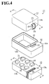
- Fig.4 is a perspective view of an electrical connector housing according to a first embodiment of the invention, when it is disassembled into constituent units;
- Fig.5 is a partially exploded top plan view of a lower shell of an embodiment of the invention;
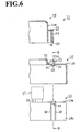
- Fig.6 is a cross-sectional view of the electrical connector housing of Fig.4, taken along line A-A of Fig.4;
- Fig.7 is a cross-sectional view of the electrical connector housing of Fig.4, when it is assembled and viewed along line A-A;
- Fig.8 is a cross-sectional view of the electrical connector housing of Fig.6, when viewed along line B-B; and
- Fig.9 is a top plan view of an electrical connector housing according to another embodiment of the invention.
-
- As shown in Fig.4, an
electrical connector housing 11 may comprise alower shell 12, a connector block (or electrical-parts fixing block) 13 and anupper shell 14. Thelower shell 12 has an opened bottom and anupper panel 12a, part of which forms anopening 15. The opening therefore has a surface smaller than that of theupper panel 12a. Thelower shell 12 fixedly contains aconnector block 13. The opening 15 is covered with anupper shell 14. - The
connector block 13 has a substantially parallelepiped shape, and formed so as to be contained in thelower shell 12. Theupper face 13a of theblock 13 carries a plurality (six in the present case) offixture ports 16 for electrical-parts, at given positions. Thefixture ports 16 are positioned such that, when theconnector block 13 is contained in thelower shell 12, they are exposed to the outside through theopening 15 of thelower shell 12. In other words, the portion ofupper face 12a of theblock 13 where fixture ports are not mounted is covered with theupper panel 12a of thelower shell 12. As shown by short and long dotted lines in Figs.6 and 7, thefixture ports 16 are engageable withelectrical apparatuses 17 such as relays and fusible links. The inside of theconnector block 13 is wired with bus bars or the like (not shown in the figures). A desired circuitry can thus be formed by this wiring. Such aconnector block 13 is fixed in thelower shell 12 by fixing mount means (not shown in the figures). - A first fixing mount means 21 is formed near the
opening 15 of theupper panel 12a of thelower shell 12, and holds theupper shell 14 in a freely engageable and removable way. As shown in Figs.6 and 7, the first fixing mount means 21 comprises a lockingclaw 21a which extends towards theopening 15. Theupper panel 12a includes adraw hole 22 at a position just under the lockingclaw 21a. As shown in Fig. 5, thisdraw hole 22 has a rectangular shape, viewed from the above. Thedraw hole 22 has a hole size slightly greater than the size of the lockingclaw 21 a. - The
outer side face 14a of theupper shell 14 comprises a second fixing mount means 23 at a position corresponding to that of the first fixing mount means 21 and is engageable therewith. The second fixing mount means 23 includes aflexible fin 24 which can be deformed in a direction shown by arrow F in Fig.6. The tip (facing downward) of theflexible fin 24 forms ahook portion 25 inclining towards the tip. Theupper shell 14 can thus be fixed on thelower shell 12 by hooking thehook portion 25 on the lockingclaw 21a. - As shown in Figs.5 to 8, the inner face of the
upper panel 12a is provided with arib 31. Therib 31 extends towards aside panel 12b of thelower shell 12, so as to form a rectangular cross-section and surround the three sides of the rectangular draw hole 22 (see Fig.5), and further extends from the inner face of theupper panel 12a downwards along the inner face of theside panel 12b. - The
upper face 13a of theconnector block 13 includespartition walls 32 at positions corresponding to the rectangular shape of therib 31. Thesepartition walls 32 are formed on the portion where thefixture ports 16 for the electrical parts are not located. As shown in Fig.7, when theconnector block 13 is mounted into thelower shell 12, thepartition walls 32 closely flank the outer faces of therib 31. To enable such a configuration, thepartition walls 32 are formed so as to extend from theupper face 13a of theconnector block 13 towards theirside face 13b, and further downwardly therefrom. - Accordingly, when the
connector block 13 is contained in thelower shell 12, it is separated from the space for thefixture ports 16 by therib 31 and thepartition walls 32. At the same time, there is formed a drainingspace 33 which connects to thedraw hole 22. Consequently, when water enters into thelower shell 12 of theelectrical connector housing 11 via thedraw hole 22, it can be drained away through the drainingspace 33. - Further, part of the
upper face 13a of theconnector block 13, geometrically corresponding to a position where the drainingspace 33 is installed, is inclined towards theside face 13b of theconnector block 13, so as to form aninclined portion 34. Water penetrating into theelectrical connector housing 11 thus runs down towards theside face 13b of theconnector block 13 along theinclined portion 34, and is drained out towards the underneath of thelower shell 12. Draining of the water is swift and efficient. - As a result, the present invention provides the following technical effects:
- The first and the second fixing mount means 21 and 23 are contained within the area framework of the upper face of the
lower shell 12, so that they do not extend beyond the lower and theupper shells electrical connector housing 11 can thus be kept small. - Further, water entering into the
electrical connector housing 11 via thedraw hole 22 runs down through the drainingspace 33 formed by therib 31 which is provided on thelower shell 12, and thepartition walls 32 which are provided on theconnector block 13. Moreover, the drainingspace 33 is separated from the space forfixture ports 16, so that water running down the drainingspace 33 cannot penetrate into the latter space. The electrical connector housing thus maintains a high waterproof quality. - Although the
lower shell 12 includes arib 31, it can be formed without using a complex die. Production costs of theelectrical connector housing 11 can thus be kept to minimum. - Water entering into the draining
space 33 via thedraw hole 22 runs down along theinclined portion 34 and is drained out beyond theside face 13b of theconnector block 13. This draining is swift and efficient. Accordingly, the space forfixture ports 16 is efficiently protected from water penetration. - In the
lower shell 12, therib 31 extends from top of the inner face of shell'sside panel 12b to the bottom thereof. In theconnector block 13, thepartition walls 32 extend from top of itsside face 13b to bottom thereof. Accordingly, in theconnector block 13, water enters the drainingspace 33 and runs down towards theside face 13b of theblock 13, and is then drained out underneath theblock 13 and thelower shell 12. The space for thefixture ports 16 is thus securely protected from water penetration. - The
rib 31 and thepartition walls 32 are closely superposed, so that, even if water enters the drainingspace 33, it is nonetheless prevented from entering the space provided for thefixture ports 16. - The
partition walls 32 are formed away from thefixture ports 16 for electrical-parts, so that the drainingspace 33 is also formed distantly from thefixture ports 16. The latter 16 is thus more securely protected from water penetration. - In another embodiment of the invention, the shape of the
electrical connector housing 11 can be modified as desired. As shown in Fig.9, it can take substantially an L configuration (a second electrical connector housing 41). The secondelectrical connector housing 41 may separately contain twoconnector blocks upper shells upper shells lower shell 46. As shown by short and long dotted lines in Fig.9, a second fixing mount means 23 and a corresponding first fixing mount means 21 of a firstupper shell 45 are positioned on thelower shell 46. As these fixing mount means 21 and 23 do not extend beyond the surface framework of theelectrical connector housing 41, the size thereof is not enlarged. Further, by dividing the upper shell into twoparts - Alternatively, the
rib 31 formed on the inner face of theside panel 12b oflower shell 12, as well as thepartition walls 32 formed on theside face 13b of theconnector block 13 may be dispensed with. The form of thelower shell 12 and theconnector block 13 can thus be simplified. - Alternatively yet, the
inclined portion 34 may be eliminated and made flat. Even then, the electrical-parts fixture sites 16 may be protected against water penetration. - Such
electrical connector housings 11 may be mounted not only in automobiles or wagons, but also in industrial machinery. - Besides what has been described above, the electrical connector housings according to the invention provide the following technical features and advantages.
- The partition walls described above are formed farther from the electrical-
parts fixture ports 16. Accordingly, even if water penetrates into theelectrical connector housing 11, the water is still prevented from reaching thefixture ports 16. - Typically, the electrical connector housing of the invention is mounted in automobiles or vehicles, more specifically in engine compartments of such moving means.
- By virtue of the above configuration, the size of the electrical connector housing can be kept as small as possible, whilst the production costs thereof can be maintained as low as possible. Moreover, the waterproof quality of the electrical connector housing is improved.
- Furthermore, water penetration into the space for the electrical-parts fixture ports is securely prevented.
Claims (4)
- An electrical connector housing (11) comprising a lower shell (12) including an upper panel (12a) with at least one opening (15) and a side panel (12b), at least one connector block (13) including fixture ports (16) provided thereon and being contained in said lower shell, and at least one upper shell (14) covering said opening(s) (15) of said upper panel (12a) in a freely engageable and removable way,said upper panel (12a) of said lower shell (12) including at least one first fixing mount means (21) with a locking claw (21a) and at least one draw hole (22) both positioned outside said opening(s) (15), said upper shell(s) (14) comprising an outer side face (14a) including at least one second fixing mount means (23), such that said draw hole(s) (22) can be used for forming said locking claw (21a) and such that said second fixing mount means (23) is/are freely engageable with, and removable from, said first fixing mount means (21), characterised in that;said upper panel (12a) of said lower shell (12) has an inner face comprising at least one rib (31) which is placed near said draw hole(s) (22) and extends towards said side panel (12b) of said lower shell (12) while surrounding said draw hole(s) (22), and said upper face (13a) of said connector block(s) (13) comprises a pair of partition walls (32) at a position corresponding to that of said rib(s) (31), so that, when said connector block(s) (13) is/are inserted into said lower shell (12), said rib(s) (31) is/are interposed between said partition walls (32), thereby forming a draining space (33) away from a space for said fixture ports (16).
- The electrical connector housing (41) according to claim 1, wherein said electrical connector housing (41) comprises a lower shell (46) which is formed substantially in an L-shape, viewed from the above, and includes an upper panel with two openings, said electrical connector housing (41) further comprises two separate connector blocks (42, 43) and two separate corresponding upper shells (44, 45), and at least one of said two openings, two connector blocks (42, 43) and two upper shells (44, 45) involve a corresponding draw hole and first and second fixing mount means (21, 23).
- The electrical connector housing (11, 41) according to claim 1 or 2, wherein said rib(s) (31) further extend(s) from top to bottom on an inner face of said side panel (12b) in said lower shell (12), and said pair of partition walls (32) further extends from top to bottom on said side face (13b) of said connector block (13).
- The electrical connector housing (11, 41) according to any one of claims 1 to 3, wherein said upper face (13a) of said connector block (13) has an enclosed portion between said partition walls (32) and said enclosed portion includes a portion (34) inclining towards said side face (13b) of said connector block (13).
Applications Claiming Priority (2)
| Application Number | Priority Date | Filing Date | Title |
|---|---|---|---|
| JP34364399A JP3463632B2 (en) | 1999-12-02 | 1999-12-02 | Electrical junction box |
| JP34364399 | 1999-12-02 |
Publications (1)
| Publication Number | Publication Date |
|---|---|
| EP1107278A2 true EP1107278A2 (en) | 2001-06-13 |
Family
ID=18363124
Family Applications (1)
| Application Number | Title | Priority Date | Filing Date |
|---|---|---|---|
| EP00403355A Withdrawn EP1107278A2 (en) | 1999-12-02 | 2000-11-30 | Electrical connector housing |
Country Status (3)
| Country | Link |
|---|---|
| US (1) | US6319057B2 (en) |
| EP (1) | EP1107278A2 (en) |
| JP (1) | JP3463632B2 (en) |
Cited By (4)
| Publication number | Priority date | Publication date | Assignee | Title |
|---|---|---|---|---|
| EP2056658A3 (en) * | 2007-10-26 | 2009-05-27 | Sumitomo Wiring Systems, Ltd. | Electrical junction box to be mounted on a motor vehicle |
| FR2951865A1 (en) * | 2009-10-22 | 2011-04-29 | Yazaki Corp | Circuit breaker for supply source in electric vehicle, has housing receiving fuse-element, cover provided with internal tubular part of tube, and tubular wall part of another housing extended perpendicularly from lower wall part |
| WO2013105671A1 (en) * | 2012-01-13 | 2013-07-18 | Yazaki Corporation | Junction box |
| CN109275302A (en) * | 2017-07-17 | 2019-01-25 | 青岛海尔洗衣机有限公司 | Waterproof cover for electronic components |
Families Citing this family (21)
| Publication number | Priority date | Publication date | Assignee | Title |
|---|---|---|---|---|
| JP2002112435A (en) * | 2000-09-27 | 2002-04-12 | Sumitomo Wiring Syst Ltd | Electrical junction box for high voltage |
| US7077667B2 (en) * | 2003-04-22 | 2006-07-18 | Yazaki Corporation | Electrical junction box |
| JP4265990B2 (en) * | 2004-04-12 | 2009-05-20 | 株式会社オートネットワーク技術研究所 | Electrical junction box |
| US7285000B2 (en) * | 2005-08-12 | 2007-10-23 | Harris Corporation | Electro-fluidic interconnect attachment |
| JP5099900B2 (en) | 2008-01-29 | 2012-12-19 | 矢崎総業株式会社 | Electrical junction box |
| JP5120135B2 (en) * | 2008-08-04 | 2013-01-16 | 住友電装株式会社 | Electrical junction box |
| JP5332988B2 (en) * | 2009-07-10 | 2013-11-06 | 住友電装株式会社 | Electrical junction box |
| EP2820928B1 (en) * | 2012-02-28 | 2017-07-19 | Telefonaktiebolaget LM Ericsson (publ) | Housing for electronic components |
| JP6035630B2 (en) * | 2012-05-22 | 2016-11-30 | 矢崎総業株式会社 | Electrical junction box |
| JP6522929B2 (en) * | 2014-11-27 | 2019-05-29 | 矢崎総業株式会社 | Protective cover |
| JP6443307B2 (en) * | 2015-11-13 | 2018-12-26 | オムロン株式会社 | Drainage structure and power control device |
| JP6457919B2 (en) * | 2015-11-20 | 2019-01-23 | モレックス エルエルシー | connector |
| KR200484888Y1 (en) * | 2016-02-12 | 2017-11-03 | 엘에스산전 주식회사 | Fuse Case and Case Cover of Vacuum Contactor |
| JP6573078B2 (en) * | 2016-07-06 | 2019-09-11 | 住友電装株式会社 | Drainage structure of electrical junction box |
| CN106114417B (en) * | 2016-08-31 | 2018-01-26 | 重庆五洲龙新能源汽车有限公司 | The low-voltage distribution box of pure electric coach |
| JP6811129B2 (en) * | 2017-03-17 | 2021-01-13 | 株式会社村上開明堂 | Actuator installation structure |
| JP6811126B2 (en) * | 2017-03-17 | 2021-01-13 | 株式会社村上開明堂 | Actuator |
| JP6709511B2 (en) * | 2017-04-07 | 2020-06-17 | 住友電装株式会社 | Opening sealing member and electric device |
| JP7348134B2 (en) * | 2020-05-18 | 2023-09-20 | 矢崎総業株式会社 | resin structure |
| CN111836499A (en) * | 2020-08-19 | 2020-10-27 | 孙晋明 | A new type of flameproof shell structure |
| JP7201650B2 (en) * | 2020-10-12 | 2023-01-10 | 矢崎総業株式会社 | Resin structure |
Family Cites Families (5)
| Publication number | Priority date | Publication date | Assignee | Title |
|---|---|---|---|---|
| JPH0731513Y2 (en) * | 1987-09-18 | 1995-07-19 | 矢崎総業株式会社 | Electrical junction box |
| JP2988237B2 (en) * | 1994-01-31 | 1999-12-13 | 住友電装株式会社 | Simple waterproof connector |
| JPH07309047A (en) | 1994-05-18 | 1995-11-28 | Shimadzu Corp | Serial printer |
| JP3527000B2 (en) * | 1996-01-26 | 2004-05-17 | 本田技研工業株式会社 | Switch box with connector |
| US6200169B1 (en) * | 1999-10-28 | 2001-03-13 | Tseng Jeou-Nan | Wire connector for a decorative lamp |
-
1999
- 1999-12-02 JP JP34364399A patent/JP3463632B2/en not_active Expired - Fee Related
-
2000
- 2000-11-30 EP EP00403355A patent/EP1107278A2/en not_active Withdrawn
- 2000-12-01 US US09/726,343 patent/US6319057B2/en not_active Expired - Fee Related
Non-Patent Citations (1)
| Title |
|---|
| None |
Cited By (9)
| Publication number | Priority date | Publication date | Assignee | Title |
|---|---|---|---|---|
| EP2056658A3 (en) * | 2007-10-26 | 2009-05-27 | Sumitomo Wiring Systems, Ltd. | Electrical junction box to be mounted on a motor vehicle |
| CN101420106B (en) * | 2007-10-26 | 2011-09-07 | 住友电装株式会社 | Electrical junction box to be mounted on a motor vehicle |
| FR2951865A1 (en) * | 2009-10-22 | 2011-04-29 | Yazaki Corp | Circuit breaker for supply source in electric vehicle, has housing receiving fuse-element, cover provided with internal tubular part of tube, and tubular wall part of another housing extended perpendicularly from lower wall part |
| WO2013105671A1 (en) * | 2012-01-13 | 2013-07-18 | Yazaki Corporation | Junction box |
| CN104039600A (en) * | 2012-01-13 | 2014-09-10 | 矢崎总业株式会社 | Junction box |
| US9331462B2 (en) | 2012-01-13 | 2016-05-03 | Yazaki Corporation | Junction box |
| CN104039600B (en) * | 2012-01-13 | 2016-05-11 | 矢崎总业株式会社 | Junction box |
| CN109275302A (en) * | 2017-07-17 | 2019-01-25 | 青岛海尔洗衣机有限公司 | Waterproof cover for electronic components |
| CN109275302B (en) * | 2017-07-17 | 2021-03-19 | 青岛海尔洗衣机有限公司 | Waterproof cover for electronic components |
Also Published As
| Publication number | Publication date |
|---|---|
| US20010003069A1 (en) | 2001-06-07 |
| JP2001169437A (en) | 2001-06-22 |
| JP3463632B2 (en) | 2003-11-05 |
| US6319057B2 (en) | 2001-11-20 |
Similar Documents
| Publication | Publication Date | Title |
|---|---|---|
| US6319057B2 (en) | Electrical connector housing | |
| US6545217B2 (en) | Electrical junction box having double-wall structure | |
| US20100307814A1 (en) | Electric connection box | |
| JP7116027B2 (en) | Electrical Junction Box and Wire Harness | |
| US20100326690A1 (en) | Electrical junction box | |
| US6971888B2 (en) | Waterproof structure of electric junction box | |
| JP2002058128A (en) | Electrical junction box | |
| JP2013146126A (en) | Electric connection box | |
| US9578774B2 (en) | Electronic component unit | |
| JP2010074955A (en) | Electric connection box | |
| US7357650B2 (en) | Electrical connection box | |
| US5967819A (en) | Electric junction box and method for mounting a bus bar in same | |
| JP5741945B2 (en) | Electrical junction box | |
| JP5719535B2 (en) | Waterproof case | |
| JP3501071B2 (en) | Electrical junction box | |
| JP5068054B2 (en) | Electrical junction box mounting structure | |
| JP3334621B2 (en) | Electrical junction box and outlet | |
| JP3923273B2 (en) | Electrical junction box | |
| JP3311657B2 (en) | Electrical junction box | |
| JPH08322124A (en) | Waterproof structure of electrical junction box | |
| JPH0684730U (en) | Branch connection box | |
| JP2003009349A (en) | Waterproof structure of electrical junction box | |
| JP3933998B2 (en) | Electrical junction box | |
| US10462914B2 (en) | Cover structure and electric connection box | |
| JP2006060877A (en) | Electrical connection box |
Legal Events
| Date | Code | Title | Description |
|---|---|---|---|
| PUAI | Public reference made under article 153(3) epc to a published international application that has entered the european phase |
Free format text: ORIGINAL CODE: 0009012 |
|
| 17P | Request for examination filed |
Effective date: 20001208 |
|
| AK | Designated contracting states |
Kind code of ref document: A2 Designated state(s): AT BE CH CY DE DK ES FI FR GB GR IE IT LI LU MC NL PT SE TR |
|
| AX | Request for extension of the european patent |
Free format text: AL;LT;LV;MK;RO;SI |
|
| STAA | Information on the status of an ep patent application or granted ep patent |
Free format text: STATUS: THE APPLICATION HAS BEEN WITHDRAWN |
|
| 18W | Application withdrawn |
Withdrawal date: 20011121 |