EP1107275A2 - Fuse unit and manufacturing method therefor - Google Patents
Fuse unit and manufacturing method therefor Download PDFInfo
- Publication number
- EP1107275A2 EP1107275A2 EP00403356A EP00403356A EP1107275A2 EP 1107275 A2 EP1107275 A2 EP 1107275A2 EP 00403356 A EP00403356 A EP 00403356A EP 00403356 A EP00403356 A EP 00403356A EP 1107275 A2 EP1107275 A2 EP 1107275A2
- Authority
- EP
- European Patent Office
- Prior art keywords
- fuse
- input terminal
- fuse element
- output terminal
- fuse unit
- Prior art date
- Legal status (The legal status is an assumption and is not a legal conclusion. Google has not performed a legal analysis and makes no representation as to the accuracy of the status listed.)
- Granted
Links
- 238000004519 manufacturing process Methods 0.000 title description 10
- 239000012212 insulator Substances 0.000 claims abstract description 33
- 239000000463 material Substances 0.000 claims abstract description 31
- 238000000034 method Methods 0.000 claims description 13
- 238000000465 moulding Methods 0.000 claims description 13
- 238000005192 partition Methods 0.000 claims description 6
- 229910052751 metal Inorganic materials 0.000 abstract description 9
- 239000002184 metal Substances 0.000 abstract description 9
- 229920005989 resin Polymers 0.000 description 23
- 239000011347 resin Substances 0.000 description 23
- 238000005452 bending Methods 0.000 description 5
- 230000002093 peripheral effect Effects 0.000 description 5
- 238000010276 construction Methods 0.000 description 4
- 238000005530 etching Methods 0.000 description 2
- RYGMFSIKBFXOCR-UHFFFAOYSA-N Copper Chemical compound [Cu] RYGMFSIKBFXOCR-UHFFFAOYSA-N 0.000 description 1
- BQCADISMDOOEFD-UHFFFAOYSA-N Silver Chemical compound [Ag] BQCADISMDOOEFD-UHFFFAOYSA-N 0.000 description 1
- ATJFFYVFTNAWJD-UHFFFAOYSA-N Tin Chemical compound [Sn] ATJFFYVFTNAWJD-UHFFFAOYSA-N 0.000 description 1
- HCHKCACWOHOZIP-UHFFFAOYSA-N Zinc Chemical compound [Zn] HCHKCACWOHOZIP-UHFFFAOYSA-N 0.000 description 1
- 239000000956 alloy Substances 0.000 description 1
- 229910045601 alloy Inorganic materials 0.000 description 1
- 230000000712 assembly Effects 0.000 description 1
- 238000000429 assembly Methods 0.000 description 1
- 230000015572 biosynthetic process Effects 0.000 description 1
- 229910052802 copper Inorganic materials 0.000 description 1
- 239000010949 copper Substances 0.000 description 1
- 230000000694 effects Effects 0.000 description 1
- 239000013013 elastic material Substances 0.000 description 1
- 239000003822 epoxy resin Substances 0.000 description 1
- 230000001939 inductive effect Effects 0.000 description 1
- 238000003780 insertion Methods 0.000 description 1
- 230000037431 insertion Effects 0.000 description 1
- 239000011133 lead Substances 0.000 description 1
- 150000002739 metals Chemical class 0.000 description 1
- 229920000647 polyepoxide Polymers 0.000 description 1
- 238000002360 preparation method Methods 0.000 description 1
- 229910052709 silver Inorganic materials 0.000 description 1
- 239000004332 silver Substances 0.000 description 1
- 238000005728 strengthening Methods 0.000 description 1
- 229910052718 tin Inorganic materials 0.000 description 1
- 239000011135 tin Substances 0.000 description 1
- 229910052725 zinc Inorganic materials 0.000 description 1
- 239000011701 zinc Substances 0.000 description 1
Images




Classifications
-
- H—ELECTRICITY
- H01—ELECTRIC ELEMENTS
- H01H—ELECTRIC SWITCHES; RELAYS; SELECTORS; EMERGENCY PROTECTIVE DEVICES
- H01H85/00—Protective devices in which the current flows through a part of fusible material and this current is interrupted by displacement of the fusible material when this current becomes excessive
- H01H85/02—Details
- H01H85/04—Fuses, i.e. expendable parts of the protective device, e.g. cartridges
- H01H85/041—Fuses, i.e. expendable parts of the protective device, e.g. cartridges characterised by the type
- H01H85/044—General constructions or structure of low voltage fuses, i.e. below 1000 V, or of fuses where the applicable voltage is not specified
-
- H—ELECTRICITY
- H01—ELECTRIC ELEMENTS
- H01H—ELECTRIC SWITCHES; RELAYS; SELECTORS; EMERGENCY PROTECTIVE DEVICES
- H01H85/00—Protective devices in which the current flows through a part of fusible material and this current is interrupted by displacement of the fusible material when this current becomes excessive
- H01H85/0013—Means for preventing damage, e.g. by ambient influences to the fuse
- H01H85/0021—Means for preventing damage, e.g. by ambient influences to the fuse water or dustproof devices
- H01H2085/0034—Means for preventing damage, e.g. by ambient influences to the fuse water or dustproof devices with molded casings
-
- H—ELECTRICITY
- H01—ELECTRIC ELEMENTS
- H01H—ELECTRIC SWITCHES; RELAYS; SELECTORS; EMERGENCY PROTECTIVE DEVICES
- H01H85/00—Protective devices in which the current flows through a part of fusible material and this current is interrupted by displacement of the fusible material when this current becomes excessive
- H01H85/02—Details
- H01H85/0241—Structural association of a fuse and another component or apparatus
- H01H2085/025—Structural association with a binding post of a storage battery
-
- H—ELECTRICITY
- H01—ELECTRIC ELEMENTS
- H01H—ELECTRIC SWITCHES; RELAYS; SELECTORS; EMERGENCY PROTECTIVE DEVICES
- H01H85/00—Protective devices in which the current flows through a part of fusible material and this current is interrupted by displacement of the fusible material when this current becomes excessive
- H01H85/02—Details
- H01H85/04—Fuses, i.e. expendable parts of the protective device, e.g. cartridges
- H01H85/05—Component parts thereof
- H01H85/055—Fusible members
- H01H2085/0555—Input terminal connected to a plurality of output terminals, e.g. multielectrode
-
- H—ELECTRICITY
- H01—ELECTRIC ELEMENTS
- H01H—ELECTRIC SWITCHES; RELAYS; SELECTORS; EMERGENCY PROTECTIVE DEVICES
- H01H69/00—Apparatus or processes for the manufacture of emergency protective devices
- H01H69/02—Manufacture of fuses
-
- H—ELECTRICITY
- H01—ELECTRIC ELEMENTS
- H01H—ELECTRIC SWITCHES; RELAYS; SELECTORS; EMERGENCY PROTECTIVE DEVICES
- H01H85/00—Protective devices in which the current flows through a part of fusible material and this current is interrupted by displacement of the fusible material when this current becomes excessive
- H01H85/02—Details
- H01H85/20—Bases for supporting the fuse; Separate parts thereof
- H01H85/2045—Mounting means or insulating parts of the base, e.g. covers, casings
-
- Y—GENERAL TAGGING OF NEW TECHNOLOGICAL DEVELOPMENTS; GENERAL TAGGING OF CROSS-SECTIONAL TECHNOLOGIES SPANNING OVER SEVERAL SECTIONS OF THE IPC; TECHNICAL SUBJECTS COVERED BY FORMER USPC CROSS-REFERENCE ART COLLECTIONS [XRACs] AND DIGESTS
- Y10—TECHNICAL SUBJECTS COVERED BY FORMER USPC
- Y10T—TECHNICAL SUBJECTS COVERED BY FORMER US CLASSIFICATION
- Y10T29/00—Metal working
- Y10T29/49—Method of mechanical manufacture
- Y10T29/49002—Electrical device making
- Y10T29/49107—Fuse making
-
- Y—GENERAL TAGGING OF NEW TECHNOLOGICAL DEVELOPMENTS; GENERAL TAGGING OF CROSS-SECTIONAL TECHNOLOGIES SPANNING OVER SEVERAL SECTIONS OF THE IPC; TECHNICAL SUBJECTS COVERED BY FORMER USPC CROSS-REFERENCE ART COLLECTIONS [XRACs] AND DIGESTS
- Y10—TECHNICAL SUBJECTS COVERED BY FORMER USPC
- Y10T—TECHNICAL SUBJECTS COVERED BY FORMER US CLASSIFICATION
- Y10T29/00—Metal working
- Y10T29/49—Method of mechanical manufacture
- Y10T29/49002—Electrical device making
- Y10T29/49117—Conductor or circuit manufacturing
Definitions
- the present invention generally pertains to fuse units and their manufacturing method. It further relates to a fuse box, with a fuse cover, adapted to contain the fuse unit. Such a fuse box can be suitably used in vehicles, e.g. automobiles.
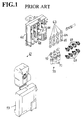
- FIG.1 shows an example of a known fuse box unit which is directly connectable to a battery.
- a fuse box unit 61 comprises a fuse box 62, flat fuses 63 and other components.
- the flat fuses 63 are formed by stamping out an electrically conductive metal plate or sheet.
- Each flat fuse 63 includes a fuse element portion 64 formed in a curved plane and interposed between two ear portions 65 having a respective ear hole for bolting.
- the fuse element portion 64 is fusible, and its width is set as a function of the current required to be passed.
- the fuse box 62 is made of a resin, and includes a plurality of enclosures 66 which can contain the corresponding number of flat fuses 63.
- a pair of flat nuts (first flat nut 67 and second flat nut 68) is insert-molded on the base of each enclosure 66.
- the first flat nut 67 which is used for power input, has a first flat nut hole for bolting. From this first flat nut 67 extends a terminal directly connectable to a battery (not shown in the figures). Accordingly, a flat fuse 63 is installed and a bolt 69 can be screwed into the ear hole and the first flat nut hole, so that a first end of the flat fuse 63 is connected and fixed to the first flat nut 67 at the power input side.
- the second flat nut 68 has a second flat nut hole for bolting at a power output side. Accordingly, the flat fuse 63 is fixed by screwing down a bolt 69 into the second flat nut hole, so that the other end of the flat fuse 63 is connected to the second flat nut 68 at the power output side.
- Electrical cables 71 constituting a wire harness 70 are cramped respectively with an LA terminal 72. These LA terminals 72 are connected and fixed to the second flat nuts 68, together with the flat fuses 63, through the bolts 69. The fuse box 62 is then protected by placing a fuse cover 73 thereon.
- assembling various components into a fuse box unit 61 requires cumbersome work steps, such as a step of fixing a plurality of flat fuses 63 into a fuse box 62 by means of bolts 69 and first and second flat nuts 67 and 68.
- the prior art fuse box unit has a quite low operation efficiency when mounted.
- a prior art fuse box unit 61 must sometimes be constructed by using flat fuses 63 having different current ratings.
- fuse element portions 64 having different widths must be prepared as a function of their current capacity.
- several kinds of dies have to be used for stamping, incurring additional production costs.
- a first object of the invention is to provide a method of manufacturing a fuse unit in an easy and economical way, irrespective of the current capacity rating required and the number of fuse element portions.
- a second object of the invention is to provide a fuse unit which can be manufactured easily at a low cost according to the above method, which fuse unit is endowed with a sufficient mechanical strength and can be fixed easily into a fuse recipient, e.g. a fuse box.
- a fuse unit comprising an electrically conductive plate including an input terminal, at least one output terminal and at least one fuse element portion linking the input terminal and the output terminal(s), the fuse unit further comprising a insulator material, the method comprising the steps of:
- the molding step comprises molding a part of the area, such that at least one non-shielded portion is formed for the locus/loci
- the molding step comprises insert-molding a part of the area by means of a die including at least one protrusion, so that the protrusion(s) form(s) the non-shielded portion(s).
- the stamping step comprises stamping the electrically conductive plate so as to form the input terminal, the output terminal(s) having a respective end portion, and at least one tie bar linking the end portion(s) of the output terminal(s);
- the forming step may comprise stamping the locus/loci so as to yield the fuse element portion(s), whilst simultaneously removing the tie bar (s) by the stamping.
- the invention further relates to a fuse unit comprising an electrically conductive plate including an input terminal, at least one output terminal and at least one fuse element portion linking the input terminal and the output terminal(s), the fuse unit further comprising an area molded with an insulator material, the area including at least one opening, through which the fuse element portion(s) is/are exposed to outside the insulator material.
- the invention concerns also a fuse box containing a fuse unit, the fuse unit comprising an electrically conductive plate including an input terminal, at least one output terminal and at least one fuse element portion linking the input terminal and the output terminal(s), the fuse unit further comprising an area molded with an insulator material, the area including at least one opening, through which the fuse element portion(s) is/are exposed to outside the insulator material; the fuse box forming a hollow cylindrical shape having a substantially rectangular cross-section, and a top opening and a bottom opening, the fuse box containing at least one partition wall extending in the longitudinal direction of the cylindrical shape, thereby forming several enclosures lodging the output terminal(s), the partition wall(s) including a slit extending from the top opening to half-way downwards in the longitudinal direction, the slit(s) lodging the insulator material such that the input terminal extends perpendicularly to the longitudinal direction from the top opening.
- the fuse box may further comprise a fuse cover including a cover plate and a cover joint, the cover plate covering the input terminal of the fuse unit and the cover joint covering the top opening of the fuse box.
- the peripheral area around it is already reinforced by the insulator material. Accordingly, even when a thin fuse element portion must be formed, the stress, which may cause curving or bending of the fuse element, is hardly exerted towards the fuse element portion.
- the fuse element portion can thus be rendered less liable to deformation or breaking, and is secured with sufficient strength. Further, even when the fuse element portion must be given a small electrical current rating, it can be formed relatively easily. Further yet, several fuse element portions having a different thickness can be formed using only one kind of die. Costs incurred for die preparation can thus be reduced to minimum, and the fuse units can thus be produced at low cost.
- the end portions of the output terminals are linked to each other by tie bars.
- tie bars are removed by stamping at the same time as the fuse element portion is formed.
- the number of operation steps, as a whole, can thus be kept to a minimum, leading to improved production efficiency.
- the insulator material does not impede the stamping work. The latter is thus facilitated greatly. In such a case, even when the insulator material used is not sufficiently elastic, the generation of cracks is nonetheless prevented.
- the former can be inspected visually, irrespective of the insulator material used. Moreover, such a fuse unit can be constructed easily and economically when the above-mentioned method is applied.
- Figs.2 to 8 show a fuse unit 1 used in automobiles, according to an embodiment of the present invention.
- the fuse unit 1 is formed by incorporating an electrically conductive plate 2, e.g. a metal plate.
- the latter 2 includes e.g. a material made of silver, copper, zinc, tin, lead, or an alloy made with at least one of these metals.
- the conductive metal plate 2 is then formed into an input terminal 3, one or several output terminals 4 (also known as "male tabs 4") and one or several fuse element portions 5.
- the input terminal 3 can be directly connected to a power-supply terminal for a battery mounted in an automobile (not shown in the figures). This input terminal can therefore be qualified as a terminal directly connectable to a battery.
- An input terminal 3 comprises a first strip portion 3a (usually placed upright during use), and a second strip portion 3b (usually placed horizontally during use) which is narrower than the first strip portion 3a and arranged perpendicular thereto.
- a first end (left-hand side in Fig.2 (c)) of the second strip portion 3b is linked to a first end (top side in Fig.2 (c)) of the first strip portion 3a.
- the second strip portion 3b is configured so as to form a cross-section having an inverted U-shape (see top portion of Fig.2 (d)).
- a through hole 6 for bolt insertion is provided in the second strip portion 3b.
- the input terminal 3 is fixed to the power-supply terminal by fitting a bolt into the through hole 6 and a nut.
- the fuse unit 1 includes several units of male tabs 4 and corresponding fuse element portions 5.
- An example of the invention shown in Fig.2 contains four such units.
- Each fuse element portion 5 contained in the corresponding fuse unit 1 is made substantially narrower than the male tab 4, and wound into substantially a S-shaped configuration.
- a first end of each fuse element portion 5 leads to the first end of the second strip portion 3b.
- a second end of the fuse element portion 5 leads to a first end (upper end in Fig.2 (b)) of the male tab 4, which extends in a vertical direction in the same figure.
- the input terminal 3 is thus connected to each male tab 4 through each fuse element portion 5.
- An peripheral area of the fuse element portion 5 including the latter (which is formed in a conductive metal plate 2) is molded with an insulator resin. Such a peripheral area may cover the first strip portion 3a as a whole, and a top end portion of the male tab 4.
- the molded resin portion 7 thus produced may form a thin plate.
- such an insulator resin includes an epoxy resin.
- the molded resin portion 7 preferably includes four window portions 8 at predetermined positions.
- the window portions 8 may have a substantially square shape, as shown in Fig.2. Through these window portion 8 is exposed each fuse element portion 5 to the outside, beyond the molded resin portion 7.
- the fuse unit 1 of the present embodiment shown in Fig.2 is therefore in the form of a rake or fork.
- one input terminal 3 branches into four male tabs 4.
- the fuse unit 1 is manufactured according to the steps shown in Fig.3 (a), (b) and (c). First, there is provided an initial electrically conductive plate 2. The conductive plate 2 is then stamped out to yield, integrally, an input terminal 3, four male tabs 4 and corresponding tie bars 11.
- the tie bars 11 may have the same thickness as the conductive metal plate 2, but they may also be made thinner by, for example, half-etching. Preferably, each tie bar 11 is formed at a position uncovered by the molded resin portion 7, i.e. at a lower end portion of the male tab 4. Further, a through hole 6 for bolting (see Fig.2 (a)) may be formed at the same time as the metal plate 2 is stamped out.
- the transformed conductive plate 2 is then bent into a piece having a side cross-section of substantially L-shaped configuration, using a specific bending tool.
- An area including loci intended for subsequently lodging fuse element portions 5 (fuse-forming loci 12) is insert-molded in a suitable way with an insulator resin, so as to form a molded resin portion 7.
- the insert-molding is effected such as to form window portions 8.
- the insert-molding die may be provided e.g. with a convexity corresponding to the window portions 8.
- the exposed fuse-forming loci 12 are then formed into four fuse element portions 5 by stamping, whilst three tie bars 11 are removed by the same stamping operation.
- the male tabs 4 are thus separated from each other to form a desired fuse unit 1 shown in Fig.2.
- the fuse unit 1 thus produced is inserted into a fuse box 21 shown in Fig.4, prior to use.
- the fuse box 21 has a rectangular tubular shape, with top and bottom ends open.
- a top opening 22 and a bottom opening 24 thus have a rectangular surface, respectively.
- the outside rim portion of the top opening 22 is provided with a plurality of stopper means 27 and a flat fixture portion 28.
- the inside space of the fuse box 21 is separated into four enclosures by three insulator partition walls 23.
- the top and bottom openings 22 and 24 of the fuse box 21 are therefore defined by four square areas.
- the four enclosures form four spaces for containing terminals (not shown in the figures) to be press-fitted to an electrical cable.
- a portion of the inner face of fuse box 21, which inner face defines each of the four enclosures, is provided with a lance structure in order to hang the terminal therein.
- the other end of the terminal is press-fitted with a corresponding electrical cable which will constitute a wire harness.
- each partition wall 23 is provided with a slit 25 which extends vertically from the top to a point half-way downwards.
- the slits 25 have the same width for all the enclosures.
- the width of the slit 25 correspond to the thickness of the molded resin portion 7 of the fuse unit 1, so that the fuse unit 1 is fixed in the fuse box 21 by inserting the molded resin portion 7 into the slit 25 (see Fig.8).
- Two opposing positions on the smaller inner surfaces of the fuse box 21, which correspond to the cross points with a plane passing through the slits 25, are provided with a pair of guiding ribs 26, respectively.
- the two guiding ribs 26 of the same pair extend in parallel to each other, from top of the fuse box 21 to a point half-way downwards.
- the distance between the two guiding ribs 26 is arranged to correspond substantially to the thickness of the molded resin portion 7 of the fuse unit 1. Accordingly, when the fuse unit 1 is put into the fuse box 21, the two end rims of the molded resin portion 7 are held by the two pairs of guiding ribs 26 (see Fig.8 (a)).
- Figs.6 and 7 show a fuse cover 41 for protecting the fuse unit 1.
- the fuse cover 41 is made of an insulator material, e.g. a resin.
- the fuse cover 41 comprises a cover plate 42, a cover joint 43 and a hinge portion 44 combining them.
- the cover plate 42 covers and protects the power-supply terminal for a battery mounted e.g. in an automobile.
- the outer side face of the top of the cover plate 42 is marked with an indication to caution that it encloses a power-supply terminal.
- the cover joint 43 is mounted so as to close the top opening 22 of the fuse box 21.
- the cover joint 43 carries integrally formed hooking means 45 at positions corresponding to those of the stopper means 27.
- cover guiding ribs 46 there are provided two pairs of cover guiding ribs 46 on the rear face the cover joint 43.
- the distance between the cover guiding ribs 46 is designed to be substantially the same as the thickness of the molded resin portion 7 of the fuse unit 1. Accordingly, when the fuse unit 1 is installed and the fuse cover 41 is mounted, two end rims of the molded resin portion 7 are held by the two pairs of cover guiding ribs 46.
- the peripheral area of the element-forming loci 12 (intended to form the fuse element portions 5) is already reinforced with a molded resin portion 7.
- the fuse element portions 5 are less susceptible to stress which may otherwise cause curving or bending of the fuse elements.
- the fuse element portions 5 are more resistant to deformation or breaking, and maintain an appropriate strength during their manufacture.
- the fuse unit 1 however small their electric capacity is, can be manufactured relatively easily.
- fuse element portions 5 having different widths can be formed easily through one stamping die only. Costs incurred for preparing dies can thus be reduced to a minimum. As a consequence, the fuse units 1 and the entire assemblies containing these fuse units 1 can be produced at low costs.
- the end portions of adjacent male tabs 4 are initially linked to each other by tie bars 11.
- the structurally strengthening effect of this construction ensures that the mutual positions of the male tabs 4 are properly maintained, up to a moment when the fuse element portions 5 are formed by stamping.
- the fuse element portions 5 are protected from stress which may cause a curving or bending of the fuse elements. The fuse element portions 5 are thus less prone to deformation and breaking.
- the tie bars 11 can be removed at the same time as the fuse element portions 5 are formed. The presence of the tie bars 11 does therefore not increase the operation steps as a whole, while enabling the fuses units 1 to be manufactured easily and efficiently.
- the molded resin portion 7 does not impede such operation.
- the fuse element portions 5 can thus be formed very easily.
- the peripheral area of the fuse element portions 5, which tends to be mechanically weak, is protected by a molded resin portion 7, so that the fuse unit 1 procures by itself a sufficient mechanical strength.
- a molded resin portion 7 makes the fuse unit 1 more waterproof.
- the fuse element portion 5 is constantly exposed to the outside through the window portion 8.
- the fuse element portion 5 can thus be inspected visually, irrespective of the material used for the molded resin portion 7. For example, when the fuse element portion 5 is fused by the passage of an excessive current, this condition is easily detected by human eye.
- the structure of the fuse unit 1 may be modified very easily, so as to produce variant embodiments as follows.
- male tabs 4 used as output terminals is not limited to four, exemplified in the above embodiment. It may be one, two or three. It may also be more than four. The form of male tabs 4 may also be modified as desired.
- the input terminal 3 may have a configuration other than the one described above, or may not include the through hole 6 for bolting.
- the number of fuse element portions 5 may also be reduced to one.
- the insulator material used is not limited to the above-mentioned molded resin portion 7, but may be e.g. rubber. Likewise, the insulator material may be formed according to a method other than the insert-molding.
- a fuse element portion 5 can be formed by stamping, without forming the window portion 8.
- One reason for allowing such a formation step is that, as the rubber is a good elastic material, there forms little stress inside the rubber, and consequently no crack will be formed through such operation.
- tie bars 11 may be removed at the same time as the fuse element portion 5 is formed by stamping. But they may also be eliminated in a separate process. Moreover, when the fuse element portion 5 risks no deformation or breaking-up, the use of tie bars 11 may not be required.
- the fuse element portion 5 may also be formed by e.g. etching.
- the window portion 8 may be in a form other than a rectangular form, e.g. a circular or triangular form.
- the window portion 8 may also be one single large unit including a plurality of fuse-forming loci 12, thereby forming one common window portion 8.
- the input terminal of the present invention can be connected directly to a power-supply terminal of batteries.
- the input terminal of the invention can be used for the power-supply terminal for batteries in an automobile.
- each of the output terminals may be in the form of a male tab, which can be connected to a press-fixing terminal provided in a wire harness.
- the fuse unit can be connected to a wire harness in a very secured way.
- the fuse unit may be substantially in the shape of a rake or fork.
- the input terminal may be provided with a bolt hole, which may not be covered with the insulator material. By fixing with bolts, the input terminal can be fixed to the power-supply means in a more secured manner.
- the tie bars may be rendered thinner than the electrically conductive plate.
- the tie bars are thus very easily stamped away.
- the tie bars may be formed outside the area where the insulator material is coated.
- the tie bars can thus be eliminated, without removing the insulator material.
- the input terminal and the output terminals are first formed with the electrically conductive plate.
- An area of the conductive plate including the loci, where the fuse element portions should be formed later, is then molded with an insulator material. These loci for fuse element are subsequently transformed into fuse element portions. Accordingly, irrespective of their thickness, the fuse element portions can be formed at a predetermined position, in an easy and economical way.
- an area portion of the electrically conductive plate (which may include an input terminal, several output terminals and several fuse element portions linking them) is molded with an insulator material.
- the insulator material is provided with window portions, through which the fuse element portions are exposed to the outside.
- This fuse unit can be constructed easily and at a low cost. Further, the fuse unit obtained procures a sufficient mechanical strength, and can be easily mounted into a fuse box. Furthermore, the fuse element portions can be inspected by direct observation.
- a main advantage of the invention is that the fuse unit is manufactured in a easy and economical way, irrespective of the current capacity and number of the fuse element portions.
- a further advantage consists in the fact that the fuse element portions are protected from deformation or breaking while manufacturing the fuse unit.
- the fuse element portions can be inspected through a direct eye observation.
Landscapes
- Fuses (AREA)
Abstract
Description
- The present invention generally pertains to fuse units and their manufacturing method. It further relates to a fuse box, with a fuse cover, adapted to contain the fuse unit. Such a fuse box can be suitably used in vehicles, e.g. automobiles.
- Fig.1 shows an example of a known fuse box unit which is directly connectable to a battery. A fuse box unit 61 comprises a
fuse box 62,flat fuses 63 and other components. Theflat fuses 63 are formed by stamping out an electrically conductive metal plate or sheet. Eachflat fuse 63 includes afuse element portion 64 formed in a curved plane and interposed between two ear portions 65 having a respective ear hole for bolting. Thefuse element portion 64 is fusible, and its width is set as a function of the current required to be passed. Thefuse box 62 is made of a resin, and includes a plurality ofenclosures 66 which can contain the corresponding number offlat fuses 63. A pair of flat nuts (firstflat nut 67 and second flat nut 68) is insert-molded on the base of eachenclosure 66. The firstflat nut 67, which is used for power input, has a first flat nut hole for bolting. From this firstflat nut 67 extends a terminal directly connectable to a battery (not shown in the figures). Accordingly, aflat fuse 63 is installed and abolt 69 can be screwed into the ear hole and the first flat nut hole, so that a first end of theflat fuse 63 is connected and fixed to the firstflat nut 67 at the power input side. Likewise, the secondflat nut 68 has a second flat nut hole for bolting at a power output side. Accordingly, theflat fuse 63 is fixed by screwing down abolt 69 into the second flat nut hole, so that the other end of theflat fuse 63 is connected to the secondflat nut 68 at the power output side. -
Electrical cables 71 constituting awire harness 70 are cramped respectively with anLA terminal 72. TheseLA terminals 72 are connected and fixed to the secondflat nuts 68, together with theflat fuses 63, through thebolts 69. Thefuse box 62 is then protected by placing afuse cover 73 thereon. - However, when a
fuse element portion 64 is to be made narrower than a usual size, it tends to curve or bend, and theflat fuse 63 produced therefrom cannot be endowed with sufficient mechanical strength. Moreover, it is difficult to manufacture aflat fuse 63 having a small electrical current capacity. - Further, assembling various components into a fuse box unit 61 requires cumbersome work steps, such as a step of fixing a plurality of
flat fuses 63 into afuse box 62 by means ofbolts 69 and first and secondflat nuts - Furthermore, a prior art fuse box unit 61 must sometimes be constructed by using
flat fuses 63 having different current ratings. In such a case,fuse element portions 64 having different widths must be prepared as a function of their current capacity. As a result, several kinds of dies have to be used for stamping, incurring additional production costs. - The present invention was contemplated in the light of the above problems. A first object of the invention is to provide a method of manufacturing a fuse unit in an easy and economical way, irrespective of the current capacity rating required and the number of fuse element portions.
- A second object of the invention is to provide a fuse unit which can be manufactured easily at a low cost according to the above method, which fuse unit is endowed with a sufficient mechanical strength and can be fixed easily into a fuse recipient, e.g. a fuse box.
- To this end, there is provided a method of forming a fuse unit comprising an electrically conductive plate including an input terminal, at least one output terminal and at least one fuse element portion linking the input terminal and the output terminal(s), the fuse unit further comprising a insulator material, the method comprising the steps of:
- stamping the electrically conductive plate so as to form the input terminal and the output terminal(s);
- providing at least one locus predetermined for forming the fuse element portion(s);
- molding all or part of an area including the locus/loci with the insulator material; and
- forming the fuse element portion(s) at the locus/loci.
-
- Preferably, the molding step comprises molding a part of the area, such that at least one non-shielded portion is formed for the locus/loci
- Suitably, the molding step comprises insert-molding a part of the area by means of a die including at least one protrusion, so that the protrusion(s) form(s) the non-shielded portion(s).
- Preferably yet, the stamping step comprises stamping the electrically conductive plate so as to form the input terminal, the output terminal(s) having a respective end portion, and at least one tie bar linking the end portion(s) of the output terminal(s);
- Further yet, the forming step may comprise stamping the locus/loci so as to yield the fuse element portion(s), whilst simultaneously removing the tie bar (s) by the stamping.
- The invention further relates to a fuse unit comprising an electrically conductive plate including an input terminal, at least one output terminal and at least one fuse element portion linking the input terminal and the output terminal(s), the fuse unit further comprising an area molded with an insulator material, the area including at least one opening, through which the fuse element portion(s) is/are exposed to outside the insulator material.
- The invention concerns also a fuse box containing a fuse unit, the fuse unit comprising an electrically conductive plate including an input terminal, at least one output terminal and at least one fuse element portion linking the input terminal and the output terminal(s), the fuse unit further comprising an area molded with an insulator material, the area including at least one opening, through which the fuse element portion(s) is/are exposed to outside the insulator material;
the fuse box forming a hollow cylindrical shape having a substantially rectangular cross-section, and a top opening and a bottom opening, the fuse box containing at least one partition wall extending in the longitudinal direction of the cylindrical shape, thereby forming several enclosures lodging the output terminal(s), the partition wall(s) including a slit extending from the top opening to half-way downwards in the longitudinal direction, the slit(s) lodging the insulator material such that the input terminal extends perpendicularly to the longitudinal direction from the top opening. - The fuse box may further comprise a fuse cover including a cover plate and a cover joint, the cover plate covering the input terminal of the fuse unit and the cover joint covering the top opening of the fuse box.
- In the first aspect of the invention, when the fuse element portion is being built, the peripheral area around it is already reinforced by the insulator material. Accordingly, even when a thin fuse element portion must be formed, the stress, which may cause curving or bending of the fuse element, is hardly exerted towards the fuse element portion. The fuse element portion can thus be rendered less liable to deformation or breaking, and is secured with sufficient strength. Further, even when the fuse element portion must be given a small electrical current rating, it can be formed relatively easily. Further yet, several fuse element portions having a different thickness can be formed using only one kind of die. Costs incurred for die preparation can thus be reduced to minimum, and the fuse units can thus be produced at low cost.
- In a second aspect of the invention, the end portions of the output terminals are linked to each other by tie bars. By virtue of this configuration, the relative positions of the output terminals are kept constant, up to a moment when the fuse element portions are formed by stamping. Further, it is more difficult to exert curving- or bending-inducing stress on the fuse element portion. As a result, the fuse element portion is securely prevented from deformation or breaking.
- Further, the tie bars are removed by stamping at the same time as the fuse element portion is formed. The number of operation steps, as a whole, can thus be kept to a minimum, leading to improved production efficiency.
- When the loci exposing through the window portions are stamped out, the insulator material does not impede the stamping work. The latter is thus facilitated greatly. In such a case, even when the insulator material used is not sufficiently elastic, the generation of cracks is nonetheless prevented.
- In a third aspect of the invention, as the fuse element portion is exposed through the window portion, the former can be inspected visually, irrespective of the insulator material used. Moreover, such a fuse unit can be constructed easily and economically when the above-mentioned method is applied.
- The above and the other objects, features and advantages of the present invention will be made apparent from the following description of the preferred embodiments, given as non-limiting examples, with reference to the accompanying drawings, in which:
- Fig.1 is a perspective view of a disassembled fuse box known in the prior art;
- Figs.2 (a), (b), (c) and (d) are, respectively, a top plan view, a front elevational view, a side elevational view and a rear elevational view of a fuse unit according to the present invention;
- Figs.3 (a), (b) and (c) are, respectively, front elevational views of the inventive fuse unit, explaining how the fuse unit is manufactured;
- Figs.4 (a), (b), (c) and (d) are, respectively, a top plan view, a front elevational view, a side elevational view and a rear elevational view of a fuse box according to the present invention;
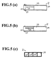
- Figs.5 (a), (b) and (c) are views facing arrow directions along, respectively, on a cross-section along line A-A of the fuse box of Fig.4 (a), a cross-section along line B-B of the fuse box of Fig.4, and a cross-section along line C-C of the fuse box of Fig.4 (b);
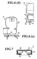
- Figs.6 (a), (b), (c), (d) and (e) show a fuse cover, seen respectively from, a top plan view, a front elevational view, a cross-sectional view along line D-D of Fig.6 (b), a side elevational view and a rear elevational view;
- Fig.7 is a view of the base face of the fuse cover of Fig.6; and
- Figs.8 (a), (b) and (c) are views of the fuse unit when contained in the fuse box, shown respectively by, a top plan view, a front elevational view and a side elevational view.
-
- Figs.2 to 8 show a
fuse unit 1 used in automobiles, according to an embodiment of the present invention. - As shown in Fig.2, the
fuse unit 1 is formed by incorporating an electricallyconductive plate 2, e.g. a metal plate. The latter 2 includes e.g. a material made of silver, copper, zinc, tin, lead, or an alloy made with at least one of these metals. Theconductive metal plate 2 is then formed into aninput terminal 3, one or several output terminals 4 (also known as "male tabs 4") and one or severalfuse element portions 5. Theinput terminal 3 can be directly connected to a power-supply terminal for a battery mounted in an automobile (not shown in the figures). This input terminal can therefore be qualified as a terminal directly connectable to a battery. Aninput terminal 3 comprises a first strip portion 3a (usually placed upright during use), and asecond strip portion 3b (usually placed horizontally during use) which is narrower than the first strip portion 3a and arranged perpendicular thereto. A first end (left-hand side in Fig.2 (c)) of thesecond strip portion 3b is linked to a first end (top side in Fig.2 (c)) of the first strip portion 3a. Thesecond strip portion 3b is configured so as to form a cross-section having an inverted U-shape (see top portion of Fig.2 (d)). A through hole 6 for bolt insertion is provided in thesecond strip portion 3b. It is placed at a half-way point widthwise and near a second end of thesecond strip portion 3b, distal to the first end thereof (see Fig.2 (a), in which thesecond strip portion 3b is shown in the upright position). Theinput terminal 3 is fixed to the power-supply terminal by fitting a bolt into the through hole 6 and a nut. - The
fuse unit 1 according to the present embodiment includes several units ofmale tabs 4 and correspondingfuse element portions 5. An example of the invention shown in Fig.2 contains four such units. Eachfuse element portion 5 contained in thecorresponding fuse unit 1 is made substantially narrower than themale tab 4, and wound into substantially a S-shaped configuration. A first end of eachfuse element portion 5 leads to the first end of thesecond strip portion 3b. A second end of thefuse element portion 5 leads to a first end (upper end in Fig.2 (b)) of themale tab 4, which extends in a vertical direction in the same figure. Theinput terminal 3 is thus connected to eachmale tab 4 through eachfuse element portion 5. - An peripheral area of the
fuse element portion 5 including the latter (which is formed in a conductive metal plate 2) is molded with an insulator resin. Such a peripheral area may cover the first strip portion 3a as a whole, and a top end portion of themale tab 4. The moldedresin portion 7 thus produced may form a thin plate. Typically, such an insulator resin includes an epoxy resin. The moldedresin portion 7 preferably includes fourwindow portions 8 at predetermined positions. Thewindow portions 8 may have a substantially square shape, as shown in Fig.2. Through thesewindow portion 8 is exposed eachfuse element portion 5 to the outside, beyond the moldedresin portion 7. Thefuse unit 1 of the present embodiment shown in Fig.2 is therefore in the form of a rake or fork. In this embodiment, oneinput terminal 3 branches into fourmale tabs 4. - The
fuse unit 1 is manufactured according to the steps shown in Fig.3 (a), (b) and (c). First, there is provided an initial electricallyconductive plate 2. Theconductive plate 2 is then stamped out to yield, integrally, aninput terminal 3, fourmale tabs 4 and corresponding tie bars 11. The tie bars 11 may have the same thickness as theconductive metal plate 2, but they may also be made thinner by, for example, half-etching. Preferably, eachtie bar 11 is formed at a position uncovered by the moldedresin portion 7, i.e. at a lower end portion of themale tab 4. Further, a through hole 6 for bolting (see Fig.2 (a)) may be formed at the same time as themetal plate 2 is stamped out. - The transformed
conductive plate 2 is then bent into a piece having a side cross-section of substantially L-shaped configuration, using a specific bending tool. An area including loci intended for subsequently lodging fuse element portions 5 (fuse-forming loci 12) is insert-molded in a suitable way with an insulator resin, so as to form a moldedresin portion 7. In a preferred embodiment, the insert-molding is effected such as to formwindow portions 8. In such a case, only the fuse-formingloci 12, intended for lodging thefuse element portions 5, are exposed to the outside through thewindow portions 8. In order to reserve room forwindow portions 8 in the moldedresin portion 7, the insert-molding die may be provided e.g. with a convexity corresponding to thewindow portions 8. - The exposed fuse-forming
loci 12 are then formed into fourfuse element portions 5 by stamping, whilst threetie bars 11 are removed by the same stamping operation. Themale tabs 4 are thus separated from each other to form a desiredfuse unit 1 shown in Fig.2. - The
fuse unit 1 thus produced is inserted into afuse box 21 shown in Fig.4, prior to use. Thefuse box 21 has a rectangular tubular shape, with top and bottom ends open. Atop opening 22 and abottom opening 24 thus have a rectangular surface, respectively. The outside rim portion of thetop opening 22 is provided with a plurality of stopper means 27 and aflat fixture portion 28. The inside space of thefuse box 21 is separated into four enclosures by threeinsulator partition walls 23. The top andbottom openings fuse box 21 are therefore defined by four square areas. The four enclosures form four spaces for containing terminals (not shown in the figures) to be press-fitted to an electrical cable. Preferably, a portion of the inner face offuse box 21, which inner face defines each of the four enclosures, is provided with a lance structure in order to hang the terminal therein. The other end of the terminal is press-fitted with a corresponding electrical cable which will constitute a wire harness. - A top portion of each
partition wall 23 is provided with aslit 25 which extends vertically from the top to a point half-way downwards. Theslits 25 have the same width for all the enclosures. The width of theslit 25 correspond to the thickness of the moldedresin portion 7 of thefuse unit 1, so that thefuse unit 1 is fixed in thefuse box 21 by inserting the moldedresin portion 7 into the slit 25 (see Fig.8). Two opposing positions on the smaller inner surfaces of thefuse box 21, which correspond to the cross points with a plane passing through theslits 25, are provided with a pair of guidingribs 26, respectively. The two guidingribs 26 of the same pair extend in parallel to each other, from top of thefuse box 21 to a point half-way downwards. The distance between the two guidingribs 26 is arranged to correspond substantially to the thickness of the moldedresin portion 7 of thefuse unit 1. Accordingly, when thefuse unit 1 is put into thefuse box 21, the two end rims of the moldedresin portion 7 are held by the two pairs of guiding ribs 26 (see Fig.8 (a)). - Figs.6 and 7 show a
fuse cover 41 for protecting thefuse unit 1. Thefuse cover 41 is made of an insulator material, e.g. a resin. Thefuse cover 41 comprises acover plate 42, a cover joint 43 and ahinge portion 44 combining them. Thecover plate 42 covers and protects the power-supply terminal for a battery mounted e.g. in an automobile. The outer side face of the top of thecover plate 42 is marked with an indication to caution that it encloses a power-supply terminal. The cover joint 43 is mounted so as to close thetop opening 22 of thefuse box 21. The cover joint 43 carries integrally formed hookingmeans 45 at positions corresponding to those of the stopper means 27. - Accordingly, when the
fuse cover 41 is placed on thefuse box 21, the hookingmeans 45 are hooked to the stopper means 27. The cover joint 43 is thus securely fixed onto thetop opening 22 of thefuse box 21. - There are provided two pairs of
cover guiding ribs 46 on the rear face the cover joint 43. The distance between thecover guiding ribs 46 is designed to be substantially the same as the thickness of the moldedresin portion 7 of thefuse unit 1. Accordingly, when thefuse unit 1 is installed and thefuse cover 41 is mounted, two end rims of the moldedresin portion 7 are held by the two pairs ofcover guiding ribs 46. - According to a manufacturing method of the invention, when
fuse element portions 5 are being formed, the peripheral area of the element-forming loci 12 (intended to form the fuse element portions 5) is already reinforced with a moldedresin portion 7. By virtue of this structure, even when narrowfuse element portions 5 are to be formed, they are less susceptible to stress which may otherwise cause curving or bending of the fuse elements. In other words, thefuse element portions 5 are more resistant to deformation or breaking, and maintain an appropriate strength during their manufacture. As a result, thefuse unit 1, however small their electric capacity is, can be manufactured relatively easily. - According to a method of the invention, four
fuse element portions 5 having different widths can be formed easily through one stamping die only. Costs incurred for preparing dies can thus be reduced to a minimum. As a consequence, thefuse units 1 and the entire assemblies containing thesefuse units 1 can be produced at low costs. - According to the present manufacturing method, the end portions of adjacent
male tabs 4 are initially linked to each other by tie bars 11. The structurally strengthening effect of this construction ensures that the mutual positions of themale tabs 4 are properly maintained, up to a moment when thefuse element portions 5 are formed by stamping. In addition, as mentioned above, thefuse element portions 5 are protected from stress which may cause a curving or bending of the fuse elements. Thefuse element portions 5 are thus less prone to deformation and breaking. - As has been understood from the above, the tie bars 11 can be removed at the same time as the
fuse element portions 5 are formed. The presence of the tie bars 11 does therefore not increase the operation steps as a whole, while enabling thefuses units 1 to be manufactured easily and efficiently. - Furthermore, since the stamping operation is effected on the loci exposed through the
window portions 8, the moldedresin portion 7 does not impede such operation. Thefuse element portions 5 can thus be formed very easily. - In the past, a plurality of individually manufactured fuse elements were fixed to a fuse unit. By comparison, according to the
inventive fuse unit 1, fourmale tabs 4 and fourfuse element portions 5 are formed in a same piece ofconductive metal plate 2. This construction obviates the need for a number of nuts and bolts, classically used for fixing the fuse element portions into afuse unit 1, as well as for fixing thefuse unit 1 into afuse box 21. Operators are thus freed from tedious operations of screwing bolts into nuts. In addition, fixing thefuse unit 1 into thefuse box 21 can be done much more easily than in the past. - In the
inventive fuse unit 1, the peripheral area of thefuse element portions 5, which tends to be mechanically weak, is protected by a moldedresin portion 7, so that thefuse unit 1 procures by itself a sufficient mechanical strength. In such construction, even if thefuse element portions 5 are rendered thin and narrow, they are not made susceptible of deformation as such. Furthermore, the presence of the moldedresin portion 7 makes thefuse unit 1 more waterproof. - Further, in the
fuse unit 1 of the invention, thefuse element portion 5 is constantly exposed to the outside through thewindow portion 8. Thefuse element portion 5 can thus be inspected visually, irrespective of the material used for the moldedresin portion 7. For example, when thefuse element portion 5 is fused by the passage of an excessive current, this condition is easily detected by human eye. - The structure of the
fuse unit 1 may be modified very easily, so as to produce variant embodiments as follows. - The number of
male tabs 4 used as output terminals is not limited to four, exemplified in the above embodiment. It may be one, two or three. It may also be more than four. The form ofmale tabs 4 may also be modified as desired. - Likewise, the
input terminal 3 may have a configuration other than the one described above, or may not include the through hole 6 for bolting. - When only one
male tab 4 is provided, the number offuse element portions 5 may also be reduced to one. - The insulator material used is not limited to the above-mentioned molded
resin portion 7, but may be e.g. rubber. Likewise, the insulator material may be formed according to a method other than the insert-molding. - When a rubber is used as insulator material, a
fuse element portion 5 can be formed by stamping, without forming thewindow portion 8. One reason for allowing such a formation step is that, as the rubber is a good elastic material, there forms little stress inside the rubber, and consequently no crack will be formed through such operation. - As mentioned above, the tie bars 11 may be removed at the same time as the
fuse element portion 5 is formed by stamping. But they may also be eliminated in a separate process. Moreover, when thefuse element portion 5 risks no deformation or breaking-up, the use of tie bars 11 may not be required. - Instead of stamping, the
fuse element portion 5 may also be formed by e.g. etching. - The
window portion 8 may be in a form other than a rectangular form, e.g. a circular or triangular form. Thewindow portion 8 may also be one single large unit including a plurality of fuse-formingloci 12, thereby forming onecommon window portion 8. - Further advantages of the present invention will be made apparent from the following description of the technical concepts on which the present invention is based.
- Firstly, the input terminal of the present invention can be connected directly to a power-supply terminal of batteries.
- Secondly, the input terminal of the invention can be used for the power-supply terminal for batteries in an automobile.
- Thirdly, each of the output terminals may be in the form of a male tab, which can be connected to a press-fixing terminal provided in a wire harness. According to this construction, the fuse unit can be connected to a wire harness in a very secured way.
- Fourthly, the fuse unit may be substantially in the shape of a rake or fork.
- Fifthly, the input terminal may be provided with a bolt hole, which may not be covered with the insulator material. By fixing with bolts, the input terminal can be fixed to the power-supply means in a more secured manner.
- Sixthly, the tie bars may be rendered thinner than the electrically conductive plate. The tie bars are thus very easily stamped away.
- Seventhly, the tie bars may be formed outside the area where the insulator material is coated. The tie bars can thus be eliminated, without removing the insulator material.
- Eighthly, the input terminal and the output terminals are first formed with the electrically conductive plate. An area of the conductive plate including the loci, where the fuse element portions should be formed later, is then molded with an insulator material. These loci for fuse element are subsequently transformed into fuse element portions. Accordingly, irrespective of their thickness, the fuse element portions can be formed at a predetermined position, in an easy and economical way.
- Ninthly, an area portion of the electrically conductive plate (which may include an input terminal, several output terminals and several fuse element portions linking them) is molded with an insulator material. In addition, the insulator material is provided with window portions, through which the fuse element portions are exposed to the outside. This fuse unit can be constructed easily and at a low cost. Further, the fuse unit obtained procures a sufficient mechanical strength, and can be easily mounted into a fuse box. Furthermore, the fuse element portions can be inspected by direct observation.
- A main advantage of the invention is that the fuse unit is manufactured in a easy and economical way, irrespective of the current capacity and number of the fuse element portions.
- A further advantage consists in the fact that the fuse element portions are protected from deformation or breaking while manufacturing the fuse unit.
- Another advantage is that, in a preferred embodiment, the fuse element portions can be inspected through a direct eye observation.
Claims (8)
- A method of forming a fuse unit (1) comprising an electrically conductive plate (2) including an input terminal (3), at least one output terminal (4) and at least one fuse element portion (5) linking the input terminal (3) and the output terminal(s) (4), the fuse unit further comprising an insulator material (7), characterised in that said method comprises the steps of:stamping said electrically conductive plate (2) so as to form said input terminal (3) and said output terminal(s) (4);providing at least one locus predetermined for forming said fuse element portion(s) (5);molding all or part of an area including said locus/loci with said insulator material (7); andforming said fuse element portion(s) (5) at said locus/loci.
- The method according to claim 1, wherein said molding step comprises molding a part of said area, such that at least one non-shielded portion is formed for said locus/loci.
- The method according to claim 2, wherein said molding step comprises insert-molding a part of said area by means of a die including at least one protrusion, so that said protrusion(s) form(s) said non-shielded portion(s).
- The method according to any one of claims 1 to 3, wherein said stamping step comprises stamping said electrically conductive plate (2) so as to form said input terminal (3), said output terminal(s) (4) having a respective end portion, and at least one tie bar (11) linking said end portion(s) of said output terminal(s) (4).
- The method according to claim 4, wherein said forming step comprises stamping said locus/loci so as to yield said fuse element portion(s) (5), whilst simultaneously removing said tie bar (s) (11) by said stamping.
- A fuse unit (1) comprising an electrically conductive plate (2) including an input terminal (3), at least one output terminal (4) and at least one fuse element portion (5) linking said input terminal (3) and said output terminal(s) (4), characterised in that said fuse unit (1) further comprises an area molded with an insulator material (7), and said area includes at least one opening (8), through which said fuse element portion(s) (5) can be exposed to outside said insulator material (7).
- A fuse box (21) containing a fuse unit (1), said fuse unit (1) comprising an electrically conductive plate (2) including an input terminal (3), at least one output terminal (4) and at least one fuse element portion (5) linking said input terminal (3) and said output terminal(s) (4), characterised in that:said fuse unit (1) further comprises an area molded with an insulator material (7), said area including at least one opening (8), through which said fuse element portion(s) (5) is/are exposed to outside said insulator material (7);said fuse box (21) forms a hollow cylindrical shape having a substantially rectangular cross-section, and a top opening (22) and a bottom opening (24), said fuse box (21) contains at least one partition wall (23) extending in the longitudinal direction of said cylindrical shape, thereby forming several enclosures lodging said output terminal(s) (4), said partition wall(s) (23) include(s) a slit (25) extending from said top opening (22) to a point half-way downwards in said longitudinal direction, and said slit(s) (25) lodge(s) said insulator material (7) such that said input terminal (3) extends perpendicularly to said longitudinal direction from said top opening (22).
- The fuse box (21) according to claim 7, further comprising a fuse cover (41) including a cover plate (42) and a cover joint (43), said cover plate covering said input terminal (3) of said fuse unit (1) and said cover joint (43) covering said top opening (22) of said fuse box (21).
Applications Claiming Priority (2)
| Application Number | Priority Date | Filing Date | Title |
|---|---|---|---|
| JP34535099A JP3814451B2 (en) | 1999-12-03 | 1999-12-03 | Manufacturing method of fuse |
| JP34535099 | 1999-12-03 |
Publications (3)
| Publication Number | Publication Date |
|---|---|
| EP1107275A2 true EP1107275A2 (en) | 2001-06-13 |
| EP1107275A3 EP1107275A3 (en) | 2002-07-31 |
| EP1107275B1 EP1107275B1 (en) | 2004-03-03 |
Family
ID=18376013
Family Applications (1)
| Application Number | Title | Priority Date | Filing Date |
|---|---|---|---|
| EP00403356A Expired - Lifetime EP1107275B1 (en) | 1999-12-03 | 2000-11-30 | Fuse unit and manufacturing method therefor |
Country Status (5)
| Country | Link |
|---|---|
| US (3) | US6566599B2 (en) |
| EP (1) | EP1107275B1 (en) |
| JP (1) | JP3814451B2 (en) |
| CN (1) | CN1199213C (en) |
| DE (1) | DE60008679T2 (en) |
Cited By (1)
| Publication number | Priority date | Publication date | Assignee | Title |
|---|---|---|---|---|
| US7176780B2 (en) | 2003-10-31 | 2007-02-13 | Yazaki Corporation | Fuse unit |
Families Citing this family (28)
| Publication number | Priority date | Publication date | Assignee | Title |
|---|---|---|---|---|
| JP4009515B2 (en) * | 2002-10-02 | 2007-11-14 | 矢崎総業株式会社 | Fusible link unit |
| DE10310122A1 (en) * | 2003-03-07 | 2004-09-16 | Siemens Ag | Electrical protection device and method of manufacture |
| JP2005216827A (en) * | 2004-02-02 | 2005-08-11 | Yazaki Corp | Electric wire terminal terminal and manufacturing method thereof |
| USD551174S1 (en) * | 2005-09-30 | 2007-09-18 | Pacific Engineering Corp. | Fuse |
| US20070236322A1 (en) * | 2006-04-10 | 2007-10-11 | Jerry Edwards | Fuse having connectable terminals |
| JP4769621B2 (en) * | 2006-04-18 | 2011-09-07 | 住友電装株式会社 | Bus bar housed in in-vehicle electrical junction box |
| JP4755018B2 (en) * | 2006-05-19 | 2011-08-24 | 矢崎総業株式会社 | Fusible link unit |
| DE102006024391A1 (en) * | 2006-05-24 | 2007-11-29 | Lisa Dräxlmaier GmbH | Motor vehicle safety unit, has bus bar comprising contact guides arranged in order to directly bring contact guides in conducting contact with external potential as plug geometry without interconnection of connecting outline |
| JP4805057B2 (en) * | 2006-08-04 | 2011-11-02 | 矢崎総業株式会社 | Fusible link unit |
| DE102006040824B4 (en) * | 2006-08-31 | 2013-03-28 | Lisa Dräxlmaier GmbH | Power distributor to compensate for a tolerance |
| US20080224814A1 (en) * | 2007-03-13 | 2008-09-18 | Lear Corporation | Electrical assembly and manufacturing method |
| JP2009056992A (en) * | 2007-09-03 | 2009-03-19 | Yazaki Corp | Protective cover mounting structure for the battery direct mounting fusible link unit |
| US7663466B1 (en) * | 2007-09-21 | 2010-02-16 | Yazaki North America, Inc. | Corner-mounted battery fuse |
| US8077007B2 (en) * | 2008-01-14 | 2011-12-13 | Littlelfuse, Inc. | Blade fuse |
| JP5207533B2 (en) | 2008-09-05 | 2013-06-12 | 矢崎総業株式会社 | Composite fusible link, fuse box and manufacturing method thereof |
| JP5266081B2 (en) * | 2009-02-06 | 2013-08-21 | 矢崎総業株式会社 | Fuse device and manufacturing method thereof |
| JP5486853B2 (en) * | 2009-06-29 | 2014-05-07 | 矢崎総業株式会社 | Fusible link unit |
| JP5346796B2 (en) * | 2009-12-24 | 2013-11-20 | 矢崎総業株式会社 | Fusible link unit |
| JP5402658B2 (en) * | 2010-01-14 | 2014-01-29 | 株式会社デンソー | Electronic equipment |
| JP5632672B2 (en) * | 2010-07-29 | 2014-11-26 | 矢崎総業株式会社 | Fuse unit |
| JP5682067B2 (en) | 2011-03-31 | 2015-03-11 | 矢崎総業株式会社 | Bus bar for fusible link block circuit configuration, fusible link block, and fusible link block manufacturing method |
| DE202011050310U1 (en) | 2011-05-31 | 2011-07-11 | Lisa Dräxlmaier GmbH | Angled midi or fuse |
| WO2012164884A1 (en) | 2011-05-31 | 2012-12-06 | パナソニック株式会社 | Fuse board and battery block equipped with same |
| JP6007012B2 (en) * | 2012-07-23 | 2016-10-12 | 矢崎総業株式会社 | Fuse unit |
| JP6018937B2 (en) | 2013-01-29 | 2016-11-02 | 三洋電機株式会社 | Electrode member and battery block |
| JP6373893B2 (en) * | 2016-04-06 | 2018-08-15 | 太平洋精工株式会社 | FUSE UNIT AND FUSE UNIT MANUFACTURING METHOD |
| US11049680B2 (en) * | 2017-09-08 | 2021-06-29 | Littelfuse, Inc. | Low profile integrated fuse module |
| JP7772750B2 (en) * | 2023-08-28 | 2025-11-18 | 矢崎総業株式会社 | Electrical connection structure |
Family Cites Families (38)
| Publication number | Priority date | Publication date | Assignee | Title |
|---|---|---|---|---|
| US3093767A (en) * | 1961-05-10 | 1963-06-11 | Gen Electric | Gas generating switching tube |
| US3829808A (en) * | 1973-02-14 | 1974-08-13 | Westinghouse Electric Corp | Fuse housing construction utilizing extruded terminals and process for making same |
| US3775723A (en) * | 1973-03-05 | 1973-11-27 | Gen Motors Corp | Circuit protector |
| US4056884A (en) * | 1975-02-08 | 1977-11-08 | Littelfuse, Inc. | Method of making a miniature plug-in fuse |
| US4504816A (en) * | 1983-10-31 | 1985-03-12 | Parker-Hannifin Corporation | Blade fuse and manufacturing method |
| US4531806A (en) * | 1983-11-25 | 1985-07-30 | General Motors Corporation | Fusible electrical connector |
| US4563666A (en) * | 1984-06-04 | 1986-01-07 | Littelfuse, Inc. | Miniature fuse |
| US4608548A (en) * | 1985-01-04 | 1986-08-26 | Littelfuse, Inc. | Miniature fuse |
| US4672352A (en) * | 1986-04-23 | 1987-06-09 | Kabushiki Kaisha T An T | Fuse assembly |
| US4689597A (en) * | 1986-04-29 | 1987-08-25 | Amp Incorporated | Electrical fuse component and method of using same |
| US4773157A (en) * | 1986-04-29 | 1988-09-27 | Amp Incorporated | Method of making an electrical termination |
| JPH0766734B2 (en) * | 1987-09-01 | 1995-07-19 | 矢崎総業株式会社 | Fuse manufacturing method |
| US4884050A (en) * | 1988-07-18 | 1989-11-28 | Kozel Emmett L | Blade terminal tap fuse |
| US5171293A (en) * | 1991-12-05 | 1992-12-15 | Yazaki Corporation | Fuse box assembly |
| US5229739A (en) * | 1992-02-21 | 1993-07-20 | Littelfuse, Inc. | Automotive high current fuse |
| JPH05299003A (en) | 1992-04-23 | 1993-11-12 | Yazaki Corp | Fusible link |
| JP2879811B2 (en) * | 1993-07-02 | 1999-04-05 | 矢崎総業株式会社 | Intermittent mechanism of dark current fuse and electric junction box provided with the same |
| US5346411A (en) * | 1993-12-13 | 1994-09-13 | Nikkinen Kurt D | Tap-in blade fuse |
| JPH087743A (en) * | 1994-06-15 | 1996-01-12 | Yazaki Corp | Fusible link and assembling method thereof |
| US5790007A (en) * | 1995-03-23 | 1998-08-04 | Sumitomo Wiring Systems, Ltd. | Board fuse, and method of manufacturing the board fuse |
| US5645448A (en) * | 1995-10-16 | 1997-07-08 | Yazaki Corporation | Battery connecting module with fuse mounting |
| JP3573313B2 (en) * | 1995-10-17 | 2004-10-06 | 矢崎総業株式会社 | Fusible link |
| US5841338A (en) * | 1996-04-17 | 1998-11-24 | Sumitomo Wiring Systems, Ltd. | Fuse combination, method of making the same, and fuse circuit including the same |
| US5818320A (en) * | 1996-10-08 | 1998-10-06 | Yazaki Corporation | Fuse assembly with removable fusible element |
| JPH10125213A (en) * | 1996-10-18 | 1998-05-15 | Yazaki Corp | Arcless fuse |
| JP3242849B2 (en) * | 1996-10-30 | 2001-12-25 | 矢崎総業株式会社 | High current fuse unit |
| DE19646264C2 (en) * | 1996-11-09 | 2000-10-26 | Wilhelm Pudenz Gmbh Elektrotec | Fusible conductor structure |
| JPH10199396A (en) * | 1997-01-13 | 1998-07-31 | Taiheiyo Seiko Kk | Multi-pole type fuse element and multi-pole type fuse using this element |
| US5783985A (en) * | 1997-04-25 | 1998-07-21 | Littelfuse, Inc. | Compressible body for fuse |
| US5886612A (en) * | 1997-10-20 | 1999-03-23 | Littelfuse, Inc. | Female fuse housing |
| EP0924734B1 (en) * | 1997-12-17 | 2003-11-12 | Meccanotecnica Codognese S.p.A. | A high-current protection device |
| JP3719475B2 (en) * | 1998-01-20 | 2005-11-24 | 矢崎総業株式会社 | High current fuse |
| JP2000164111A (en) * | 1998-03-16 | 2000-06-16 | Yazaki Corp | High current fuse for automobile |
| JP3810212B2 (en) * | 1998-05-19 | 2006-08-16 | 矢崎総業株式会社 | Large current fuse with temperature detection function and assembly method thereof |
| US6111758A (en) * | 1998-06-19 | 2000-08-29 | Scientific-Atlanta, Inc. | Electronic component having alternate functionalities |
| JP4181662B2 (en) | 1998-07-10 | 2008-11-19 | 太平洋精工株式会社 | Multipolar fuse element |
| JP2000113803A (en) * | 1998-10-01 | 2000-04-21 | Yazaki Corp | High current fuse for automobile |
| JP4096431B2 (en) * | 1998-12-11 | 2008-06-04 | 太平洋精工株式会社 | Multiple fuse element and multiple fuse using the multiple fuse element |
-
1999
- 1999-12-03 JP JP34535099A patent/JP3814451B2/en not_active Expired - Fee Related
-
2000
- 2000-11-30 DE DE60008679T patent/DE60008679T2/en not_active Expired - Lifetime
- 2000-11-30 EP EP00403356A patent/EP1107275B1/en not_active Expired - Lifetime
- 2000-12-01 US US09/726,335 patent/US6566599B2/en not_active Expired - Fee Related
- 2000-12-02 CN CNB001280929A patent/CN1199213C/en not_active Expired - Fee Related
-
2002
- 2002-01-22 US US10/051,361 patent/US6580032B2/en not_active Expired - Fee Related
- 2002-11-27 US US10/304,864 patent/US6624356B2/en not_active Expired - Fee Related
Non-Patent Citations (1)
| Title |
|---|
| None |
Cited By (2)
| Publication number | Priority date | Publication date | Assignee | Title |
|---|---|---|---|---|
| US7176780B2 (en) | 2003-10-31 | 2007-02-13 | Yazaki Corporation | Fuse unit |
| DE102004052476B4 (en) * | 2003-10-31 | 2007-08-09 | Yazaki Corp. | fuse assembly |
Also Published As
| Publication number | Publication date |
|---|---|
| US20020058441A1 (en) | 2002-05-16 |
| US6624356B2 (en) | 2003-09-23 |
| EP1107275A3 (en) | 2002-07-31 |
| CN1199213C (en) | 2005-04-27 |
| JP3814451B2 (en) | 2006-08-30 |
| US20010002812A1 (en) | 2001-06-07 |
| US6566599B2 (en) | 2003-05-20 |
| US6580032B2 (en) | 2003-06-17 |
| EP1107275B1 (en) | 2004-03-03 |
| CN1299145A (en) | 2001-06-13 |
| JP2001160347A (en) | 2001-06-12 |
| DE60008679D1 (en) | 2004-04-08 |
| US20030075352A1 (en) | 2003-04-24 |
| DE60008679T2 (en) | 2005-03-03 |
Similar Documents
| Publication | Publication Date | Title |
|---|---|---|
| EP1107275B1 (en) | Fuse unit and manufacturing method therefor | |
| US8721367B2 (en) | Fuse unit | |
| EP1336978B1 (en) | Blade fuse | |
| JP6653121B2 (en) | Electrical junction box | |
| US8077007B2 (en) | Blade fuse | |
| US7990738B2 (en) | Master fuse module | |
| JP4211589B2 (en) | Fusible link and battery fuse unit containing fusible link | |
| KR101370196B1 (en) | Fusible link unit | |
| JP6510482B2 (en) | Fixing structure of conductor unit | |
| US7413488B2 (en) | Wire end terminal and method of producing same | |
| EP1107276B1 (en) | Fuse box device | |
| CN1165390A (en) | Fuse combination, method of making the same, and fuse circuit including the same | |
| JPH1040986A (en) | Male terminal fitting | |
| JP2017157276A (en) | Wiring module | |
| JP3498658B2 (en) | Fuse box unit | |
| US20260142114A1 (en) | Fuse module | |
| US20170032919A1 (en) | Fusible link unit | |
| JP2024027390A (en) | Fuse unit and fuse unit assembly method | |
| JP2025008362A (en) | Fuse Unit | |
| CN119137815A (en) | Cover structure for junction box | |
| JPH0847138A (en) | Connection structure of electrical junction box | |
| JP2003061228A (en) | Automotive electrical junction box | |
| JPH0348639B2 (en) | ||
| JP2017097954A (en) | Electric wire with terminal fitting |
Legal Events
| Date | Code | Title | Description |
|---|---|---|---|
| PUAI | Public reference made under article 153(3) epc to a published international application that has entered the european phase |
Free format text: ORIGINAL CODE: 0009012 |
|
| 17P | Request for examination filed |
Effective date: 20001208 |
|
| AK | Designated contracting states |
Kind code of ref document: A2 Designated state(s): AT BE CH CY DE DK ES FI FR GB GR IE IT LI LU MC NL PT SE TR |
|
| AX | Request for extension of the european patent |
Free format text: AL;LT;LV;MK;RO;SI |
|
| PUAL | Search report despatched |
Free format text: ORIGINAL CODE: 0009013 |
|
| AK | Designated contracting states |
Kind code of ref document: A3 Designated state(s): AT BE CH CY DE DK ES FI FR GB GR IE IT LI LU MC NL PT SE TR |
|
| AX | Request for extension of the european patent |
Free format text: AL;LT;LV;MK;RO;SI |
|
| RIC1 | Information provided on ipc code assigned before grant |
Free format text: 7H 01H 85/044 A |
|
| AKX | Designation fees paid |
Designated state(s): DE FR GB IT |
|
| GRAP | Despatch of communication of intention to grant a patent |
Free format text: ORIGINAL CODE: EPIDOSNIGR1 |
|
| GRAS | Grant fee paid |
Free format text: ORIGINAL CODE: EPIDOSNIGR3 |
|
| GRAA | (expected) grant |
Free format text: ORIGINAL CODE: 0009210 |
|
| AK | Designated contracting states |
Kind code of ref document: B1 Designated state(s): DE FR GB IT |
|
| REG | Reference to a national code |
Ref country code: GB Ref legal event code: FG4D |
|
| REG | Reference to a national code |
Ref country code: IE Ref legal event code: FG4D |
|
| REF | Corresponds to: |
Ref document number: 60008679 Country of ref document: DE Date of ref document: 20040408 Kind code of ref document: P |
|
| ET | Fr: translation filed | ||
| PLBE | No opposition filed within time limit |
Free format text: ORIGINAL CODE: 0009261 |
|
| STAA | Information on the status of an ep patent application or granted ep patent |
Free format text: STATUS: NO OPPOSITION FILED WITHIN TIME LIMIT |
|
| 26N | No opposition filed |
Effective date: 20041206 |
|
| PG25 | Lapsed in a contracting state [announced via postgrant information from national office to epo] |
Ref country code: IT Free format text: LAPSE BECAUSE OF NON-PAYMENT OF DUE FEES;WARNING: LAPSES OF ITALIAN PATENTS WITH EFFECTIVE DATE BEFORE 2007 MAY HAVE OCCURRED AT ANY TIME BEFORE 2007. THE CORRECT EFFECTIVE DATE MAY BE DIFFERENT FROM THE ONE RECORDED. Effective date: 20051130 |
|
| PGFP | Annual fee paid to national office [announced via postgrant information from national office to epo] |
Ref country code: DE Payment date: 20121128 Year of fee payment: 13 Ref country code: FR Payment date: 20121130 Year of fee payment: 13 |
|
| PGFP | Annual fee paid to national office [announced via postgrant information from national office to epo] |
Ref country code: GB Payment date: 20121128 Year of fee payment: 13 |
|
| REG | Reference to a national code |
Ref country code: DE Ref legal event code: R119 Ref document number: 60008679 Country of ref document: DE |
|
| GBPC | Gb: european patent ceased through non-payment of renewal fee |
Effective date: 20131130 |
|
| REG | Reference to a national code |
Ref country code: FR Ref legal event code: ST Effective date: 20140731 |
|
| PG25 | Lapsed in a contracting state [announced via postgrant information from national office to epo] |
Ref country code: DE Free format text: LAPSE BECAUSE OF NON-PAYMENT OF DUE FEES Effective date: 20140603 |
|
| REG | Reference to a national code |
Ref country code: DE Ref legal event code: R119 Ref document number: 60008679 Country of ref document: DE Effective date: 20140603 |
|
| PG25 | Lapsed in a contracting state [announced via postgrant information from national office to epo] |
Ref country code: FR Free format text: LAPSE BECAUSE OF NON-PAYMENT OF DUE FEES Effective date: 20131202 Ref country code: GB Free format text: LAPSE BECAUSE OF NON-PAYMENT OF DUE FEES Effective date: 20131130 |