EP1107271B1 - Pôle de disjoncteur à commande unipolaire - Google Patents
Pôle de disjoncteur à commande unipolaire Download PDFInfo
- Publication number
- EP1107271B1 EP1107271B1 EP00403323A EP00403323A EP1107271B1 EP 1107271 B1 EP1107271 B1 EP 1107271B1 EP 00403323 A EP00403323 A EP 00403323A EP 00403323 A EP00403323 A EP 00403323A EP 1107271 B1 EP1107271 B1 EP 1107271B1
- Authority
- EP
- European Patent Office
- Prior art keywords
- casing
- pole
- fixed
- feet
- assembly
- Prior art date
- Legal status (The legal status is an assumption and is not a legal conclusion. Google has not performed a legal analysis and makes no representation as to the accuracy of the status listed.)
- Expired - Lifetime
Links
Images


Classifications
-
- H—ELECTRICITY
- H01—ELECTRIC ELEMENTS
- H01H—ELECTRIC SWITCHES; RELAYS; SELECTORS; EMERGENCY PROTECTIVE DEVICES
- H01H33/00—High-tension or heavy-current switches with arc-extinguishing or arc-preventing means
- H01H33/02—Details
- H01H33/42—Driving mechanisms
Definitions
- the present invention relates to a unipolar control circuit breaker pole comprising an interrupting chamber connected to an insulating column whose lower end is fixed to a metal casing of a face from which a rotary shaft for actuating the pole, the assembly being attached to a support and comprising a mechanical control unit having an output shaft control.
- the metal casing is protected by a cover to which is fixed the control box.
- the assembly is fixed by the lower end of the housing to a support having feet connected to a plate.
- the assembly constituted by the interrupting chamber, the insulating column and the metal casing is assembled at the factory and it is on the site that this assembly is fixed to the support and that the control box is fixed to the hood. crankcase protection and that the shafts are coupled.
- the present invention provides a different structure as well as a different implementation method.
- the proposed solution is simpler, more economical.
- the support and the casing participate reciprocally to their respective rigidity.
- the object of the invention is therefore a unipolar control circuit-breaker pole comprising an interrupting chamber connected to an insulating column, the lower end of which is fixed to a metal casing on one side of which a rotary shaft for actuating the pole emerges.
- the assembly being attached to a support and comprising a mechanical control unit having an output shaft, characterized in that said support consists of independent feet of each other and each fixed directly to said metal casing in at least two points respectively at the upper part and the lower part of said housing.
- the invention also relates to a method of setting up such a circuit breaker pole, characterized in that the assembly formed by the breaking chamber, the insulating column, the metal casing and said mechanical control box is assembled. and set at the factory, then transported to the site, in that, on this assembly disposed horizontally, said feet are mounted and in that, with a lifting means, the assembly is raised vertically and is flanged to soil the feet.
- the subject of the invention is also an assembly comprising a unipolar circuit-breaker pole breaking chamber, an insulating column connected to the breaking chamber, a metal casing with a face from which a rotary shaft for actuating the pole comes out, attached to the lower end of the insulating column and a mechanical control unit having an output shaft characterized in that said control unit is fixed to said metal housing, directly or via an adapter piece and in that said metal casing comprises means located in the upper part and in the lower part of the casing to be able to fix on the site of the support legs.
- FIG. 1 is a general view of the circuit breaker pole according to the invention.
- Fig. 2 shows, in detached perspective view, the metal housing fixed at the foot of the pole.
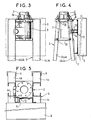
- Figs. 3, 4 and 5 show, in three views, at the housing, the arrangement connecting the control box and the feet to the housing.
- FIG. 3 the mechanical control box is only shown in dotted lines and without the adapter piece
- FIG. 5 is a top view without the cut-off chamber and insulating column assembly.
- a pole of unipolar circuit breaker according to the invention. It comprises a breaking chamber 1 connected to an insulating column 2 whose lower end is fixed to a support 4 which rests on the ground to which it is fixed by flanges 5 at the bottom of the support.
- the support 4 consists of simple legs 4a, 4b, 4c and 4d, completely independent of each other and fixed, each directly on the casing 3 in the upper part and in the lower part: on the upper flange 10 and the lower flange 11
- the pole is actuated by a mechanical control unit 6 fixed directly or via an adapter piece 7 to the metal casing 3 as shown in FIGS. 3 to 5.
- This adaptation piece 7 can moreover be an integral part of the control box 6.
- control unit 6 is thus fixed, directly, via the adaptation piece 7 to the metal casing 3 by screws 8 which are fixed in threaded holes 9 of the upper flange 10 and the lower flange 11 of the metal housing 3.
- the control unit 6 has at the output a control shaft 12 visible in dotted line. 4.
- the metal housing 3 comprises at the outlet, through the orifice referenced 13 in FIG. 2 showing the housing 3 in isolation, a rotary shaft 14 for actuating the pole.
- This rotary shaft 14 is visible in dotted line. 4.
- the control box 6 is fixed to the metal housing 3 so that the control shaft 12 and the rotary shaft 14 are coaxial.
- a coupling sleeve 15 connects the two shafts 12 and 14. It is for example a splined sleeve connecting two splined shafts.
- the insulating column 2 comprises at its lower end a flange 16 for attachment to the upper flange 10 of the metal casing 3.
- the assembly formed by the breaking chamber 1, the insulating column 2, the metal casing 3 and the mechanical control box 6 is assembled and adjusted at the factory.
- the upper and lower flanges 11 could be triangular and there would be only three feet.
- This structure where the support 4 consists only of the independent feet of each other and fixed directly to the metal casing 3 at a high point and at a low point of the casing ensures both a stiffening of the casing and excellent performance for the feet. Indeed, this fixing feet in two points is equivalent to a recess. The mechanical strength buckling is excellent.
Landscapes
- Driving Mechanisms And Operating Circuits Of Arc-Extinguishing High-Tension Switches (AREA)
- Patch Boards (AREA)
- Train Traffic Observation, Control, And Security (AREA)
- Interface Circuits In Exchanges (AREA)
Description
- La présente invention concerne un pôle de disjoncteur à commande unipolaire comprenant une chambre de coupure liée à une colonne isolante dont l'extrémité inférieure est fixée à un carter métallique d'une face duquel sort un arbre rotatif d'actionnement du pôle, l'ensemble étant fixé à un support et comprenant un boîtier de commande mécanique comportant en sortie un arbre de commande.
- Le document FR 2 719 153 décrit un tel pôle de disjoncteur.
- Dans ce document, le carter métallique est protégé par un capot auquel est fixé le boîtier de commande.
- Par ailleurs l'ensemble est fixé par l'extrémité inférieure du carter à un support comportant des pieds liés à un plateau.
- Dans les installations connues, l'ensemble constitué par la chambre de coupure, la colonne isolante et le carter métallique est assemblé en usine et c'est sur le site que cet ensemble est fixé au support et que le boîtier de commande est fixé au capot de protection du carter et que l'accouplement des arbres est effectué.
- La présente invention propose une structure différente ainsi qu'un procédé de mise en place différent. La solution proposée est plus simple, plus économique. Le support et le carter participent réciproquement à leur rigidité respective.
- L'invention a ainsi pour objet un pôle de disjoncteur à commande unipolaire comportant une chambre de coupure liée à une colonne isolante dont l'extrémité inférieure est fixée à un carter métallique d'une face duquel sort un arbre rotatif d'actionnement du pôle, l'ensemble étant fixé à un support et comprenant un boîtier de commande mécanique comportant en sortie un arbre de commande, caractérisé en ce que ledit support est constitué de pieds indépendants les uns des autres et fixés chacun directement sur ledit carter métallique en au moins deux points situés respectivement à la partie supérieure et à la partie inférieure dudit carter.
- L'invention a aussi pour objet un procédé de mise en place d'un tel pôle de disjoncteur, caractérisé en ce que l'ensemble formé par la chambre de coupure, la colonne isolante, le carter métallique et ledit boîtier de commande mécanique est assemblé et réglé en usine, puis transporté sur le site, en ce que, sur cet ensemble disposé horizontalement, on monte lesdits pieds et en ce que, avec un moyen de levage, on relève l'ensemble à la verticale et l'on bride au sol les pieds.
- L'invention a encore pour objet un ensemble comportant une chambre de coupure de pôle de disjoncteur à commande unipolaire, une colonne isolante liée à la chambre de coupure, un carter métallique d'une face duquel sort un arbre rotatif d'actionnement du pôle, fixé à l'extrémité inférieure de la colonne isolante et un boîtier de commande mécanique comportant en sortie un arbre de commande caractérisé en ce que ledit boîtier de commande est fixé audit carter métallique, directement ou par l'intermédiaire d'une pièce d'adaptation et en ce que ledit carter métallique comporte des moyens situés en partie haute et en partie basse du carter pour pouvoir y fixer sur le site des pieds supports.
- On va maintenant donner la description d'un exemple de mise en oeuvre de l'invention en se reportant au dessin annexé dans lequel la Fig. 1 est une vue générale du pôle de disjoncteur selon l'invention.
- La Fig. 2 montre, en vue détachée en perspective, le carter métallique fixé en pied de pôle.
- Les Fig. 3, 4 et 5 montrent, selon trois vues, au niveau du carter, l'agencement reliant le boîtier de commande et les pieds au carter.
- Sur la Fig. 3, le boîtier de commande mécanique n'est que figuré en trait mixte et sans la pièce d'adaptation, et la Fig. 5 est une vue de dessus sans l'ensemble chambre de coupure et colonne isolante.
- En se référant aux figures, on voit un pôle de disjoncteur à commande unipolaire selon l'invention. Il comprend une chambre de coupure 1 liée à une colonne isolante 2 dont l'extrémité inférieure est fixée à un support 4 qui repose sur le sol auquel il est fixé par des brides 5 en pied du support. Le support 4 est constitué de simples pieds 4a, 4b, 4c et 4d, complètement indépendants les uns des autres et fixés, chacun, directement sur le carter 3 en partie haute et en partie basse : sur la bride supérieure 10 et la bride inférieure 11 du carter par des vis 20 dans des trous taraudés 21. Le pôle est manoeuvré par un boîtier de commande mécanique 6 fixé directement ou par l'intermédiaire d'une pièces d'adaptation 7 sur le carter métallique 3 comme le montrent bien les Fig. 3 à 5. Cette pièce d'adaptation 7 peut d'ailleurs faire partie intégrante du boîtier de commande 6.
- Le boîtier de commande 6 est ainsi fixé, directement, par l'intermédiaire de la pièce d'adaptation 7 au carter métallique 3 par des vis 8 venant se fixer dans des trous taraudés 9 de la bride supérieure 10 et de la bride inférieure 11 du carter métallique 3.
- Le boîtier de commande 6 comporte en sortie un arbre de commande 12 visible en pointillé Fig. 4. De la même façon, le carter métallique 3 comporte en sortie, par l'orifice référencé 13 sur la Fig. 2 montrant le carter 3 isolément, un arbre rotatif 14 d'actionnement du pôle. Cet arbre rotatif 14 est visible en pointillé Fig. 4. Comme on le voit sur cette Fig. 4, le boîtier de commande 6 est fixé au carter métallique 3 de telle sorte que l'arbre de commande 12 et l'arbre rotatif 14 soient coaxiaux. Un manchon d'accouplement 15 relie les deux arbres 12 et 14. Il s'agit par exemple d'un manchon cannelé reliant deux arbres à cannelures. On pourrait également avoir un arbre mâle et un autre femelle ou tout autre moyen d'accouplement. La colonne isolante 2 comporte à son extrémité inférieure une bride 16 pour sa fixation sur la bride supérieure 10 du carter métallique 3.
- L'ensemble constitué par la chambre de coupure 1, la colonne isolante 2, le carter métallique 3 et le boîtier de commande mécanique 6, est assemblé et réglé en usine.
- Ce n'est que sur le site que l'on vient fixer à cet ensemble les pieds supports 4a, 4b, 4c et 4d. Ces pieds sont à section en U.
- Une fois ledit ensemble transporté sur le site, on le dispose horizontalement et l'on vient fixer ces quatre pieds au carter métallique 3, sur la bride supérieure 10 et la bride inférieure 11 sur leurs deux faces 17a, 17b et 18a, 18b perpendiculaires aux faces 19a, 19b contre lesquelles a été fixé le boîtier de commande 6, au moyen des vis 20 dans les trous taraudés 21 du carter 3.
- Ceci fait, on relève l'ensemble à la verticale, avec un moyen de levage et on le fixe au sol par les brides 5 aux extrémités des pieds.
- On voit donc que le montage sur le site est très simplifié, le boîtier de commande 6 ayant été fixé directement au carter 3, préalablement en usine, avec le réglage de l'accouplement des deux arbres 12 et 14 également effectués en usine.
- On pourrait concevoir un nombre de pieds différent. Par exemple, les brides supérieure 10 et inférieure 11 pourraient être triangulaires et l'on n'aurait que trois pieds.
- Cette structure où le support 4 n'est constitué que des pieds indépendants les uns des autres et fixés directement au carter métallique 3 en un point haut et en un point bas du carter assure à la fois une rigidification du carter et une excellente tenue pour les pieds. En effet cette fixation des pieds en deux points est équivalente à un encastrement. La tenue mécanique au flambage est excellente.
- La fixation directe du boîtier de commande 6 au carter 3 participe également à la rigidification mutellle du carter et du boîtier de commande. La structure de l'ensemble est très simple et il n'y a plus de capot entourant le carter comme dans le document antérieur cité.
Claims (4)
- Pôle de disjoncteur à commande unipolaire comportant une chambre de coupure (1) liée à une colonne isolante (2) dont l'extrémité inférieure est fixée à un carter métallique (3) d'une face duquel sort un arbre rotatif (14) d'actionnement du pôle, l'ensemble étant fixé à un support et comprenant un boîtier de commande mécanique (6) comportant en sortie un arbre de commande (12), caractérisé en ce que ledit support (4) est constitué de pieds (4a à 4d) indépendants les uns des autres et fixés chacun directement sur ledit carter métallique (3) en au moins deux points situés respectivement à la partie supérieure et à la partie inférieure dudit carter.
- Pôle de disjoncteur selon la revendication 1, caractérisé en ce que ledit boîtier de commande est fixé audit carter métallique (3), directement ou par l'intermédiaire d'une pièce d'adaptation (7)..
- Procédé de mise en place d'un pôle de disjoncteur selon la revendication 2, caractérisé en ce que l'ensemble formé par la chambre de coupure (1), la colonne isolante (2), le carter métallique (3) et ledit boîtier de commande mécanique (6), est assemblé et réglé en usine, puis transporté sur le site, en ce que, sur cet ensemble disposé horizontalement, on monte lesdits pieds (4a à 4d) et en ce que, avec un moyen de levage, on relève l'ensemble à la verticale et l'on bride au sol les pieds (4a à 4d).
- Ensemble comportant une chambre de coupure (1) de pôle de disjoncteur à commande unipolaire, une colonne isolante (2) liée à la chambre de coupure, un carter métallique (3) d'une face duquel sort un arbre rotatif (14) d'actionnement du pôle, fixé à l'extrémité inférieure de la colonne isolante et un boîtier de commande mécanique (6) comportant en sortie un arbre de commande (12) caractérisé en ce que ledit boîtier de commande est fixé audit carter métallique (3), directement ou par l'intermédiaire d'une pièce d'adaptation (7) et en ce que ledit carter métallique (3) comporte des moyens (21) situés en partie haute (10) et en partie basse (11) du carter (3) pour pouvoir y fixer sur le site des pieds supports.
Applications Claiming Priority (2)
| Application Number | Priority Date | Filing Date | Title |
|---|---|---|---|
| FR9915499 | 1999-12-08 | ||
| FR9915499A FR2802331B1 (fr) | 1999-12-08 | 1999-12-08 | Pole de disjoncteur a commande unipolaire |
Publications (2)
| Publication Number | Publication Date |
|---|---|
| EP1107271A1 EP1107271A1 (fr) | 2001-06-13 |
| EP1107271B1 true EP1107271B1 (fr) | 2006-06-21 |
Family
ID=9553034
Family Applications (1)
| Application Number | Title | Priority Date | Filing Date |
|---|---|---|---|
| EP00403323A Expired - Lifetime EP1107271B1 (fr) | 1999-12-08 | 2000-11-28 | Pôle de disjoncteur à commande unipolaire |
Country Status (4)
| Country | Link |
|---|---|
| EP (1) | EP1107271B1 (fr) |
| AT (1) | ATE331294T1 (fr) |
| DE (1) | DE60028911T2 (fr) |
| FR (1) | FR2802331B1 (fr) |
Families Citing this family (1)
| Publication number | Priority date | Publication date | Assignee | Title |
|---|---|---|---|---|
| CN117174525B (zh) * | 2023-09-21 | 2024-04-02 | 西门子能源高压开关(杭州)有限公司 | 用于罐式断路器的支架组件和该组件的运输和组装方法 |
Family Cites Families (3)
| Publication number | Priority date | Publication date | Assignee | Title |
|---|---|---|---|---|
| CH356182A (de) * | 1956-12-14 | 1961-08-15 | Siemens Ag | Hochspannungsschalter |
| DE8705155U1 (de) * | 1987-04-07 | 1988-08-04 | Siemens AG, 1000 Berlin und 8000 München | Hochspannungs-Leistungsschalter, insbesondere Druckgas-Leistungsschalter |
| FR2719153B1 (fr) * | 1994-04-21 | 1996-05-24 | Gec Alsthom T & D Sa | Liaison entre un pôle de disjoncteur et sa commande. |
-
1999
- 1999-12-08 FR FR9915499A patent/FR2802331B1/fr not_active Expired - Fee Related
-
2000
- 2000-11-28 EP EP00403323A patent/EP1107271B1/fr not_active Expired - Lifetime
- 2000-11-28 DE DE60028911T patent/DE60028911T2/de not_active Expired - Lifetime
- 2000-11-28 AT AT00403323T patent/ATE331294T1/de not_active IP Right Cessation
Also Published As
| Publication number | Publication date |
|---|---|
| DE60028911D1 (de) | 2006-08-03 |
| FR2802331B1 (fr) | 2002-02-01 |
| DE60028911T2 (de) | 2007-01-18 |
| ATE331294T1 (de) | 2006-07-15 |
| FR2802331A1 (fr) | 2001-06-15 |
| EP1107271A1 (fr) | 2001-06-13 |
Similar Documents
| Publication | Publication Date | Title |
|---|---|---|
| EP2488379B1 (fr) | Cadre moteur pour moteur electrique de vehicule automobile | |
| EP2409553B1 (fr) | Ensemble de commande comportant un variateur de vitesse et un disjoncteur | |
| FR2711019A1 (fr) | Armoire à appareils. | |
| EP3323175B1 (fr) | Dispositif de connexion électrique raccordable à plusieurs câbles avec protection contre les dommages par corps étrangers | |
| FR2950202A1 (fr) | Coffret destine a recevoir un appareillage electrique basse tension associe a une cellule electrique moyenne tension | |
| EP1107271A1 (fr) | Pôle de disjoncteur à commande unipolaire | |
| FR2945830A3 (fr) | Serrure electromagnetique | |
| FR2800905A1 (fr) | Interrupteur de centrale avec un echangeur-radiateur | |
| FR2655215A1 (fr) | Boitier porte-bornes modulaire a appliquer a des servomoteurs electriques pour la commande de soupapes. | |
| BE1005448A6 (fr) | Appareil d'eclairage. | |
| FR2721363A1 (fr) | Dispositif de fixation. | |
| FR2501959A1 (fr) | Tondeuse a gazon rotative comportant a l'arriere un montage protege-pieds | |
| CH350341A (fr) | Cellule préfabriquée destinée à une installation de transport d'énergie | |
| EP0533591B1 (fr) | Châssis d'appareillage, notamment pour coffret électrique | |
| FR2695792A1 (fr) | Ensemble pour appareils électroniques de commande et procédé de fabrication pour la mise en Óoeuvre de cet ensemble. | |
| FR2609574A1 (fr) | Support de dispositif de rearmement de disjoncteur | |
| EP2713435B1 (fr) | Système de montage d'une antenne sur un support cylindrique | |
| BE1000383A6 (fr) | Appareil de commande et de reglage, en particulier pour installations de chauffage. | |
| FR2517486A1 (fr) | Poste electrique exterieur | |
| JP4693079B2 (ja) | ケーブル上方引出型多回路開閉器。 | |
| EP2162893A2 (fr) | Appareil electrique de coupure comportant une fonction electrique complementaire. | |
| EP0368709B1 (fr) | Panneau d'affichage à composants métalliques | |
| BE897895A (fr) | Appareil de commande et de regulation pour installation de chauffage | |
| FR2763234A1 (fr) | Dispositif pour la fabrication de creme fouettee | |
| BE1003645A6 (fr) | Tondeuse electrique pour gazon. |
Legal Events
| Date | Code | Title | Description |
|---|---|---|---|
| PUAI | Public reference made under article 153(3) epc to a published international application that has entered the european phase |
Free format text: ORIGINAL CODE: 0009012 |
|
| AK | Designated contracting states |
Kind code of ref document: A1 Designated state(s): AT BE CH CY DE DK ES FI FR GB GR IE IT LI LU MC NL PT SE TR |
|
| AX | Request for extension of the european patent |
Free format text: AL;LT;LV;MK;RO;SI |
|
| 17P | Request for examination filed |
Effective date: 20011213 |
|
| AKX | Designation fees paid |
Free format text: AT BE CH CY DE DK ES FI FR GB GR IE IT LI LU MC NL PT SE TR |
|
| RAP1 | Party data changed (applicant data changed or rights of an application transferred) |
Owner name: AREVA T&D SA |
|
| GRAP | Despatch of communication of intention to grant a patent |
Free format text: ORIGINAL CODE: EPIDOSNIGR1 |
|
| GRAS | Grant fee paid |
Free format text: ORIGINAL CODE: EPIDOSNIGR3 |
|
| GRAA | (expected) grant |
Free format text: ORIGINAL CODE: 0009210 |
|
| AK | Designated contracting states |
Kind code of ref document: B1 Designated state(s): AT BE CH CY DE DK ES FI FR GB GR IE IT LI LU MC NL PT SE TR |
|
| PG25 | Lapsed in a contracting state [announced via postgrant information from national office to epo] |
Ref country code: IT Free format text: LAPSE BECAUSE OF FAILURE TO SUBMIT A TRANSLATION OF THE DESCRIPTION OR TO PAY THE FEE WITHIN THE PRE;WARNING: LAPSES OF ITALIAN PATENTS WITH EFFECTIVE DATE BEFORE 2007 MAY HAVE OCCURRED AT ANY TIME BEFORE 2007. THE CORRECT EFFECTIVE DATE MAY BE DIFFERENT FROM THE ONE RECORDED.SCRIBED TIME-LIMIT Effective date: 20060621 Ref country code: IE Free format text: LAPSE BECAUSE OF FAILURE TO SUBMIT A TRANSLATION OF THE DESCRIPTION OR TO PAY THE FEE WITHIN THE PRESCRIBED TIME-LIMIT Effective date: 20060621 Ref country code: NL Free format text: LAPSE BECAUSE OF FAILURE TO SUBMIT A TRANSLATION OF THE DESCRIPTION OR TO PAY THE FEE WITHIN THE PRESCRIBED TIME-LIMIT Effective date: 20060621 Ref country code: FI Free format text: LAPSE BECAUSE OF FAILURE TO SUBMIT A TRANSLATION OF THE DESCRIPTION OR TO PAY THE FEE WITHIN THE PRESCRIBED TIME-LIMIT Effective date: 20060621 |
|
| REG | Reference to a national code |
Ref country code: GB Ref legal event code: FG4D Free format text: NOT ENGLISH |
|
| REG | Reference to a national code |
Ref country code: CH Ref legal event code: EP |
|
| REG | Reference to a national code |
Ref country code: IE Ref legal event code: FG4D Free format text: LANGUAGE OF EP DOCUMENT: FRENCH |
|
| REF | Corresponds to: |
Ref document number: 60028911 Country of ref document: DE Date of ref document: 20060803 Kind code of ref document: P |
|
| PG25 | Lapsed in a contracting state [announced via postgrant information from national office to epo] |
Ref country code: DK Free format text: LAPSE BECAUSE OF FAILURE TO SUBMIT A TRANSLATION OF THE DESCRIPTION OR TO PAY THE FEE WITHIN THE PRESCRIBED TIME-LIMIT Effective date: 20060921 |
|
| PG25 | Lapsed in a contracting state [announced via postgrant information from national office to epo] |
Ref country code: ES Free format text: LAPSE BECAUSE OF FAILURE TO SUBMIT A TRANSLATION OF THE DESCRIPTION OR TO PAY THE FEE WITHIN THE PRESCRIBED TIME-LIMIT Effective date: 20061002 |
|
| REG | Reference to a national code |
Ref country code: SE Ref legal event code: TRGR |
|
| GBT | Gb: translation of ep patent filed (gb section 77(6)(a)/1977) |
Effective date: 20060924 |
|
| PGFP | Annual fee paid to national office [announced via postgrant information from national office to epo] |
Ref country code: AT Payment date: 20061113 Year of fee payment: 7 |
|
| PG25 | Lapsed in a contracting state [announced via postgrant information from national office to epo] |
Ref country code: PT Free format text: LAPSE BECAUSE OF FAILURE TO SUBMIT A TRANSLATION OF THE DESCRIPTION OR TO PAY THE FEE WITHIN THE PRESCRIBED TIME-LIMIT Effective date: 20061121 |
|
| PGFP | Annual fee paid to national office [announced via postgrant information from national office to epo] |
Ref country code: GB Payment date: 20061122 Year of fee payment: 7 |
|
| PG25 | Lapsed in a contracting state [announced via postgrant information from national office to epo] |
Ref country code: BE Free format text: LAPSE BECAUSE OF NON-PAYMENT OF DUE FEES Effective date: 20061130 Ref country code: MC Free format text: LAPSE BECAUSE OF NON-PAYMENT OF DUE FEES Effective date: 20061130 |
|
| NLV1 | Nl: lapsed or annulled due to failure to fulfill the requirements of art. 29p and 29m of the patents act | ||
| REG | Reference to a national code |
Ref country code: IE Ref legal event code: FD4D |
|
| PLBE | No opposition filed within time limit |
Free format text: ORIGINAL CODE: 0009261 |
|
| STAA | Information on the status of an ep patent application or granted ep patent |
Free format text: STATUS: NO OPPOSITION FILED WITHIN TIME LIMIT |
|
| 26N | No opposition filed |
Effective date: 20070322 |
|
| BERE | Be: lapsed |
Owner name: AREVA T&D SA Effective date: 20061130 |
|
| PG25 | Lapsed in a contracting state [announced via postgrant information from national office to epo] |
Ref country code: GR Free format text: LAPSE BECAUSE OF FAILURE TO SUBMIT A TRANSLATION OF THE DESCRIPTION OR TO PAY THE FEE WITHIN THE PRESCRIBED TIME-LIMIT Effective date: 20060922 |
|
| GBPC | Gb: european patent ceased through non-payment of renewal fee |
Effective date: 20071128 |
|
| PG25 | Lapsed in a contracting state [announced via postgrant information from national office to epo] |
Ref country code: LU Free format text: LAPSE BECAUSE OF NON-PAYMENT OF DUE FEES Effective date: 20061128 Ref country code: TR Free format text: LAPSE BECAUSE OF FAILURE TO SUBMIT A TRANSLATION OF THE DESCRIPTION OR TO PAY THE FEE WITHIN THE PRESCRIBED TIME-LIMIT Effective date: 20060621 |
|
| PG25 | Lapsed in a contracting state [announced via postgrant information from national office to epo] |
Ref country code: AT Free format text: LAPSE BECAUSE OF NON-PAYMENT OF DUE FEES Effective date: 20071128 |
|
| PG25 | Lapsed in a contracting state [announced via postgrant information from national office to epo] |
Ref country code: CY Free format text: LAPSE BECAUSE OF FAILURE TO SUBMIT A TRANSLATION OF THE DESCRIPTION OR TO PAY THE FEE WITHIN THE PRESCRIBED TIME-LIMIT Effective date: 20060621 |
|
| PG25 | Lapsed in a contracting state [announced via postgrant information from national office to epo] |
Ref country code: GB Free format text: LAPSE BECAUSE OF NON-PAYMENT OF DUE FEES Effective date: 20071128 |
|
| REG | Reference to a national code |
Ref country code: DE Ref legal event code: R082 Ref document number: 60028911 Country of ref document: DE Representative=s name: ZEITLER VOLPERT KANDLBINDER, DE |
|
| REG | Reference to a national code |
Ref country code: FR Ref legal event code: CA Effective date: 20121204 Ref country code: FR Ref legal event code: CD Owner name: ALSTOM GRID SAS, FR Effective date: 20121204 |
|
| REG | Reference to a national code |
Ref country code: DE Ref legal event code: R082 Ref document number: 60028911 Country of ref document: DE Representative=s name: ZEITLER VOLPERT KANDLBINDER, DE Effective date: 20121211 Ref country code: DE Ref legal event code: R081 Ref document number: 60028911 Country of ref document: DE Owner name: ALSTOM TECHNOLOGY LTD., CH Free format text: FORMER OWNER: AREVA T&D S.A., LEVALLOIS-PERRET, FR Effective date: 20121211 Ref country code: DE Ref legal event code: R081 Ref document number: 60028911 Country of ref document: DE Owner name: ALSTOM GRID SAS, FR Free format text: FORMER OWNER: AREVA T&D S.A., LEVALLOIS-PERRET, FR Effective date: 20121211 Ref country code: DE Ref legal event code: R082 Ref document number: 60028911 Country of ref document: DE Representative=s name: ZEITLER VOLPERT KANDLBINDER PATENTANWAELTE PAR, DE Effective date: 20121211 Ref country code: DE Ref legal event code: R082 Ref document number: 60028911 Country of ref document: DE Representative=s name: ZEITLER VOLPERT KANDLBINDER PATENT- UND RECHTS, DE Effective date: 20121211 |
|
| REG | Reference to a national code |
Ref country code: DE Ref legal event code: R082 Ref document number: 60028911 Country of ref document: DE Representative=s name: ZEITLER VOLPERT KANDLBINDER, DE |
|
| REG | Reference to a national code |
Ref country code: DE Ref legal event code: R082 Ref document number: 60028911 Country of ref document: DE Representative=s name: ZEITLER VOLPERT KANDLBINDER, DE Effective date: 20130610 Ref country code: DE Ref legal event code: R081 Ref document number: 60028911 Country of ref document: DE Owner name: ALSTOM TECHNOLOGY LTD., CH Free format text: FORMER OWNER: ALSTOM GRID SAS, PARIS, FR Effective date: 20130610 Ref country code: DE Ref legal event code: R082 Ref document number: 60028911 Country of ref document: DE Representative=s name: ZEITLER VOLPERT KANDLBINDER PATENTANWAELTE PAR, DE Effective date: 20130610 Ref country code: DE Ref legal event code: R082 Ref document number: 60028911 Country of ref document: DE Representative=s name: ZEITLER VOLPERT KANDLBINDER PATENT- UND RECHTS, DE Effective date: 20130610 |
|
| REG | Reference to a national code |
Ref country code: FR Ref legal event code: TP Owner name: ALSTOM TECHNOLOGY LTD, CH Effective date: 20130710 |
|
| REG | Reference to a national code |
Ref country code: CH Ref legal event code: PUE Owner name: ALSTOM TECHNOLOGY LTD, CH Free format text: FORMER OWNER: AREVA T&D SA, FR |
|
| REG | Reference to a national code |
Ref country code: FR Ref legal event code: PLFP Year of fee payment: 16 |
|
| REG | Reference to a national code |
Ref country code: FR Ref legal event code: PLFP Year of fee payment: 17 |
|
| REG | Reference to a national code |
Ref country code: FR Ref legal event code: PLFP Year of fee payment: 18 |
|
| REG | Reference to a national code |
Ref country code: FR Ref legal event code: PLFP Year of fee payment: 19 |
|
| PGFP | Annual fee paid to national office [announced via postgrant information from national office to epo] |
Ref country code: SE Payment date: 20191025 Year of fee payment: 20 Ref country code: DE Payment date: 20191021 Year of fee payment: 20 |
|
| PGFP | Annual fee paid to national office [announced via postgrant information from national office to epo] |
Ref country code: IT Payment date: 20191021 Year of fee payment: 20 Ref country code: FR Payment date: 20191022 Year of fee payment: 20 |
|
| PGFP | Annual fee paid to national office [announced via postgrant information from national office to epo] |
Ref country code: CH Payment date: 20191022 Year of fee payment: 20 |
|
| REG | Reference to a national code |
Ref country code: DE Ref legal event code: R071 Ref document number: 60028911 Country of ref document: DE |
|
| REG | Reference to a national code |
Ref country code: CH Ref legal event code: PL |