EP1107271A1 - Pôle de disjoncteur à commande unipolaire - Google Patents
Pôle de disjoncteur à commande unipolaire Download PDFInfo
- Publication number
- EP1107271A1 EP1107271A1 EP00403323A EP00403323A EP1107271A1 EP 1107271 A1 EP1107271 A1 EP 1107271A1 EP 00403323 A EP00403323 A EP 00403323A EP 00403323 A EP00403323 A EP 00403323A EP 1107271 A1 EP1107271 A1 EP 1107271A1
- Authority
- EP
- European Patent Office
- Prior art keywords
- casing
- fixed
- pole
- metal casing
- feet
- Prior art date
- Legal status (The legal status is an assumption and is not a legal conclusion. Google has not performed a legal analysis and makes no representation as to the accuracy of the status listed.)
- Granted
Links
- 239000002184 metal Substances 0.000 claims abstract description 27
- 230000006978 adaptation Effects 0.000 claims description 4
- 238000000034 method Methods 0.000 claims description 3
- 239000012212 insulator Substances 0.000 claims 1
- 230000008878 coupling Effects 0.000 abstract description 4
- 238000010168 coupling process Methods 0.000 abstract description 4
- 238000005859 coupling reaction Methods 0.000 abstract description 4
- 238000009434 installation Methods 0.000 description 1
- 238000002955 isolation Methods 0.000 description 1
- 230000013011 mating Effects 0.000 description 1
Images


Classifications
-
- H—ELECTRICITY
- H01—ELECTRIC ELEMENTS
- H01H—ELECTRIC SWITCHES; RELAYS; SELECTORS; EMERGENCY PROTECTIVE DEVICES
- H01H33/00—High-tension or heavy-current switches with arc-extinguishing or arc-preventing means
- H01H33/02—Details
- H01H33/42—Driving mechanisms
Definitions
- the present invention relates to a circuit breaker pole with unipolar control comprising a breaking chamber linked to an insulating column whose end lower is fixed to a metal casing on one side from which a rotary shaft comes out of actuation of the pole, the assembly being fixed to a support and comprising a housing of mechanical control comprising at the output a control shaft.
- Document FR 2 719 153 describes such a circuit breaker pole.
- the metal casing is protected by a cover to which is attached the control box.
- the assembly is fixed by the lower end of the casing to a support. comprising feet linked to a tray.
- the assembly constituted by the breaking chamber, the insulating column and the metal casing are assembled in the factory and it is on site that this set is attached to the support and the control box is attached to the cover protection of the casing and that the coupling of the shafts is carried out.
- the present invention provides a different structure as well as a method of different placement.
- the proposed solution is simpler, more economical.
- the support and the casing participate reciprocally in their respective rigidity.
- the subject of the invention is therefore a circuit breaker pole with unipolar control comprising a breaking chamber linked to an insulating column whose end lower is fixed to a metal casing on one side from which a rotary shaft comes out of actuation of the pole, the assembly being fixed to a support and comprising a housing of mechanical control comprising at the output a control shaft, characterized in that that said support consists of feet independent of each other and each fixed directly on said metal casing at at least two points located respectively at the upper part and lower part of said casing.
- the invention also relates to a method of setting up such a pole of circuit breaker, characterized in that the assembly formed by the breaking chamber, the insulating column, the metal casing and said mechanical control unit is assembled and adjusted in the factory, then transported to the site, in that, on this set arranged horizontally, the said feet are mounted and in that, with a lifting means, it is raised the whole vertically and the feet are clamped to the ground.
- the invention also relates to an assembly comprising a breaker pole breaker with unipolar control, an insulating column linked to the breaking chamber, a metal casing on one side of which emerges a rotating shaft pole actuation, attached to the lower end of the insulating column and a housing mechanical control comprising at the output a control shaft characterized in that that said control unit is fixed to said metal casing, directly or by through an adapter piece and in that said metal casing includes means located in the upper and lower parts of the casing in order to be able to fix it on the site support feet.
- FIG. 1 is a general view of the circuit breaker pole according to the invention.
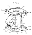
- Fig. 2 shows, in a detached perspective view, the metal casing fixed in pole base.
- Figs. 3, 4 and 5 show, in three views, at the casing, the arrangement connecting the control unit and the feet to the housing.
- FIG. 5 is a top view without the chamber assembly cut-off and insulating column.
- a pole breaker with unipolar control includes a switching chamber 1 linked to an insulating column 2 the lower end of which is fixed to a support 4 which rests on the ground to which it is fixed by flanges 5 at the bottom of the support.
- the support 4 consists of simple feet 4a, 4b, 4c and 4d, completely independent of each other and fixed, each, directly on the casing 3 in the upper part and in the lower part: on the upper flange 10 and the flange lower 11 of the casing by screws 20 in tapped holes 21.
- the pole is operated by a mechanical control unit 6 fixed directly or by means of a adapter parts 7 on the metal casing 3 as shown in FIGS. 3 to 5.
- This adaptation piece 7 can also be an integral part of the control unit 6.
- control unit 6 is thus fixed, directly, by means of the adaptation piece 7 to the metal casing 3 by screws 8 which are fixed in holes threaded 9 of the upper flange 10 and of the lower flange 11 of the metal casing 3.
- the control unit 6 includes at the output a visible control shaft 12 dotted Fig. 4.
- the metal casing 3 comprises at the outlet, by the orifice referenced 13 in FIG. 2 showing the casing 3 in isolation, a rotary shaft 14 of the pole.
- This rotary shaft 14 is visible in dotted lines FIG. 4.
- the control unit 6 is fixed to the metal casing 3 so that that the control shaft 12 and the rotary shaft 14 are coaxial.
- a sleeve coupling 15 connects the two shafts 12 and 14. It is for example a sleeve fluted connecting two fluted trees. We could also have a male tree and another female or other means of mating.
- the insulating column 2 comprises at its lower end a flange 16 for its attachment to the upper flange 10 of the casing metallic 3.
- the assembly constituted by the breaking chamber 1, the insulating column 2, the metal casing 3 and the mechanical control unit 6, is assembled and adjusted in factory.
- the assembly is raised vertically, with a lifting means and it is fixed to the ground by the flanges 5 at the ends of the feet.
- flanges upper 10 and lower 11 could be triangular and we would only have three feet.
- This structure where the support 4 consists only of independent feet, each from the others and fixed directly to the metal casing 3 at a high point and at a low point of the housing ensures both a stiffening of the housing and excellent resistance to feet. Indeed, this fixing of the feet at two points is equivalent to embedding. The mechanical resistance to buckling is excellent.
- control unit 6 The direct attachment of the control unit 6 to the casing 3 also contributes to the mutellle stiffening of the casing and of the control box.
- the structure of the whole is very simple and there is no longer a cover surrounding the casing as in the document earlier cited.
Landscapes
- Driving Mechanisms And Operating Circuits Of Arc-Extinguishing High-Tension Switches (AREA)
- Patch Boards (AREA)
- Train Traffic Observation, Control, And Security (AREA)
- Interface Circuits In Exchanges (AREA)
Abstract
Description
Claims (4)
- Pôle de disjoncteur à commande unipolaire comportant une chambre de coupure (1) liée à une colonne isolante (2) dont l'extrémité inférieure est fixée à un carter métallique (3) d'une face duquel sort un arbre rotatif (14) d'actionnement du pôle, l'ensemble étant fixé à un support et comprenant un boítier de commande mécanique (6) comportant en sortie un arbre de commande (12), caractérisé en ce que ledit support (4) est constitué de pieds (4a à 4d) indépendants les uns des autres et fixés chacun directement sur ledit carter métallique (3) en au moins deux points situés respectivement à la partie supérieure et à la partie inférieure dudit carter.
- Pôle de disjoncteur selon la revendication 1, caractérisé en ce que ledit boítier de commande est fixé audit carter métallique (3), directement ou par l'intermédiaire d'une pièce d'adaptation (7)..
- Procédé de mise en place d'un pôle de disjoncteur selon la revendication 2, caractérisé en ce que l'ensemble formé par la chambre de coupure (1), la colonne isolante (2), le carter métallique (3) et ledit boítier de commande mécanique (6), est assemblé et réglé en usine, puis transporté sur le site, en ce que, sur cet ensemble disposé horizontalement, on monte lesdits pieds (4a à 4d) et en ce que, avec un moyen de levage, on relève l'ensemble à la verticale et l'on bride au sol les pieds (4a à 4d).
- Ensemble comportant une chambre de coupure (1) de pôle de disjoncteur à commande unipolaire, une colonne isolante (2) liée à la chambre de coupure, un carter métallique (3) d'une face duquel sort un arbre rotatif (14) d'actionnement du pôle, fixé à l'extrémité inférieure de la colonne isolante et un boítier de commande mécanique (6) comportant en sortie un arbre de commande (12) caractérisé en ce que ledit boítier de commande est fixé audit carter métallique (3), directement ou par l'intermédiaire d'une pièce d'adaptation (7) et en ce que ledit carter métallique (3) comporte des moyens (21) situés en partie haute (10) et en partie basse (11) du carter (3) pour pouvoir y fixer sur le site des pieds supports.
Applications Claiming Priority (2)
| Application Number | Priority Date | Filing Date | Title |
|---|---|---|---|
| FR9915499 | 1999-12-08 | ||
| FR9915499A FR2802331B1 (fr) | 1999-12-08 | 1999-12-08 | Pole de disjoncteur a commande unipolaire |
Publications (2)
| Publication Number | Publication Date |
|---|---|
| EP1107271A1 true EP1107271A1 (fr) | 2001-06-13 |
| EP1107271B1 EP1107271B1 (fr) | 2006-06-21 |
Family
ID=9553034
Family Applications (1)
| Application Number | Title | Priority Date | Filing Date |
|---|---|---|---|
| EP00403323A Expired - Lifetime EP1107271B1 (fr) | 1999-12-08 | 2000-11-28 | Pôle de disjoncteur à commande unipolaire |
Country Status (4)
| Country | Link |
|---|---|
| EP (1) | EP1107271B1 (fr) |
| AT (1) | ATE331294T1 (fr) |
| DE (1) | DE60028911T2 (fr) |
| FR (1) | FR2802331B1 (fr) |
Cited By (1)
| Publication number | Priority date | Publication date | Assignee | Title |
|---|---|---|---|---|
| CN117174525A (zh) * | 2023-09-21 | 2023-12-05 | 西门子能源高压开关(杭州)有限公司 | 用于罐式断路器的支架组件和该组件的运输和组装方法 |
Citations (3)
| Publication number | Priority date | Publication date | Assignee | Title |
|---|---|---|---|---|
| CH356182A (de) * | 1956-12-14 | 1961-08-15 | Siemens Ag | Hochspannungsschalter |
| DE8705155U1 (de) * | 1987-04-07 | 1988-08-04 | Siemens AG, 1000 Berlin und 8000 München | Hochspannungs-Leistungsschalter, insbesondere Druckgas-Leistungsschalter |
| FR2719153A1 (fr) * | 1994-04-21 | 1995-10-27 | Gec Alsthom T & D Sa | Liaison entre un pôle de disjoncteur et sa commande. |
-
1999
- 1999-12-08 FR FR9915499A patent/FR2802331B1/fr not_active Expired - Fee Related
-
2000
- 2000-11-28 EP EP00403323A patent/EP1107271B1/fr not_active Expired - Lifetime
- 2000-11-28 DE DE60028911T patent/DE60028911T2/de not_active Expired - Lifetime
- 2000-11-28 AT AT00403323T patent/ATE331294T1/de not_active IP Right Cessation
Patent Citations (3)
| Publication number | Priority date | Publication date | Assignee | Title |
|---|---|---|---|---|
| CH356182A (de) * | 1956-12-14 | 1961-08-15 | Siemens Ag | Hochspannungsschalter |
| DE8705155U1 (de) * | 1987-04-07 | 1988-08-04 | Siemens AG, 1000 Berlin und 8000 München | Hochspannungs-Leistungsschalter, insbesondere Druckgas-Leistungsschalter |
| FR2719153A1 (fr) * | 1994-04-21 | 1995-10-27 | Gec Alsthom T & D Sa | Liaison entre un pôle de disjoncteur et sa commande. |
Cited By (2)
| Publication number | Priority date | Publication date | Assignee | Title |
|---|---|---|---|---|
| CN117174525A (zh) * | 2023-09-21 | 2023-12-05 | 西门子能源高压开关(杭州)有限公司 | 用于罐式断路器的支架组件和该组件的运输和组装方法 |
| CN117174525B (zh) * | 2023-09-21 | 2024-04-02 | 西门子能源高压开关(杭州)有限公司 | 用于罐式断路器的支架组件和该组件的运输和组装方法 |
Also Published As
| Publication number | Publication date |
|---|---|
| EP1107271B1 (fr) | 2006-06-21 |
| DE60028911D1 (de) | 2006-08-03 |
| FR2802331B1 (fr) | 2002-02-01 |
| DE60028911T2 (de) | 2007-01-18 |
| ATE331294T1 (de) | 2006-07-15 |
| FR2802331A1 (fr) | 2001-06-15 |
Similar Documents
| Publication | Publication Date | Title |
|---|---|---|
| EP2409553B1 (fr) | Ensemble de commande comportant un variateur de vitesse et un disjoncteur | |
| FR2711019A1 (fr) | Armoire à appareils. | |
| FR2593085A1 (fr) | Table de laboratoire. | |
| FR2632769A1 (fr) | Agencement de verrouillage pour disjoncteur en boitier moule | |
| EP1107271B1 (fr) | Pôle de disjoncteur à commande unipolaire | |
| CA2325723A1 (fr) | Interrupteur de centrale avec echangeur-radiateur | |
| FR2678717A1 (fr) | Radiateur electrique a elements modulaires a accumulation d'energie. | |
| CH350341A (fr) | Cellule préfabriquée destinée à une installation de transport d'énergie | |
| FR2581242A1 (fr) | Dispositif de commande electrique adaptable a un dispositif de commutation a deux etats | |
| EP0058589B1 (fr) | Adaptateur à interrupteur différentiel | |
| FR2501959A1 (fr) | Tondeuse a gazon rotative comportant a l'arriere un montage protege-pieds | |
| EP1403587A1 (fr) | Thermostat de four | |
| FR2695792A1 (fr) | Ensemble pour appareils électroniques de commande et procédé de fabrication pour la mise en Óoeuvre de cet ensemble. | |
| BE1000383A6 (fr) | Appareil de commande et de reglage, en particulier pour installations de chauffage. | |
| FR2517486A1 (fr) | Poste electrique exterieur | |
| EP2162893B1 (fr) | Appareil electrique de coupure comportant une fonction electrique complementaire. | |
| FR2525807A1 (fr) | Disjoncteur avec transformateur de courant incorpore | |
| FR2763234A1 (fr) | Dispositif pour la fabrication de creme fouettee | |
| FR2802333A1 (fr) | Unite formant borne pour un commutateur multipolaire | |
| EP0730329A1 (fr) | Gaine pour la fixation de coffrets électriques et/ou analogues en saillie sur un mur ou bien à l'intérieur d'un mur dans un logement collectif ou individuel,un bâtiment tertiaire ou industriel | |
| FR2597313A3 (fr) | Meuble pour machine a laver du type menager. | |
| BE897895A (fr) | Appareil de commande et de regulation pour installation de chauffage | |
| FR2761139A1 (fr) | Embase de fixation d'un luminaire de rue ou appareil similaire a un mur | |
| FR2778015A3 (fr) | Interrupteur de puissance a basse tension dote d'un boitier comportant une paroi avant et une paroi arriere | |
| KR830001685Y1 (ko) | 전기 스위치 장치 |
Legal Events
| Date | Code | Title | Description |
|---|---|---|---|
| PUAI | Public reference made under article 153(3) epc to a published international application that has entered the european phase |
Free format text: ORIGINAL CODE: 0009012 |
|
| AK | Designated contracting states |
Kind code of ref document: A1 Designated state(s): AT BE CH CY DE DK ES FI FR GB GR IE IT LI LU MC NL PT SE TR |
|
| AX | Request for extension of the european patent |
Free format text: AL;LT;LV;MK;RO;SI |
|
| 17P | Request for examination filed |
Effective date: 20011213 |
|
| AKX | Designation fees paid |
Free format text: AT BE CH CY DE DK ES FI FR GB GR IE IT LI LU MC NL PT SE TR |
|
| RAP1 | Party data changed (applicant data changed or rights of an application transferred) |
Owner name: AREVA T&D SA |
|
| GRAP | Despatch of communication of intention to grant a patent |
Free format text: ORIGINAL CODE: EPIDOSNIGR1 |
|
| GRAS | Grant fee paid |
Free format text: ORIGINAL CODE: EPIDOSNIGR3 |
|
| GRAA | (expected) grant |
Free format text: ORIGINAL CODE: 0009210 |
|
| AK | Designated contracting states |
Kind code of ref document: B1 Designated state(s): AT BE CH CY DE DK ES FI FR GB GR IE IT LI LU MC NL PT SE TR |
|
| PG25 | Lapsed in a contracting state [announced via postgrant information from national office to epo] |
Ref country code: IT Free format text: LAPSE BECAUSE OF FAILURE TO SUBMIT A TRANSLATION OF THE DESCRIPTION OR TO PAY THE FEE WITHIN THE PRE;WARNING: LAPSES OF ITALIAN PATENTS WITH EFFECTIVE DATE BEFORE 2007 MAY HAVE OCCURRED AT ANY TIME BEFORE 2007. THE CORRECT EFFECTIVE DATE MAY BE DIFFERENT FROM THE ONE RECORDED.SCRIBED TIME-LIMIT Effective date: 20060621 Ref country code: IE Free format text: LAPSE BECAUSE OF FAILURE TO SUBMIT A TRANSLATION OF THE DESCRIPTION OR TO PAY THE FEE WITHIN THE PRESCRIBED TIME-LIMIT Effective date: 20060621 Ref country code: NL Free format text: LAPSE BECAUSE OF FAILURE TO SUBMIT A TRANSLATION OF THE DESCRIPTION OR TO PAY THE FEE WITHIN THE PRESCRIBED TIME-LIMIT Effective date: 20060621 Ref country code: FI Free format text: LAPSE BECAUSE OF FAILURE TO SUBMIT A TRANSLATION OF THE DESCRIPTION OR TO PAY THE FEE WITHIN THE PRESCRIBED TIME-LIMIT Effective date: 20060621 |
|
| REG | Reference to a national code |
Ref country code: GB Ref legal event code: FG4D Free format text: NOT ENGLISH |
|
| REG | Reference to a national code |
Ref country code: CH Ref legal event code: EP |
|
| REG | Reference to a national code |
Ref country code: IE Ref legal event code: FG4D Free format text: LANGUAGE OF EP DOCUMENT: FRENCH |
|
| REF | Corresponds to: |
Ref document number: 60028911 Country of ref document: DE Date of ref document: 20060803 Kind code of ref document: P |
|
| PG25 | Lapsed in a contracting state [announced via postgrant information from national office to epo] |
Ref country code: DK Free format text: LAPSE BECAUSE OF FAILURE TO SUBMIT A TRANSLATION OF THE DESCRIPTION OR TO PAY THE FEE WITHIN THE PRESCRIBED TIME-LIMIT Effective date: 20060921 |
|
| PG25 | Lapsed in a contracting state [announced via postgrant information from national office to epo] |
Ref country code: ES Free format text: LAPSE BECAUSE OF FAILURE TO SUBMIT A TRANSLATION OF THE DESCRIPTION OR TO PAY THE FEE WITHIN THE PRESCRIBED TIME-LIMIT Effective date: 20061002 |
|
| REG | Reference to a national code |
Ref country code: SE Ref legal event code: TRGR |
|
| GBT | Gb: translation of ep patent filed (gb section 77(6)(a)/1977) |
Effective date: 20060924 |
|
| PGFP | Annual fee paid to national office [announced via postgrant information from national office to epo] |
Ref country code: AT Payment date: 20061113 Year of fee payment: 7 |
|
| PG25 | Lapsed in a contracting state [announced via postgrant information from national office to epo] |
Ref country code: PT Free format text: LAPSE BECAUSE OF FAILURE TO SUBMIT A TRANSLATION OF THE DESCRIPTION OR TO PAY THE FEE WITHIN THE PRESCRIBED TIME-LIMIT Effective date: 20061121 |
|
| PGFP | Annual fee paid to national office [announced via postgrant information from national office to epo] |
Ref country code: GB Payment date: 20061122 Year of fee payment: 7 |
|
| PG25 | Lapsed in a contracting state [announced via postgrant information from national office to epo] |
Ref country code: BE Free format text: LAPSE BECAUSE OF NON-PAYMENT OF DUE FEES Effective date: 20061130 Ref country code: MC Free format text: LAPSE BECAUSE OF NON-PAYMENT OF DUE FEES Effective date: 20061130 |
|
| NLV1 | Nl: lapsed or annulled due to failure to fulfill the requirements of art. 29p and 29m of the patents act | ||
| REG | Reference to a national code |
Ref country code: IE Ref legal event code: FD4D |
|
| PLBE | No opposition filed within time limit |
Free format text: ORIGINAL CODE: 0009261 |
|
| STAA | Information on the status of an ep patent application or granted ep patent |
Free format text: STATUS: NO OPPOSITION FILED WITHIN TIME LIMIT |
|
| 26N | No opposition filed |
Effective date: 20070322 |
|
| BERE | Be: lapsed |
Owner name: AREVA T&D SA Effective date: 20061130 |
|
| PG25 | Lapsed in a contracting state [announced via postgrant information from national office to epo] |
Ref country code: GR Free format text: LAPSE BECAUSE OF FAILURE TO SUBMIT A TRANSLATION OF THE DESCRIPTION OR TO PAY THE FEE WITHIN THE PRESCRIBED TIME-LIMIT Effective date: 20060922 |
|
| GBPC | Gb: european patent ceased through non-payment of renewal fee |
Effective date: 20071128 |
|
| PG25 | Lapsed in a contracting state [announced via postgrant information from national office to epo] |
Ref country code: LU Free format text: LAPSE BECAUSE OF NON-PAYMENT OF DUE FEES Effective date: 20061128 Ref country code: TR Free format text: LAPSE BECAUSE OF FAILURE TO SUBMIT A TRANSLATION OF THE DESCRIPTION OR TO PAY THE FEE WITHIN THE PRESCRIBED TIME-LIMIT Effective date: 20060621 |
|
| PG25 | Lapsed in a contracting state [announced via postgrant information from national office to epo] |
Ref country code: AT Free format text: LAPSE BECAUSE OF NON-PAYMENT OF DUE FEES Effective date: 20071128 |
|
| PG25 | Lapsed in a contracting state [announced via postgrant information from national office to epo] |
Ref country code: CY Free format text: LAPSE BECAUSE OF FAILURE TO SUBMIT A TRANSLATION OF THE DESCRIPTION OR TO PAY THE FEE WITHIN THE PRESCRIBED TIME-LIMIT Effective date: 20060621 |
|
| PG25 | Lapsed in a contracting state [announced via postgrant information from national office to epo] |
Ref country code: GB Free format text: LAPSE BECAUSE OF NON-PAYMENT OF DUE FEES Effective date: 20071128 |
|
| REG | Reference to a national code |
Ref country code: DE Ref legal event code: R082 Ref document number: 60028911 Country of ref document: DE Representative=s name: ZEITLER VOLPERT KANDLBINDER, DE |
|
| REG | Reference to a national code |
Ref country code: FR Ref legal event code: CA Effective date: 20121204 Ref country code: FR Ref legal event code: CD Owner name: ALSTOM GRID SAS, FR Effective date: 20121204 |
|
| REG | Reference to a national code |
Ref country code: DE Ref legal event code: R082 Ref document number: 60028911 Country of ref document: DE Representative=s name: ZEITLER VOLPERT KANDLBINDER, DE Effective date: 20121211 Ref country code: DE Ref legal event code: R081 Ref document number: 60028911 Country of ref document: DE Owner name: ALSTOM TECHNOLOGY LTD., CH Free format text: FORMER OWNER: AREVA T&D S.A., LEVALLOIS-PERRET, FR Effective date: 20121211 Ref country code: DE Ref legal event code: R081 Ref document number: 60028911 Country of ref document: DE Owner name: ALSTOM GRID SAS, FR Free format text: FORMER OWNER: AREVA T&D S.A., LEVALLOIS-PERRET, FR Effective date: 20121211 Ref country code: DE Ref legal event code: R082 Ref document number: 60028911 Country of ref document: DE Representative=s name: ZEITLER VOLPERT KANDLBINDER PATENTANWAELTE PAR, DE Effective date: 20121211 Ref country code: DE Ref legal event code: R082 Ref document number: 60028911 Country of ref document: DE Representative=s name: ZEITLER VOLPERT KANDLBINDER PATENT- UND RECHTS, DE Effective date: 20121211 |
|
| REG | Reference to a national code |
Ref country code: DE Ref legal event code: R082 Ref document number: 60028911 Country of ref document: DE Representative=s name: ZEITLER VOLPERT KANDLBINDER, DE |
|
| REG | Reference to a national code |
Ref country code: DE Ref legal event code: R082 Ref document number: 60028911 Country of ref document: DE Representative=s name: ZEITLER VOLPERT KANDLBINDER, DE Effective date: 20130610 Ref country code: DE Ref legal event code: R081 Ref document number: 60028911 Country of ref document: DE Owner name: ALSTOM TECHNOLOGY LTD., CH Free format text: FORMER OWNER: ALSTOM GRID SAS, PARIS, FR Effective date: 20130610 Ref country code: DE Ref legal event code: R082 Ref document number: 60028911 Country of ref document: DE Representative=s name: ZEITLER VOLPERT KANDLBINDER PATENTANWAELTE PAR, DE Effective date: 20130610 Ref country code: DE Ref legal event code: R082 Ref document number: 60028911 Country of ref document: DE Representative=s name: ZEITLER VOLPERT KANDLBINDER PATENT- UND RECHTS, DE Effective date: 20130610 |
|
| REG | Reference to a national code |
Ref country code: FR Ref legal event code: TP Owner name: ALSTOM TECHNOLOGY LTD, CH Effective date: 20130710 |
|
| REG | Reference to a national code |
Ref country code: CH Ref legal event code: PUE Owner name: ALSTOM TECHNOLOGY LTD, CH Free format text: FORMER OWNER: AREVA T&D SA, FR |
|
| REG | Reference to a national code |
Ref country code: FR Ref legal event code: PLFP Year of fee payment: 16 |
|
| REG | Reference to a national code |
Ref country code: FR Ref legal event code: PLFP Year of fee payment: 17 |
|
| REG | Reference to a national code |
Ref country code: FR Ref legal event code: PLFP Year of fee payment: 18 |
|
| REG | Reference to a national code |
Ref country code: FR Ref legal event code: PLFP Year of fee payment: 19 |
|
| PGFP | Annual fee paid to national office [announced via postgrant information from national office to epo] |
Ref country code: SE Payment date: 20191025 Year of fee payment: 20 Ref country code: DE Payment date: 20191021 Year of fee payment: 20 |
|
| PGFP | Annual fee paid to national office [announced via postgrant information from national office to epo] |
Ref country code: IT Payment date: 20191021 Year of fee payment: 20 Ref country code: FR Payment date: 20191022 Year of fee payment: 20 |
|
| PGFP | Annual fee paid to national office [announced via postgrant information from national office to epo] |
Ref country code: CH Payment date: 20191022 Year of fee payment: 20 |
|
| REG | Reference to a national code |
Ref country code: DE Ref legal event code: R071 Ref document number: 60028911 Country of ref document: DE |
|
| REG | Reference to a national code |
Ref country code: CH Ref legal event code: PL |