EP1107232A2 - Joint stereo coding of audio signals - Google Patents
Joint stereo coding of audio signals Download PDFInfo
- Publication number
- EP1107232A2 EP1107232A2 EP00310510A EP00310510A EP1107232A2 EP 1107232 A2 EP1107232 A2 EP 1107232A2 EP 00310510 A EP00310510 A EP 00310510A EP 00310510 A EP00310510 A EP 00310510A EP 1107232 A2 EP1107232 A2 EP 1107232A2
- Authority
- EP
- European Patent Office
- Prior art keywords
- signal
- component
- representation
- information
- coefficients
- Prior art date
- Legal status (The legal status is an assumption and is not a legal conclusion. Google has not performed a legal analysis and makes no representation as to the accuracy of the status listed.)
- Granted
Links
Images
Classifications
-
- H—ELECTRICITY
- H04—ELECTRIC COMMUNICATION TECHNIQUE
- H04S—STEREOPHONIC SYSTEMS
- H04S1/00—Two-channel systems
- H04S1/007—Two-channel systems in which the audio signals are in digital form
-
- G—PHYSICS
- G10—MUSICAL INSTRUMENTS; ACOUSTICS
- G10L—SPEECH ANALYSIS TECHNIQUES OR SPEECH SYNTHESIS; SPEECH RECOGNITION; SPEECH OR VOICE PROCESSING TECHNIQUES; SPEECH OR AUDIO CODING OR DECODING
- G10L19/00—Speech or audio signals analysis-synthesis techniques for redundancy reduction, e.g. in vocoders; Coding or decoding of speech or audio signals, using source filter models or psychoacoustic analysis
- G10L19/008—Multichannel audio signal coding or decoding using interchannel correlation to reduce redundancy, e.g. joint-stereo, intensity-coding or matrixing
-
- G—PHYSICS
- G10—MUSICAL INSTRUMENTS; ACOUSTICS
- G10L—SPEECH ANALYSIS TECHNIQUES OR SPEECH SYNTHESIS; SPEECH RECOGNITION; SPEECH OR VOICE PROCESSING TECHNIQUES; SPEECH OR AUDIO CODING OR DECODING
- G10L19/00—Speech or audio signals analysis-synthesis techniques for redundancy reduction, e.g. in vocoders; Coding or decoding of speech or audio signals, using source filter models or psychoacoustic analysis
- G10L19/02—Speech or audio signals analysis-synthesis techniques for redundancy reduction, e.g. in vocoders; Coding or decoding of speech or audio signals, using source filter models or psychoacoustic analysis using spectral analysis, e.g. transform vocoders or subband vocoders
-
- H—ELECTRICITY
- H04—ELECTRIC COMMUNICATION TECHNIQUE
- H04S—STEREOPHONIC SYSTEMS
- H04S2420/00—Techniques used stereophonic systems covered by H04S but not provided for in its groups
- H04S2420/03—Application of parametric coding in stereophonic audio systems
Definitions
- the invention relates to systems and methods for communications of a signal containing information, and more particularly to systems and methods for coding a signal containing, e.g., stereo audio information, to efficiently utilize limited transmission bandwidth.
- each block is divided into coder bands, each of which is individually coded, based on psycho-acoustic criteria, in such a way that the audio information is significantly compressed, thereby requiring a smaller number of bits to represent the audio information than would be the case if the audio information were represented in a more simplistic digital format, such as the PCM format.
- a stereo audio signal including a left channel signal (L) and a right channel signal (R) may be further encoded to realize additional savings in transmission bandwidth.
- M (L + R)/2
- S (L - R)/2.
- M provides a monophonic effect of the stereo signal while S adds thereto a stereo separation based on the difference between L and R.
- L and R the more bits are required to represent S.
- an M-S encoded stereo audio signal is undesirably susceptible to aliasing distortion attributed to the limited transmission bandwidth.
- mode distortion is introduced to the received signal, thereby significantly degrading its stereo quality.
- intensity stereo coding Another prior art technique for further encoding a stereo audio signal to save transmission bandwidth is known as the intensity stereo coding.
- the intensity stereo coding was developed based on the recognition that the ability of a human auditory system to resolve the exact locations of audio sources of L and R decreases towards high frequencies. Typically, it is used to encode the intensity or magnitude of high frequency components of only one of L and R. However, the resulting encoded information facilitates recovery of the high frequency components of both L and R.
- the representation of a composite signal for transmission, which includes a first signal and a second signal (e.g., L and R), contains first information derived from at least the first signal, and second information concerning one or more coefficients resulting from parametric coding of the second signal.
- the first signal may be recovered based on the first information
- the second signal may be recovered based on the first information and the second information.
- the transmission bandwidth is efficiently utilized for communicating the composite signal.
- such coefficients describe not only an intensity relation between the first signal and the second signal, but also phase relations therebetween.
- the signal quality afforded by the inventive parametric coding is superior to that afforded, e.g., by the intensity stereo coding described above.
- Fig. 1 illustrates arrangement 100 embodying the principles of the invention for communicating information, e.g., stereo audio information.
- server 105 in arrangement 100 provides a music-on-demand service to client terminals through Internet 120.
- client terminals is numerically denoted 130 which may be a personal computer (PC).
- Internet 120 is a packet switched network for transporting information in packets in accordance with the standard transmission control protocol/Internet protocol (TCP/IP).
- TCP/IP transmission control protocol/Internet protocol
- client terminal 130 for communicating information with server 105, which is identified by a predetermined uniform resource locator (URL) on Internet 120.
- server 105 For example, to request the music-on-demand service provided by server 105, a modem (not shown) in client terminal 130 is used to establish communication connection 125 with Internet 120.
- connection 125 affords a 28.8 kb/sec communication rate, which is common.
- client terminal 130 is assigned an IP address for its identification.
- the user at client terminal 130 may then access the music-on-demand service at the predetermined URL identifying server 105, and request a selected musical piece from the service.
- a request includes the IP address identifying client terminal 130, and information concerning the selected musical piece and communication rate of terminal 130, i.e., 28.8 kb/s in this instance, which affords narrow bandwidth for communication of the musical piece.
- a stereo audio signal can be characterized using localization cues, which define the location or tilt of the underlying stereo sounds in an auditory space. Of course, some sounds may not be localized, which are perceived as diffuse across a left-to-right span.
- the localization cues include (a) low frequency phase cues, (b) intensity cues, and (c) group delay or envelope cues.
- the low frequency phase cues may be derived from the relative phase of L and R at low frequencies of the signals. Specifically, the phase relationship between their frequency components below 1200 Hz was found to be of particular importance.
- the intensity cues may be derived from the relative power of L and R at high frequencies of the signals, e.g., above 1200 Hz.
- the envelope cues may be derived from the relative phase of L and R signal envelopes, and may be determined based on the group delay between the two signals. It should be noted that cues (b) and (c) may be collectively referred to as the "phase cues.”
- a representation of the stereo audio signal contains (i) information concerning only one of L and R, e.g., L here, and (ii) parametric information concerning the other signal, e.g., R, resulting from parametric coding of R with respect to L.
- Such a stereo audio signal representation is hereinafter referred to as the "ST representation.”
- parametric information concerning R is hereinafter referred to as "param-R.”
- param-R is obtained by quantizing a set of parameters describing the aforementioned localization cues of the stereo audio signal.
- the stereo audio signal recovered based on the ST representation includes L and a prediction of R, affording an acceptable stereo audio quality, where L is derived from the L information in the ST representation, and the prediction of R is derived from both the param-R and L information therein.
- R f ⁇ L f , where R f represents the frequency spectrum of R, L f represents the frequency spectrum of L, and a represents a predictor coefficient from which param-R is derived.
- R i f ⁇ i L i f , where i represents an index for an i th prediction frequency band in the frequency range.
- each i th prediction frequency band may coincide with a different one of the coder bands which approximate the well known critical bands of the human auditory system, in accordance with the PAC technique.
- PAC perceptual audio coding
- L i f real-causal (or R i f real-causal ) is realized by appending "zeros" to a block of N samples representing L to lengthen the block to (2N-1) samples long, followed by a frequency transform of the zero-padded block and extraction of the real part of the resulting transform, where N is a predetermined number.
- a multi-tap predictor may be utilized whereby ⁇ i represents a set of predictor coefficients for an i th prediction frequency band.
- the predictor coefficients ⁇ i 0 and ⁇ i 1 may be determined by solving the following equation: where the superscript "T” denotes a standard matrix transposition operation. Thus, where and the superscript "-1" denotes a standard matrix inverse operation.
- param-R in the ST representation comprises information concerning predictor coefficients ⁇ i 0 and ⁇ i 1 describing the localization cues, i.e., the low frequency phase cues, intensity cues and envelope cues, of the underlying stereo audio signal.
- param-R together with the L information in the ST representation is used for predicting R.
- the communication rate 28.8 kb/sec affordable by connection 125 in this instance, about 22 kb/sec may be allocated to the transmission of the L information and about 2 kb/sec to the transmission of param-R.
- Equation (6) it can be shown that if L is weak, and thus det G (i.e, determinant of G) has a small value, equation (6) for solving ⁇ i 0 and ⁇ i 1 would be numerically ill conditioned. As a consequence, use of the resulting ⁇ i 0 and ⁇ i 1 , and thus param-R, to predict R based on L is not viable.
- the disclosure hereupon is based on the generalized, second parametric coding technique involving L*.
- the generalized parametric coding technique may be more advantageous to employ the generalized parametric coding technique especially when the stereo audio signal to be coded includes an extremely strong stereo tilt (i.e., almost completely dominated by either L or R).
- the pair L* and R in accordance with the generalized technique exhibits a reduced stereo separation, thereby increasing the "naturalness" of the parametric coding.
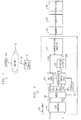
- Fig. 2 illustrates server 105 wherein audio coder 203 is used to process a stereo audio signal representing a musical piece, which consists of L and R.
- analog-to-digital (A/D) convertor 205 in coder 203 digitizes L and R, thereby providing PCM samples of L and R denoted L(n) and R(n), respectively, where n represents an index for an n th sample interval.
- mixer 207 Based on L(n) and R(n), mixer 207 generates L*(n) on lead 209a in accordance with expression (7) above, where values of a and b are adaptively selected by adapter 211 described below.
- R(n) and L(n) bypass mixer 207 onto leads 209b and 209c, respectively. Leads 209a-209c extend, and thereby provide the respective L*(n), R(n) and L(n), to parametric stereo coder 215 described below.
- L*(n) is also provided to PAC coder 217.
- PAC coder 217 divides the PCM samples L*(n) into time domain blocks, and performs a modified discrete cosine transform (MDCT) on each block to provide a frequency domain representation therefor.
- MDCT modified discrete cosine transform
- the resulting MDCT coefficients are grouped according to coder bands for quantization. As mentioned before, these coder bands approximate the well known critical bands of the human auditory system.
- PAC coder 217 also analyzes the audio signal samples, L*(n), to determine the appropriate level of quantization (i.e., quantization stepsize) for each coder band. This level of quantization is determined based on an assessment of how well the audio signal in a given coder band masks noise.
- the quantized MDCT coefficients then undergo a conventional Huffman compression process, resulting in a bit stream representing L* on lead 222a.
- parametric stereo coder 215 Based on received L*(n) and R(n), parametric stereo coder 215 generates a parametric signal P* R .
- P* R contains information concerning param-R[w.r.t. L*] which comprises predictor coefficients á i 0 and á i 1 in accordance with equation (6) above, although "1" and "1'" therein are derived from L* here, rather than L, pursuant to the generalized parametric coding technique.
- P* R is quantized by conventional nonlinear quantizer 225, thereby providing a bit stream representing P* R on lead 222b.
- Leads 222a and 222b extend to ST representation formatter 231 where for each time domain block, the bit stream representing P* R on lead 222b corresponding to the time domain block is appended to that representing L* on lead 222a corresponding to the same time domain block, resulting in the ST representation of the musical piece being processed.
- the latter is stored in memory 270, along with the ST representations of other musical pieces processed in a similar manner.
- represent the magnitudes of l (f) and (f), respectively.
- a + b 1 as mentioned before, the value selected by adapter 211 for b simply equals 1 - a. It should be noted that alternatively, a and b may be predetermined constant values, thereby obviating the need of adapter 211.
- processor 280 In response to the aforementioned request from client terminal 130 for transmission of the selected musical piece thereto, processor 280 causes packetizer 285 to retrieve from memory 270 the ST representation of the selected musical piece and generate a sequence of packets in accordance with the standard TCP/IP. These packets have information fields jointly containing the ST representation of the selected musical piece. Each packet in the sequence is destined for client terminal 130 as it contains in its header, as a destination address, the IP address of terminal 130 requesting the music-on-demand service.
- Fig. 3 illustrates one such packet sequence.
- the header of each packet contains synchronization information.
- the synchronization information in each packet includes a sequence index indicating a time segment i, 1 ⁇ i ⁇ N, to which the packet corresponds, where N is the total number of time segments which the selected musical piece comprises.
- each time segment has the same predetermined length.
- field 301 in the header of packet 310 contains a sequence index "1" indicating that packet 310 corresponds to the first time segment;
- field 303 in the header of packet 320 contains a sequence index "2" indicating that packet 320 corresponds to the second time segment;
- field 305 in the header of packet 430 contains a sequence index "3" indicating that packet 330 corresponds to the third time segment; and so on and so forth.
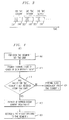
- Client terminal 130 processes the packet sequence from server 105 on a time segment by time segment basis, in accordance with a routine which may be realized using software and/or hardware installed in terminal 130.
- Fig. 4 illustrates such a routine denoted 400.
- terminal 130 sets a predetermined time limit within which any packet corresponding to the time segment is received for processing.
- Terminal 130 at step 411 examines the aforementioned sequence index in the header of each received packet. Based on the sequence index values of the received packets, terminal 130 at step 414 determines whether the packet for time segment i has been received before the time limit expires. If the expected packet has been received, routine 400 proceeds to step 417 where terminal 130 extracts the ST representation content from the packet.
- terminal 130 performs on the extracted content the inverse function to audio coder 203 described above to recover the L and R corresponding to time segment i.
- terminal 130 performs well known error concealment for time segment i, e.g., interpolation based on the results of audio recovery in neighboring time segments, as indicated at step 424.
- an alternative scheme may be applied to capture the localization cues of a stereo audio signal and effectively represent the signal.
- This alternative scheme is also based on a prediction in the frequency domain, but works with "real" MDCT representations of the signal, as opposed to the complex DFT representations thereof as before.
- the MDCT may be viewed as a block transform with a 50% overlap between two consecutive analysis blocks. That is, for a transform block length B, there is a B/2 overlap between the two consecutive blocks. Furthermore, the transform produces B/2 real transform (frequency) outputs.
- H. Malavar "Lapped Orthogonal Transforms," Prentice Hall, Englewood Cliffs, New Jersey.
- the alternative scheme stems from my recognition that the phase cue information of each frequency content, which is not apparent in the real representation, is embedded in the evolution of MDCT coefficients, i.e., the inter-block correlation of a frequency bin in the MDCT representation.
- the alternative scheme in which the prediction of, say, a right MDCT coefficient is based on left MDCT coefficients in the same frequency bin for the current as well as previous transform block captures intensity and phase cues for stationary signals.
- the alternative scheme can be effectively integrated into a PAC codec with a low computational overhead because the required MDCT representation is made available in the codec anyway, and the alternative scheme performs well especially when the stereo audio signal to be coded is relatively stationary.
- the parametric coding schemes disclosed above are illustratively predicated upon a prediction of R based on L.
- the parametric coding schemes may be predicated upon a prediction of L based on R. In that case, the above discussion still follows, with R and L interchanged.
- the parametric coding technique is illustratively applied to a packet switched communications system.
- inventive technique is equally applicable to broadcasting systems including hybrid in-band on channel (IBOC) AM systems, hybrid IBOC FM systems, satellite broadcasting systems, Internet radio systems, TV broadcasting systems, etc.
- IBOC in-band on channel
- server 105 is disclosed herein in a form in which various server functions are performed by discrete functional blocks. However, any one or more of these functions could equally well be embodied in an arrangement in which the functions of any one or more of those blocks or indeed, all of the functions thereof, are realized, for example, by one or more appropriately programmed processors.
Landscapes
- Engineering & Computer Science (AREA)
- Physics & Mathematics (AREA)
- Acoustics & Sound (AREA)
- Multimedia (AREA)
- Signal Processing (AREA)
- Computational Linguistics (AREA)
- Audiology, Speech & Language Pathology (AREA)
- Human Computer Interaction (AREA)
- Health & Medical Sciences (AREA)
- Spectroscopy & Molecular Physics (AREA)
- Mathematical Physics (AREA)
- Compression, Expansion, Code Conversion, And Decoders (AREA)
- Stereophonic System (AREA)
Abstract
Description


Claims (27)
- A method for processing a signal which includes a first component and a second component thereof, the method comprising:deriving one or more coefficients describing at least a phase relation between the first component and the second component; andgenerating a representation of the signal, the representation containing first information derived from at least the first component, and second information concerning at least the one or more coefficients, a value of the second component being predictable based on the first information and the second information.
- The method of claim 1 wherein the signal includes a stereo audio signal.
- The method of claim 2 wherein the first component includes a left channel signal of the stereo audio signal, and the second component includes a right channel signal thereof.
- The method of claim 1 wherein the phase relation concerns a phase of at least part of the first component relative to a phase of at least part of the second component.
- The method of claim 1 wherein the one or more coefficients also describe an intensity of at least part of the first component relative to an intensity of at least part of the second component.
- The method of claim 1 wherein the one or more coefficients are derived by subjecting the first component and the second component to causality constraints.
- The method of claim 1 wherein the first information is derived from a combination of the first component and the second component.
- The method of claim 7 wherein the combination of the first component and the second component is adaptively determined.
- A method for processing a composite signal which includes a first signal and a second signal, the method comprising:generating a mixed signal based on the first signal and the second signal;coding the mixed signal to generate a representation of the mixed signal;in response to the mixed signal and the first signal, providing information concerning one or more coefficients for predicting the first signal; andgenerating a representation of the composite signal, the representation of the composite signal includes the representation of the mixed signal and the information concerning the one or more coefficients.
- The method of claim 9 wherein the mixed signal is generated in an adaptive manner.
- The method of claim 9 wherein the composite signal includes a stereo audio signal.
- The method of claim 10 wherein the mixed signal is coded in accordance with a PAC technique.
- The method of claim 10 wherein the first signal includes a left channel signal of the stereo audio signal, and the second signal includes a right channel signal thereof.
- The method of claim 10 further comprising packaging the representation of the composite signal in a sequence of packets, each packet including an indicator indicating a sequence order of the packet with respect to other packets.
- A method for recovering a signal which includes a first component and a second component thereof, the method comprising:receiving a representation of the signal, the representation including first information derived from at least the first component, and second information concerning one or more coefficients, which describe at least a phase relation between the first component and the second component;recovering the signal based on the representation; andpredicting a value of the second component based on the first information and the second information in the representation in recovering the signal.
- The method of claim 15 wherein the representation is packaged in a sequence of packets.
- The method of claim 16 wherein the signal is recovered on a time-segment basis, each time segment being associated with a different packet in the sequence.
- The method of claim 17 wherein each packet includes an indicator identifying the time segment with which the packet is associated.
- The method of claim 18 further comprising performing concealment for a time segment in recovering the signal when the packet associated with the time segment is not received within a predetermined period.
- The method of claim 15 wherein the signal includes a stereo audio signal.
- The method of claim 16; wherein the first component includes a left channel signal of the stereo audio signal, and the second component includes a right channel signal thereof.
- The method of claim 15 wherein the phase relation concerns a phase of at least part of the first component relative to a phase of at least part of the second component.
- The method of claim 15 wherein the one or more coefficients also describe an intensity of at least part of the first component relative to an intensity of at least part of the second component.
- The method of claim 15 wherein the one or more coefficients are derived by subjecting the first component and the second component to causality constraints.
- The method of claim 15 wherein the first information is derived from a combination of the first component and the second component.
- The method of claim 25 wherein the combination of the first component and the second component is adaptively determined.
- Apparatus comprising means for carrying out the steps of a method as claimed in any of the preceding claims.
Applications Claiming Priority (2)
| Application Number | Priority Date | Filing Date | Title |
|---|---|---|---|
| US454026 | 1999-12-03 | ||
| US09/454,026 US6539357B1 (en) | 1999-04-29 | 1999-12-03 | Technique for parametric coding of a signal containing information |
Publications (3)
| Publication Number | Publication Date |
|---|---|
| EP1107232A2 true EP1107232A2 (en) | 2001-06-13 |
| EP1107232A3 EP1107232A3 (en) | 2002-10-16 |
| EP1107232B1 EP1107232B1 (en) | 2008-06-25 |
Family
ID=23802983
Family Applications (1)
| Application Number | Title | Priority Date | Filing Date |
|---|---|---|---|
| EP00310510A Expired - Lifetime EP1107232B1 (en) | 1999-12-03 | 2000-11-27 | Joint stereo coding of audio signals |
Country Status (5)
| Country | Link |
|---|---|
| US (1) | US6539357B1 (en) |
| EP (1) | EP1107232B1 (en) |
| JP (2) | JP2001209399A (en) |
| CA (1) | CA2326495C (en) |
| DE (1) | DE60039278D1 (en) |
Cited By (42)
| Publication number | Priority date | Publication date | Assignee | Title |
|---|---|---|---|---|
| WO2003090207A1 (en) * | 2002-04-22 | 2003-10-30 | Koninklijke Philips Electronics N.V. | Parametric multi-channel audio representation |
| WO2004008805A1 (en) * | 2002-07-12 | 2004-01-22 | Koninklijke Philips Electronics N.V. | Audio coding |
| WO2004072956A1 (en) * | 2003-02-11 | 2004-08-26 | Koninklijke Philips Electronics N.V. | Audio coding |
| WO2004086817A3 (en) * | 2003-03-24 | 2005-02-10 | Koninkl Philips Electronics Nv | Coding of main and side signal representing a multichannel signal |
| EP1523863A1 (en) * | 2002-07-16 | 2005-04-20 | Koninklijke Philips Electronics N.V. | Audio coding |
| WO2005098824A1 (en) * | 2004-04-05 | 2005-10-20 | Koninklijke Philips Electronics N.V. | Multi-channel encoder |
| WO2005006566A3 (en) * | 2003-06-27 | 2006-05-18 | Mattel Inc | Adaptive audio communication code |
| CN1307612C (en) * | 2002-04-22 | 2007-03-28 | 皇家飞利浦电子股份有限公司 | Parametric representation of spatial audio |
| US7343281B2 (en) | 2003-03-17 | 2008-03-11 | Koninklijke Philips Electronics N.V. | Processing of multi-channel signals |
| US7382886B2 (en) | 2001-07-10 | 2008-06-03 | Coding Technologies Ab | Efficient and scalable parametric stereo coding for low bitrate audio coding applications |
| EP1944758A2 (en) * | 2004-04-05 | 2008-07-16 | Koninklijke Philips Electronics N.V. | Method of coding data |
| EP1776832A4 (en) * | 2004-08-09 | 2009-08-26 | Korea Electronics Telecomm | THREE-DIMENSIONAL DIGITAL MULTIMEDIA BROADCAST SYSTEM |
| EP1318502A3 (en) * | 2001-11-08 | 2009-10-07 | Grundig Multimedia B.V. | Method for coding audio |
| RU2376655C2 (en) * | 2005-04-19 | 2009-12-20 | Коудинг Текнолоджиз Аб | Energy-dependant quantisation for efficient coding spatial parametres of sound |
| US7644003B2 (en) | 2001-05-04 | 2010-01-05 | Agere Systems Inc. | Cue-based audio coding/decoding |
| US7644001B2 (en) | 2002-11-28 | 2010-01-05 | Koninklijke Philips Electronics N.V. | Differentially coding an audio signal |
| RU2384014C2 (en) * | 2004-10-20 | 2010-03-10 | Фраунхофер-Гезелльшафт Цур Фердерунг Дер Ангевандтен Форшунг Е.Ф. | Generation of scattered sound for binaural coding circuits using key information |
| US7720230B2 (en) | 2004-10-20 | 2010-05-18 | Agere Systems, Inc. | Individual channel shaping for BCC schemes and the like |
| RU2390857C2 (en) * | 2004-04-05 | 2010-05-27 | Конинклейке Филипс Электроникс Н.В. | Multichannel coder |
| US7761304B2 (en) | 2004-11-30 | 2010-07-20 | Agere Systems Inc. | Synchronizing parametric coding of spatial audio with externally provided downmix |
| US7787631B2 (en) | 2004-11-30 | 2010-08-31 | Agere Systems Inc. | Parametric coding of spatial audio with cues based on transmitted channels |
| US7805313B2 (en) | 2004-03-04 | 2010-09-28 | Agere Systems Inc. | Frequency-based coding of channels in parametric multi-channel coding systems |
| RU2407068C2 (en) * | 2004-11-04 | 2010-12-20 | Конинклейке Филипс Электроникс Н.В. | Multichannel coding and decoding |
| CN101071570B (en) * | 2007-06-21 | 2011-02-16 | 北京中星微电子有限公司 | Coupling track coding-decoding processing method, audio coding device and decoding device |
| US7903824B2 (en) | 2005-01-10 | 2011-03-08 | Agere Systems Inc. | Compact side information for parametric coding of spatial audio |
| RU2417549C2 (en) * | 2006-12-07 | 2011-04-27 | ЭлДжи ЭЛЕКТРОНИКС ИНК. | Audio signal processing method and device |
| RU2418385C2 (en) * | 2005-07-14 | 2011-05-10 | Конинклейке Филипс Электроникс Н.В. | Coding and decoding of sound |
| RU2419249C2 (en) * | 2005-09-13 | 2011-05-20 | Кониклейке Филипс Электроникс Н.В. | Audio coding |
| US7961890B2 (en) | 2005-04-15 | 2011-06-14 | Fraunhofer-Gesellschaft Zur Foerderung Der Angewandten Forschung, E.V. | Multi-channel hierarchical audio coding with compact side information |
| US7986788B2 (en) | 2006-12-07 | 2011-07-26 | Lg Electronics Inc. | Method and an apparatus for decoding an audio signal |
| US7991610B2 (en) | 2005-04-13 | 2011-08-02 | Fraunhofer-Gesellschaft Zur Foerderung Der Angewandten Forschung E.V. | Adaptive grouping of parameters for enhanced coding efficiency |
| US8078475B2 (en) * | 2004-05-19 | 2011-12-13 | Panasonic Corporation | Audio signal encoder and audio signal decoder |
| US8184817B2 (en) | 2005-09-01 | 2012-05-22 | Panasonic Corporation | Multi-channel acoustic signal processing device |
| US8265941B2 (en) | 2006-12-07 | 2012-09-11 | Lg Electronics Inc. | Method and an apparatus for decoding an audio signal |
| US8340306B2 (en) | 2004-11-30 | 2012-12-25 | Agere Systems Llc | Parametric coding of spatial audio with object-based side information |
| US8605911B2 (en) | 2001-07-10 | 2013-12-10 | Dolby International Ab | Efficient and scalable parametric stereo coding for low bitrate audio coding applications |
| US8626503B2 (en) | 2005-07-14 | 2014-01-07 | Erik Gosuinus Petrus Schuijers | Audio encoding and decoding |
| US9082395B2 (en) | 2009-03-17 | 2015-07-14 | Dolby International Ab | Advanced stereo coding based on a combination of adaptively selectable left/right or mid/side stereo coding and of parametric stereo coding |
| US9431020B2 (en) | 2001-11-29 | 2016-08-30 | Dolby International Ab | Methods for improving high frequency reconstruction |
| US9542950B2 (en) | 2002-09-18 | 2017-01-10 | Dolby International Ab | Method for reduction of aliasing introduced by spectral envelope adjustment in real-valued filterbanks |
| US10276174B2 (en) | 2010-04-09 | 2019-04-30 | Dolby International Ab | MDCT-based complex prediction stereo coding |
| US11763825B2 (en) | 2017-05-16 | 2023-09-19 | Huawei Technologies Co., Ltd. | Stereo signal processing method and apparatus |
Families Citing this family (34)
| Publication number | Priority date | Publication date | Assignee | Title |
|---|---|---|---|---|
| US6961432B1 (en) * | 1999-04-29 | 2005-11-01 | Agere Systems Inc. | Multidescriptive coding technique for multistream communication of signals |
| JP3507743B2 (en) * | 1999-12-22 | 2004-03-15 | インターナショナル・ビジネス・マシーンズ・コーポレーション | Digital watermarking method and system for compressed audio data |
| US7583805B2 (en) * | 2004-02-12 | 2009-09-01 | Agere Systems Inc. | Late reverberation-based synthesis of auditory scenes |
| US7292901B2 (en) * | 2002-06-24 | 2007-11-06 | Agere Systems Inc. | Hybrid multi-channel/cue coding/decoding of audio signals |
| US7116787B2 (en) * | 2001-05-04 | 2006-10-03 | Agere Systems Inc. | Perceptual synthesis of auditory scenes |
| US20030035553A1 (en) * | 2001-08-10 | 2003-02-20 | Frank Baumgarte | Backwards-compatible perceptual coding of spatial cues |
| US7451006B2 (en) * | 2001-05-07 | 2008-11-11 | Harman International Industries, Incorporated | Sound processing system using distortion limiting techniques |
| US7447321B2 (en) | 2001-05-07 | 2008-11-04 | Harman International Industries, Incorporated | Sound processing system for configuration of audio signals in a vehicle |
| US6804565B2 (en) * | 2001-05-07 | 2004-10-12 | Harman International Industries, Incorporated | Data-driven software architecture for digital sound processing and equalization |
| KR100981694B1 (en) * | 2002-04-10 | 2010-09-13 | 코닌클리케 필립스 일렉트로닉스 엔.브이. | Coding of stereo signals |
| ES2403178T3 (en) * | 2002-04-10 | 2013-05-16 | Koninklijke Philips Electronics N.V. | Stereo signal coding |
| JP4744874B2 (en) * | 2002-05-03 | 2011-08-10 | ハーマン インターナショナル インダストリーズ インコーポレイテッド | Sound detection and specific system |
| US7792670B2 (en) * | 2003-12-19 | 2010-09-07 | Motorola, Inc. | Method and apparatus for speech coding |
| JP4950040B2 (en) * | 2004-06-21 | 2012-06-13 | コーニンクレッカ フィリップス エレクトロニクス エヌ ヴィ | Method and apparatus for encoding and decoding multi-channel audio signals |
| WO2006008683A1 (en) | 2004-07-14 | 2006-01-26 | Koninklijke Philips Electronics N.V. | Method, device, encoder apparatus, decoder apparatus and audio system |
| ES2333137T3 (en) * | 2004-07-14 | 2010-02-17 | Koninklijke Philips Electronics N.V. | AUDIO CHANNEL CONVERSION. |
| WO2006022124A1 (en) * | 2004-08-27 | 2006-03-02 | Matsushita Electric Industrial Co., Ltd. | Audio decoder, method and program |
| DE102004042819A1 (en) * | 2004-09-03 | 2006-03-23 | Fraunhofer-Gesellschaft zur Förderung der angewandten Forschung e.V. | Apparatus and method for generating a coded multi-channel signal and apparatus and method for decoding a coded multi-channel signal |
| JP5166030B2 (en) | 2004-09-06 | 2013-03-21 | コーニンクレッカ フィリップス エレクトロニクス エヌ ヴィ | Audio signal enhancement |
| DE102004043521A1 (en) * | 2004-09-08 | 2006-03-23 | Fraunhofer-Gesellschaft zur Förderung der angewandten Forschung e.V. | Device and method for generating a multi-channel signal or a parameter data set |
| EP1691348A1 (en) * | 2005-02-14 | 2006-08-16 | Ecole Polytechnique Federale De Lausanne | Parametric joint-coding of audio sources |
| ES2313646T3 (en) * | 2005-03-30 | 2009-03-01 | Koninklijke Philips Electronics N.V. | AUDIO CODING AND DECODING. |
| KR101259203B1 (en) * | 2005-04-28 | 2013-04-29 | 파나소닉 주식회사 | Speech coding apparatus and speech coding method, wireless communication mobile station apparatus and wireless communication base station apparatus |
| DE602006011600D1 (en) * | 2005-04-28 | 2010-02-25 | Panasonic Corp | AUDIOCODING DEVICE AND AUDIOCODING METHOD |
| US7974713B2 (en) | 2005-10-12 | 2011-07-05 | Fraunhofer-Gesellschaft Zur Foerderung Der Angewandten Forschung E.V. | Temporal and spatial shaping of multi-channel audio signals |
| JP5134623B2 (en) * | 2006-07-07 | 2013-01-30 | フラウンホッファー−ゲゼルシャフト ツァ フェルダールング デァ アンゲヴァンテン フォアシュンク エー.ファオ | Concept for synthesizing multiple parametrically encoded sound sources |
| USRE50746E1 (en) | 2006-07-07 | 2026-01-06 | Fraunhofer-Gesellschaft Zur Foerderung Der Angewandten Forschung E.V. | Concept for combining multiple parametrically coded audio sources |
| RU2417459C2 (en) * | 2006-11-15 | 2011-04-27 | ЭлДжи ЭЛЕКТРОНИКС ИНК. | Method and device for decoding audio signal |
| KR100922897B1 (en) * | 2007-12-11 | 2009-10-20 | 한국전자통신연구원 | Post-Processing Filter Apparatus and Filter Method for Improving Sound Quality in MDCT Domain |
| WO2010017833A1 (en) | 2008-08-11 | 2010-02-18 | Nokia Corporation | Multichannel audio coder and decoder |
| TWI433137B (en) | 2009-09-10 | 2014-04-01 | Dolby Int Ab | Improvement of an audio signal of an fm stereo radio receiver by using parametric stereo |
| BR112012026324B1 (en) * | 2010-04-13 | 2021-08-17 | Fraunhofer - Gesellschaft Zur Förderung Der Angewandten Forschung E. V | AUDIO OR VIDEO ENCODER, AUDIO OR VIDEO ENCODER AND RELATED METHODS FOR MULTICHANNEL AUDIO OR VIDEO SIGNAL PROCESSING USING A VARIABLE FORECAST DIRECTION |
| UA107771C2 (en) * | 2011-09-29 | 2015-02-10 | Dolby Int Ab | Prediction-based fm stereo radio noise reduction |
| US10891960B2 (en) * | 2017-09-11 | 2021-01-12 | Qualcomm Incorproated | Temporal offset estimation |
Family Cites Families (11)
| Publication number | Priority date | Publication date | Assignee | Title |
|---|---|---|---|---|
| NL8601182A (en) * | 1986-05-12 | 1987-12-01 | Philips Nv | METHOD AND DEVICE FOR RECORDING AND / OR PLAYING AN IMAGE SIGNAL AND AN ASSOCIATED AUDIO SIGNAL IN RESPECT OF A REGISTRATION CARRIER, AND OBTAINING A REGISTRATION CARRIER BY THE METHOD |
| NL9000338A (en) * | 1989-06-02 | 1991-01-02 | Koninkl Philips Electronics Nv | DIGITAL TRANSMISSION SYSTEM, TRANSMITTER AND RECEIVER FOR USE IN THE TRANSMISSION SYSTEM AND RECORD CARRIED OUT WITH THE TRANSMITTER IN THE FORM OF A RECORDING DEVICE. |
| US5632005A (en) * | 1991-01-08 | 1997-05-20 | Ray Milton Dolby | Encoder/decoder for multidimensional sound fields |
| JPH04324727A (en) * | 1991-04-24 | 1992-11-13 | Fujitsu Ltd | Stereo coding transmission system |
| DE4202140A1 (en) * | 1992-01-27 | 1993-07-29 | Thomson Brandt Gmbh | Digital audio signal transmission using sub-band coding - inserting extra fault protection signal, or fault protection bit into data frame |
| US5285498A (en) * | 1992-03-02 | 1994-02-08 | At&T Bell Laboratories | Method and apparatus for coding audio signals based on perceptual model |
| ES2165370T3 (en) * | 1993-06-22 | 2002-03-16 | Thomson Brandt Gmbh | METHOD FOR OBTAINING A MULTICHANNEL DECODING MATRIX. |
| US5438623A (en) * | 1993-10-04 | 1995-08-01 | The United States Of America As Represented By The Administrator Of National Aeronautics And Space Administration | Multi-channel spatialization system for audio signals |
| US5703877A (en) | 1995-11-22 | 1997-12-30 | General Instrument Corporation Of Delaware | Acquisition and error recovery of audio data carried in a packetized data stream |
| DE19628292B4 (en) * | 1996-07-12 | 2007-08-02 | Fraunhofer-Gesellschaft zur Förderung der angewandten Forschung e.V. | Method for coding and decoding stereo audio spectral values |
| US5796844A (en) * | 1996-07-19 | 1998-08-18 | Lexicon | Multichannel active matrix sound reproduction with maximum lateral separation |
-
1999
- 1999-12-03 US US09/454,026 patent/US6539357B1/en not_active Expired - Lifetime
-
2000
- 2000-11-22 CA CA002326495A patent/CA2326495C/en not_active Expired - Fee Related
- 2000-11-27 EP EP00310510A patent/EP1107232B1/en not_active Expired - Lifetime
- 2000-11-27 DE DE60039278T patent/DE60039278D1/en not_active Expired - Lifetime
- 2000-12-04 JP JP2000368899A patent/JP2001209399A/en active Pending
-
2009
- 2009-06-17 JP JP2009143798A patent/JP4865010B2/en not_active Expired - Fee Related
Cited By (128)
| Publication number | Priority date | Publication date | Assignee | Title |
|---|---|---|---|---|
| US8200500B2 (en) | 2001-05-04 | 2012-06-12 | Agere Systems Inc. | Cue-based audio coding/decoding |
| US7941320B2 (en) | 2001-05-04 | 2011-05-10 | Agere Systems, Inc. | Cue-based audio coding/decoding |
| US7644003B2 (en) | 2001-05-04 | 2010-01-05 | Agere Systems Inc. | Cue-based audio coding/decoding |
| US7693721B2 (en) | 2001-05-04 | 2010-04-06 | Agere Systems Inc. | Hybrid multi-channel/cue coding/decoding of audio signals |
| US8073144B2 (en) | 2001-07-10 | 2011-12-06 | Coding Technologies Ab | Stereo balance interpolation |
| US10902859B2 (en) | 2001-07-10 | 2021-01-26 | Dolby International Ab | Efficient and scalable parametric stereo coding for low bitrate audio coding applications |
| US10540982B2 (en) | 2001-07-10 | 2020-01-21 | Dolby International Ab | Efficient and scalable parametric stereo coding for low bitrate audio coding applications |
| US8116460B2 (en) | 2001-07-10 | 2012-02-14 | Coding Technologies Ab | Efficient and scalable parametric stereo coding for low bitrate audio coding applications |
| US8081763B2 (en) | 2001-07-10 | 2011-12-20 | Coding Technologies Ab | Efficient and scalable parametric stereo coding for low bitrate audio coding applications |
| US7382886B2 (en) | 2001-07-10 | 2008-06-03 | Coding Technologies Ab | Efficient and scalable parametric stereo coding for low bitrate audio coding applications |
| US8605911B2 (en) | 2001-07-10 | 2013-12-10 | Dolby International Ab | Efficient and scalable parametric stereo coding for low bitrate audio coding applications |
| US8059826B2 (en) | 2001-07-10 | 2011-11-15 | Coding Technologies Ab | Efficient and scalable parametric stereo coding for low bitrate audio coding applications |
| US8014534B2 (en) | 2001-07-10 | 2011-09-06 | Coding Technologies Ab | Efficient and scalable parametric stereo coding for low bitrate audio coding applications |
| US8243936B2 (en) | 2001-07-10 | 2012-08-14 | Dolby International Ab | Efficient and scalable parametric stereo coding for low bitrate audio coding applications |
| US9792919B2 (en) | 2001-07-10 | 2017-10-17 | Dolby International Ab | Efficient and scalable parametric stereo coding for low bitrate applications |
| US9799340B2 (en) | 2001-07-10 | 2017-10-24 | Dolby International Ab | Efficient and scalable parametric stereo coding for low bitrate audio coding applications |
| US9865271B2 (en) | 2001-07-10 | 2018-01-09 | Dolby International Ab | Efficient and scalable parametric stereo coding for low bitrate applications |
| US9799341B2 (en) | 2001-07-10 | 2017-10-24 | Dolby International Ab | Efficient and scalable parametric stereo coding for low bitrate applications |
| US10297261B2 (en) | 2001-07-10 | 2019-05-21 | Dolby International Ab | Efficient and scalable parametric stereo coding for low bitrate audio coding applications |
| US9218818B2 (en) | 2001-07-10 | 2015-12-22 | Dolby International Ab | Efficient and scalable parametric stereo coding for low bitrate audio coding applications |
| EP1318502A3 (en) * | 2001-11-08 | 2009-10-07 | Grundig Multimedia B.V. | Method for coding audio |
| US9779746B2 (en) | 2001-11-29 | 2017-10-03 | Dolby International Ab | High frequency regeneration of an audio signal with synthetic sinusoid addition |
| US9818418B2 (en) | 2001-11-29 | 2017-11-14 | Dolby International Ab | High frequency regeneration of an audio signal with synthetic sinusoid addition |
| US9761236B2 (en) | 2001-11-29 | 2017-09-12 | Dolby International Ab | High frequency regeneration of an audio signal with synthetic sinusoid addition |
| US10403295B2 (en) | 2001-11-29 | 2019-09-03 | Dolby International Ab | Methods for improving high frequency reconstruction |
| US9761237B2 (en) | 2001-11-29 | 2017-09-12 | Dolby International Ab | High frequency regeneration of an audio signal with synthetic sinusoid addition |
| US9761234B2 (en) | 2001-11-29 | 2017-09-12 | Dolby International Ab | High frequency regeneration of an audio signal with synthetic sinusoid addition |
| US9431020B2 (en) | 2001-11-29 | 2016-08-30 | Dolby International Ab | Methods for improving high frequency reconstruction |
| US9792923B2 (en) | 2001-11-29 | 2017-10-17 | Dolby International Ab | High frequency regeneration of an audio signal with synthetic sinusoid addition |
| US11238876B2 (en) | 2001-11-29 | 2022-02-01 | Dolby International Ab | Methods for improving high frequency reconstruction |
| US9812142B2 (en) | 2001-11-29 | 2017-11-07 | Dolby International Ab | High frequency regeneration of an audio signal with synthetic sinusoid addition |
| US8340302B2 (en) | 2002-04-22 | 2012-12-25 | Koninklijke Philips Electronics N.V. | Parametric representation of spatial audio |
| WO2003090207A1 (en) * | 2002-04-22 | 2003-10-30 | Koninklijke Philips Electronics N.V. | Parametric multi-channel audio representation |
| US9137603B2 (en) | 2002-04-22 | 2015-09-15 | Koninklijke Philips N.V. | Spatial audio |
| US8498422B2 (en) | 2002-04-22 | 2013-07-30 | Koninklijke Philips N.V. | Parametric multi-channel audio representation |
| US8331572B2 (en) | 2002-04-22 | 2012-12-11 | Koninklijke Philips Electronics N.V. | Spatial audio |
| CN1307612C (en) * | 2002-04-22 | 2007-03-28 | 皇家飞利浦电子股份有限公司 | Parametric representation of spatial audio |
| WO2004008805A1 (en) * | 2002-07-12 | 2004-01-22 | Koninklijke Philips Electronics N.V. | Audio coding |
| CN100539742C (en) * | 2002-07-12 | 2009-09-09 | 皇家飞利浦电子股份有限公司 | Multi-channel audio signal encoding and decoding method and device |
| US7447629B2 (en) | 2002-07-12 | 2008-11-04 | Koninklijke Philips Electronics N.V. | Audio coding |
| RU2363116C2 (en) * | 2002-07-12 | 2009-07-27 | Конинклейке Филипс Электроникс Н.В. | Audio encoding |
| US7542896B2 (en) | 2002-07-16 | 2009-06-02 | Koninklijke Philips Electronics N.V. | Audio coding/decoding with spatial parameters and non-uniform segmentation for transients |
| EP1523863A1 (en) * | 2002-07-16 | 2005-04-20 | Koninklijke Philips Electronics N.V. | Audio coding |
| US10418040B2 (en) | 2002-09-18 | 2019-09-17 | Dolby International Ab | Method for reduction of aliasing introduced by spectral envelope adjustment in real-valued filterbanks |
| US10685661B2 (en) | 2002-09-18 | 2020-06-16 | Dolby International Ab | Method for reduction of aliasing introduced by spectral envelope adjustment in real-valued filterbanks |
| US9842600B2 (en) | 2002-09-18 | 2017-12-12 | Dolby International Ab | Method for reduction of aliasing introduced by spectral envelope adjustment in real-valued filterbanks |
| US9542950B2 (en) | 2002-09-18 | 2017-01-10 | Dolby International Ab | Method for reduction of aliasing introduced by spectral envelope adjustment in real-valued filterbanks |
| US9990929B2 (en) | 2002-09-18 | 2018-06-05 | Dolby International Ab | Method for reduction of aliasing introduced by spectral envelope adjustment in real-valued filterbanks |
| US10013991B2 (en) | 2002-09-18 | 2018-07-03 | Dolby International Ab | Method for reduction of aliasing introduced by spectral envelope adjustment in real-valued filterbanks |
| US11423916B2 (en) | 2002-09-18 | 2022-08-23 | Dolby International Ab | Method for reduction of aliasing introduced by spectral envelope adjustment in real-valued filterbanks |
| US10115405B2 (en) | 2002-09-18 | 2018-10-30 | Dolby International Ab | Method for reduction of aliasing introduced by spectral envelope adjustment in real-valued filterbanks |
| US10157623B2 (en) | 2002-09-18 | 2018-12-18 | Dolby International Ab | Method for reduction of aliasing introduced by spectral envelope adjustment in real-valued filterbanks |
| US7644001B2 (en) | 2002-11-28 | 2010-01-05 | Koninklijke Philips Electronics N.V. | Differentially coding an audio signal |
| WO2004072956A1 (en) * | 2003-02-11 | 2004-08-26 | Koninklijke Philips Electronics N.V. | Audio coding |
| CN1748247B (en) * | 2003-02-11 | 2011-06-15 | 皇家飞利浦电子股份有限公司 | Audio coding |
| US7343281B2 (en) | 2003-03-17 | 2008-03-11 | Koninklijke Philips Electronics N.V. | Processing of multi-channel signals |
| WO2004086817A3 (en) * | 2003-03-24 | 2005-02-10 | Koninkl Philips Electronics Nv | Coding of main and side signal representing a multichannel signal |
| WO2005006566A3 (en) * | 2003-06-27 | 2006-05-18 | Mattel Inc | Adaptive audio communication code |
| US7805313B2 (en) | 2004-03-04 | 2010-09-28 | Agere Systems Inc. | Frequency-based coding of channels in parametric multi-channel coding systems |
| EP3573055A1 (en) | 2004-04-05 | 2019-11-27 | Koninklijke Philips N.V. | Multi-channel encoder |
| CN102122509A (en) * | 2004-04-05 | 2011-07-13 | 皇家飞利浦电子股份有限公司 | Multi-channel encoder and multi-channel encoding method |
| RU2392671C2 (en) * | 2004-04-05 | 2010-06-20 | Конинклейке Филипс Электроникс Н.В. | Methods and devices for coding and decoding stereo signal |
| RU2382419C2 (en) * | 2004-04-05 | 2010-02-20 | Конинклейке Филипс Электроникс Н.В. | Multichannel encoder |
| RU2390857C2 (en) * | 2004-04-05 | 2010-05-27 | Конинклейке Филипс Электроникс Н.В. | Multichannel coder |
| CN1938760B (en) * | 2004-04-05 | 2012-05-23 | 皇家飞利浦电子股份有限公司 | Multi-channel encoder |
| WO2005098824A1 (en) * | 2004-04-05 | 2005-10-20 | Koninklijke Philips Electronics N.V. | Multi-channel encoder |
| US7813513B2 (en) | 2004-04-05 | 2010-10-12 | Koninklijke Philips Electronics N.V. | Multi-channel encoder |
| EP1944758A2 (en) * | 2004-04-05 | 2008-07-16 | Koninklijke Philips Electronics N.V. | Method of coding data |
| US8065136B2 (en) | 2004-04-05 | 2011-11-22 | Koninklijke Philips Electronics N.V. | Multi-channel encoder |
| CN102122509B (en) * | 2004-04-05 | 2016-03-23 | 皇家飞利浦电子股份有限公司 | Multi-channel encoder and multi-channel encoding method |
| US8078475B2 (en) * | 2004-05-19 | 2011-12-13 | Panasonic Corporation | Audio signal encoder and audio signal decoder |
| EP1776832A4 (en) * | 2004-08-09 | 2009-08-26 | Korea Electronics Telecomm | THREE-DIMENSIONAL DIGITAL MULTIMEDIA BROADCAST SYSTEM |
| RU2384014C2 (en) * | 2004-10-20 | 2010-03-10 | Фраунхофер-Гезелльшафт Цур Фердерунг Дер Ангевандтен Форшунг Е.Ф. | Generation of scattered sound for binaural coding circuits using key information |
| US8204261B2 (en) | 2004-10-20 | 2012-06-19 | Fraunhofer-Gesellschaft Zur Foerderung Der Angewandten Forschung E.V. | Diffuse sound shaping for BCC schemes and the like |
| US7720230B2 (en) | 2004-10-20 | 2010-05-18 | Agere Systems, Inc. | Individual channel shaping for BCC schemes and the like |
| US8238562B2 (en) | 2004-10-20 | 2012-08-07 | Fraunhofer-Gesellschaft Zur Foerderung Der Angewandten Forschung E.V. | Diffuse sound shaping for BCC schemes and the like |
| RU2407068C2 (en) * | 2004-11-04 | 2010-12-20 | Конинклейке Филипс Электроникс Н.В. | Multichannel coding and decoding |
| US7787631B2 (en) | 2004-11-30 | 2010-08-31 | Agere Systems Inc. | Parametric coding of spatial audio with cues based on transmitted channels |
| US8340306B2 (en) | 2004-11-30 | 2012-12-25 | Agere Systems Llc | Parametric coding of spatial audio with object-based side information |
| US7761304B2 (en) | 2004-11-30 | 2010-07-20 | Agere Systems Inc. | Synchronizing parametric coding of spatial audio with externally provided downmix |
| US7903824B2 (en) | 2005-01-10 | 2011-03-08 | Agere Systems Inc. | Compact side information for parametric coding of spatial audio |
| US7991610B2 (en) | 2005-04-13 | 2011-08-02 | Fraunhofer-Gesellschaft Zur Foerderung Der Angewandten Forschung E.V. | Adaptive grouping of parameters for enhanced coding efficiency |
| US9043200B2 (en) | 2005-04-13 | 2015-05-26 | Fraunhofer-Gesellschaft Zur Foerderung Der Angewandten Forschung E.V. | Adaptive grouping of parameters for enhanced coding efficiency |
| US7961890B2 (en) | 2005-04-15 | 2011-06-14 | Fraunhofer-Gesellschaft Zur Foerderung Der Angewandten Forschung, E.V. | Multi-channel hierarchical audio coding with compact side information |
| RU2376655C2 (en) * | 2005-04-19 | 2009-12-20 | Коудинг Текнолоджиз Аб | Energy-dependant quantisation for efficient coding spatial parametres of sound |
| RU2418385C2 (en) * | 2005-07-14 | 2011-05-10 | Конинклейке Филипс Электроникс Н.В. | Coding and decoding of sound |
| US8626503B2 (en) | 2005-07-14 | 2014-01-07 | Erik Gosuinus Petrus Schuijers | Audio encoding and decoding |
| US8184817B2 (en) | 2005-09-01 | 2012-05-22 | Panasonic Corporation | Multi-channel acoustic signal processing device |
| RU2419249C2 (en) * | 2005-09-13 | 2011-05-20 | Кониклейке Филипс Электроникс Н.В. | Audio coding |
| RU2417549C2 (en) * | 2006-12-07 | 2011-04-27 | ЭлДжи ЭЛЕКТРОНИКС ИНК. | Audio signal processing method and device |
| US8488797B2 (en) | 2006-12-07 | 2013-07-16 | Lg Electronics Inc. | Method and an apparatus for decoding an audio signal |
| US7986788B2 (en) | 2006-12-07 | 2011-07-26 | Lg Electronics Inc. | Method and an apparatus for decoding an audio signal |
| US8005229B2 (en) | 2006-12-07 | 2011-08-23 | Lg Electronics Inc. | Method and an apparatus for decoding an audio signal |
| US8265941B2 (en) | 2006-12-07 | 2012-09-11 | Lg Electronics Inc. | Method and an apparatus for decoding an audio signal |
| US8311227B2 (en) | 2006-12-07 | 2012-11-13 | Lg Electronics Inc. | Method and an apparatus for decoding an audio signal |
| US8340325B2 (en) | 2006-12-07 | 2012-12-25 | Lg Electronics Inc. | Method and an apparatus for decoding an audio signal |
| US8428267B2 (en) | 2006-12-07 | 2013-04-23 | Lg Electronics Inc. | Method and an apparatus for decoding an audio signal |
| CN101071570B (en) * | 2007-06-21 | 2011-02-16 | 北京中星微电子有限公司 | Coupling track coding-decoding processing method, audio coding device and decoding device |
| US11315576B2 (en) | 2009-03-17 | 2022-04-26 | Dolby International Ab | Selectable linear predictive or transform coding modes with advanced stereo coding |
| US12354612B2 (en) | 2009-03-17 | 2025-07-08 | Dolby International Ab | Advanced stereo coding based on a combination of adaptively selectable left/right or mid/side stereo coding and of parametric stereo coding |
| US12334082B2 (en) | 2009-03-17 | 2025-06-17 | Dolby International Ab | Advanced stereo coding based on a combination of adaptively selectable left/right or mid/side stereo coding and of parametric stereo coding |
| US12327566B2 (en) | 2009-03-17 | 2025-06-10 | Dolby International Ab | Advanced stereo coding based on a combination of adaptively selectable left/right or mid/side stereo coding and of parametric stereo coding |
| US10297259B2 (en) | 2009-03-17 | 2019-05-21 | Dolby International Ab | Advanced stereo coding based on a combination of adaptively selectable left/right or mid/side stereo coding and of parametric stereo coding |
| US9082395B2 (en) | 2009-03-17 | 2015-07-14 | Dolby International Ab | Advanced stereo coding based on a combination of adaptively selectable left/right or mid/side stereo coding and of parametric stereo coding |
| US12327565B1 (en) | 2009-03-17 | 2025-06-10 | Dolby International Ab | Advanced stereo coding based on a combination of adaptively selectable left/right or mid/side stereo coding and of parametric stereo coding |
| US12308033B1 (en) | 2009-03-17 | 2025-05-20 | Dolby International Ab | Advanced stereo coding based on a combination of adaptively selectable left/right or mid/side stereo coding and of parametric stereo coding |
| US12223966B2 (en) | 2009-03-17 | 2025-02-11 | Dolby International Ab | Selectable linear predictive or transform coding modes with advanced stereo coding |
| US9905230B2 (en) | 2009-03-17 | 2018-02-27 | Dolby International Ab | Advanced stereo coding based on a combination of adaptively selectable left/right or mid/side stereo coding and of parametric stereo coding |
| US10796703B2 (en) | 2009-03-17 | 2020-10-06 | Dolby International Ab | Audio encoder with selectable L/R or M/S coding |
| US11322161B2 (en) | 2009-03-17 | 2022-05-03 | Dolby International Ab | Audio encoder with selectable L/R or M/S coding |
| US11017785B2 (en) | 2009-03-17 | 2021-05-25 | Dolby International Ab | Advanced stereo coding based on a combination of adaptively selectable left/right or mid/side stereo coding and of parametric stereo coding |
| US11133013B2 (en) | 2009-03-17 | 2021-09-28 | Dolby International Ab | Audio encoder with selectable L/R or M/S coding |
| US11217259B2 (en) | 2010-04-09 | 2022-01-04 | Dolby International Ab | Audio upmixer operable in prediction or non-prediction mode |
| US11810582B2 (en) | 2010-04-09 | 2023-11-07 | Dolby International Ab | MDCT-based complex prediction stereo coding |
| US11264038B2 (en) | 2010-04-09 | 2022-03-01 | Dolby International Ab | MDCT-based complex prediction stereo coding |
| US10360920B2 (en) | 2010-04-09 | 2019-07-23 | Dolby International Ab | Audio upmixer operable in prediction or non-prediction mode |
| US10283126B2 (en) | 2010-04-09 | 2019-05-07 | Dolby International Ab | MDCT-based complex prediction stereo coding |
| US10734002B2 (en) | 2010-04-09 | 2020-08-04 | Dolby International Ab | Audio upmixer operable in prediction or non-prediction mode |
| US10347260B2 (en) | 2010-04-09 | 2019-07-09 | Dolby International Ab | MDCT-based complex prediction stereo coding |
| US10276174B2 (en) | 2010-04-09 | 2019-04-30 | Dolby International Ab | MDCT-based complex prediction stereo coding |
| US10283127B2 (en) | 2010-04-09 | 2019-05-07 | Dolby International Ab | MDCT-based complex prediction stereo coding |
| US10475459B2 (en) | 2010-04-09 | 2019-11-12 | Dolby International Ab | Audio upmixer operable in prediction or non-prediction mode |
| US10586545B2 (en) | 2010-04-09 | 2020-03-10 | Dolby International Ab | MDCT-based complex prediction stereo coding |
| US12322399B2 (en) | 2010-04-09 | 2025-06-03 | Dolby International Ab | MDCT-based complex prediction stereo coding |
| US10553226B2 (en) | 2010-04-09 | 2020-02-04 | Dolby International Ab | Audio encoder operable in prediction or non-prediction mode |
| US10475460B2 (en) | 2010-04-09 | 2019-11-12 | Dolby International Ab | Audio downmixer operable in prediction or non-prediction mode |
| US12230283B2 (en) | 2017-05-16 | 2025-02-18 | Huawei Technologies Co., Ltd. | Stereo signal processing method and apparatus |
| US11763825B2 (en) | 2017-05-16 | 2023-09-19 | Huawei Technologies Co., Ltd. | Stereo signal processing method and apparatus |
Also Published As
| Publication number | Publication date |
|---|---|
| JP2009205185A (en) | 2009-09-10 |
| JP2001209399A (en) | 2001-08-03 |
| JP4865010B2 (en) | 2012-02-01 |
| CA2326495A1 (en) | 2001-06-03 |
| EP1107232B1 (en) | 2008-06-25 |
| DE60039278D1 (en) | 2008-08-07 |
| CA2326495C (en) | 2004-02-03 |
| EP1107232A3 (en) | 2002-10-16 |
| US6539357B1 (en) | 2003-03-25 |
Similar Documents
| Publication | Publication Date | Title |
|---|---|---|
| CA2326495C (en) | Technique for parametric coding of a signal containing information | |
| JP3263168B2 (en) | Method and decoder for encoding audible sound signal | |
| US6366888B1 (en) | Technique for multi-rate coding of a signal containing information | |
| US7337118B2 (en) | Audio coding system using characteristics of a decoded signal to adapt synthesized spectral components | |
| KR100299528B1 (en) | Apparatus and method for encoding / decoding audio signal using intensity-stereo process and prediction process | |
| EP0563832A1 (en) | Stereo audio encoding apparatus and method | |
| US9251797B2 (en) | Preserving matrix surround information in encoded audio/video system and method | |
| US20080140405A1 (en) | Audio coding system using characteristics of a decoded signal to adapt synthesized spectral components | |
| US6012025A (en) | Audio coding method and apparatus using backward adaptive prediction | |
| JP3336619B2 (en) | Signal processing device | |
| Ofir et al. | Packet loss concealment for audio streaming based on the GAPES and MAPES algorithms | |
| JP3099876B2 (en) | Multi-channel audio signal encoding method and decoding method thereof, and encoding apparatus and decoding apparatus using the same | |
| JPH1093441A (en) | Digitized audio signal encoding method and its device | |
| WO1998035447A2 (en) | Audio coding method and apparatus | |
| EP0803989A1 (en) | Method and apparatus for encoding of a digitalized audio signal | |
| IL165648A (en) | Audio coding system using characteristics of a decoded signal to adapt synthesized spectral components |
Legal Events
| Date | Code | Title | Description |
|---|---|---|---|
| PUAI | Public reference made under article 153(3) epc to a published international application that has entered the european phase |
Free format text: ORIGINAL CODE: 0009012 |
|
| AK | Designated contracting states |
Kind code of ref document: A2 Designated state(s): AT BE CH CY DE DK ES FI FR GB GR IE IT LI LU MC NL PT SE TR |
|
| AX | Request for extension of the european patent |
Free format text: AL;LT;LV;MK;RO;SI |
|
| PUAL | Search report despatched |
Free format text: ORIGINAL CODE: 0009013 |
|
| AK | Designated contracting states |
Kind code of ref document: A3 Designated state(s): AT BE CH CY DE DK ES FI FR GB GR IE IT LI LU MC NL PT SE TR |
|
| AX | Request for extension of the european patent |
Free format text: AL;LT;LV;MK;RO;SI |
|
| 17P | Request for examination filed |
Effective date: 20030210 |
|
| AKX | Designation fees paid |
Designated state(s): DE FR GB |
|
| GRAP | Despatch of communication of intention to grant a patent |
Free format text: ORIGINAL CODE: EPIDOSNIGR1 |
|
| GRAS | Grant fee paid |
Free format text: ORIGINAL CODE: EPIDOSNIGR3 |
|
| GRAA | (expected) grant |
Free format text: ORIGINAL CODE: 0009210 |
|
| AK | Designated contracting states |
Kind code of ref document: B1 Designated state(s): DE FR GB |
|
| REG | Reference to a national code |
Ref country code: GB Ref legal event code: FG4D |
|
| REF | Corresponds to: |
Ref document number: 60039278 Country of ref document: DE Date of ref document: 20080807 Kind code of ref document: P |
|
| PLBE | No opposition filed within time limit |
Free format text: ORIGINAL CODE: 0009261 |
|
| STAA | Information on the status of an ep patent application or granted ep patent |
Free format text: STATUS: NO OPPOSITION FILED WITHIN TIME LIMIT |
|
| 26N | No opposition filed |
Effective date: 20090326 |
|
| PGFP | Annual fee paid to national office [announced via postgrant information from national office to epo] |
Ref country code: FR Payment date: 20131108 Year of fee payment: 14 |
|
| REG | Reference to a national code |
Ref country code: DE Ref legal event code: R082 Ref document number: 60039278 Country of ref document: DE Representative=s name: DILG HAEUSLER SCHINDELMANN PATENTANWALTSGESELL, DE |
|
| REG | Reference to a national code |
Ref country code: FR Ref legal event code: ST Effective date: 20150731 |
|
| PG25 | Lapsed in a contracting state [announced via postgrant information from national office to epo] |
Ref country code: FR Free format text: LAPSE BECAUSE OF NON-PAYMENT OF DUE FEES Effective date: 20141201 |
|
| PGFP | Annual fee paid to national office [announced via postgrant information from national office to epo] |
Ref country code: GB Payment date: 20151027 Year of fee payment: 16 |
|
| REG | Reference to a national code |
Ref country code: DE Ref legal event code: R082 Ref document number: 60039278 Country of ref document: DE Representative=s name: DILG, HAEUSLER, SCHINDELMANN PATENTANWALTSGESE, DE Ref country code: DE Ref legal event code: R082 Ref document number: 60039278 Country of ref document: DE Representative=s name: DILG HAEUSLER SCHINDELMANN PATENTANWALTSGESELL, DE Ref country code: DE Ref legal event code: R081 Ref document number: 60039278 Country of ref document: DE Owner name: AVAGO TECHNOLOGIES GENERAL IP (SINGAPORE) PTE., SG Free format text: FORMER OWNER: LUCENT TECHNOLOGIES INC., MURRAY HILL, N.J., US Ref country code: DE Ref legal event code: R081 Ref document number: 60039278 Country of ref document: DE Owner name: AVAGO TECHNOLOGIES INTERNATIONAL SALES PTE. LI, SG Free format text: FORMER OWNER: LUCENT TECHNOLOGIES INC., MURRAY HILL, N.J., US |
|
| GBPC | Gb: european patent ceased through non-payment of renewal fee |
Effective date: 20161127 |
|
| PG25 | Lapsed in a contracting state [announced via postgrant information from national office to epo] |
Ref country code: GB Free format text: LAPSE BECAUSE OF NON-PAYMENT OF DUE FEES Effective date: 20161127 |
|
| REG | Reference to a national code |
Ref country code: DE Ref legal event code: R081 Ref document number: 60039278 Country of ref document: DE Owner name: AVAGO TECHNOLOGIES INTERNATIONAL SALES PTE. LI, SG Free format text: FORMER OWNER: AVAGO TECHNOLOGIES GENERAL IP (SINGAPORE) PTE. LTD., SINGAPORE, SG Ref country code: DE Ref legal event code: R082 Ref document number: 60039278 Country of ref document: DE Representative=s name: DILG, HAEUSLER, SCHINDELMANN PATENTANWALTSGESE, DE Ref country code: DE Ref legal event code: R082 Ref document number: 60039278 Country of ref document: DE Representative=s name: DILG HAEUSLER SCHINDELMANN PATENTANWALTSGESELL, DE |
|
| PGFP | Annual fee paid to national office [announced via postgrant information from national office to epo] |
Ref country code: DE Payment date: 20191127 Year of fee payment: 20 |
|
| REG | Reference to a national code |
Ref country code: DE Ref legal event code: R071 Ref document number: 60039278 Country of ref document: DE |