EP1107115A2 - Method and apparatus for compiling source code by flattening hierarchies - Google Patents
Method and apparatus for compiling source code by flattening hierarchies Download PDFInfo
- Publication number
- EP1107115A2 EP1107115A2 EP00125079A EP00125079A EP1107115A2 EP 1107115 A2 EP1107115 A2 EP 1107115A2 EP 00125079 A EP00125079 A EP 00125079A EP 00125079 A EP00125079 A EP 00125079A EP 1107115 A2 EP1107115 A2 EP 1107115A2
- Authority
- EP
- European Patent Office
- Prior art keywords
- index
- data structure
- program
- operations
- index path
- Prior art date
- Legal status (The legal status is an assumption and is not a legal conclusion. Google has not performed a legal analysis and makes no representation as to the accuracy of the status listed.)
- Ceased
Links
Images





Classifications
-
- G—PHYSICS
- G06—COMPUTING OR CALCULATING; COUNTING
- G06F—ELECTRIC DIGITAL DATA PROCESSING
- G06F8/00—Arrangements for software engineering
- G06F8/40—Transformation of program code
- G06F8/41—Compilation
- G06F8/44—Encoding
- G06F8/447—Target code generation
-
- G—PHYSICS
- G06—COMPUTING OR CALCULATING; COUNTING
- G06F—ELECTRIC DIGITAL DATA PROCESSING
- G06F8/00—Arrangements for software engineering
- G06F8/40—Transformation of program code
- G06F8/41—Compilation
- G06F8/45—Exploiting coarse grain parallelism in compilation, i.e. parallelism between groups of instructions
- G06F8/456—Parallelism detection
Definitions
- the present invention relates to the field of computer software engineering. More specifically, it relates to a method and apparatus for compiling source code by exposing parallelism, thereby enabling the generation of more efficient compiled code, allowing more parallel instructions to be created and leading to better utilization of processor resources.
- Compiling a computer program involves converting a high level language code (source code) into instructions which are intelligible to the processor of a computer (object code).
- source code high level language code
- object code object code
- One of the goals of a compiler is to generate an efficient implementation of the source code. In the case of processors which can execute more than one instruction in parallel, it is an objective of the compiler to compile the code such that as many instructions as possible can be executed in parallel.
- VLIW Very Long Instruction Word
- DSP Digital Signal Processing
- the indices for array A are now linear index expressions of the loop iterators (the linear expressions are i, i+1 and loop iterator i).
- the term "linear" as applied to an index expression means that the index expression is the result of a combination of a constant times the iterator plus a constant. This information can be used to determine if multiple iterations of a loop can be run in parallel - referred to as "array privatization.” In this example, the compiler can tell that the array value is produced in the previous iteration. It therefore cannot postpone the write operation until after the read of the next iteration.
- a variable is initialized before a loop.
- the value used and updated inside the loop is called an induction variable.
- the induction variable can be converted into a linear index expression and the parallelism in the code thus exposed. This is the case here because the code is completely equivalent to that of the previous example.
- One benefit of the present invention is the ability to perform inter-procedural data flow analysis over multiple function calls. In the prior art, this was done by combining the results of intra- and inter-procedural data flow analysis in a post-processing step. In contrast, the present invention performs operations which flatten the hierarchy of function calls in order to determine data dependencies for memory accesses. Here, the flattening operation is performed prior to the analysis stage.
- the present invention relates to a method of optimizing the compilation of a computer program.
- the method includes the steps of identifying an index path by noting the operations of the program which involve one or more index expressions.
- a non-hierarchical representation of the index path is created.
- the memory accesses in the non-hierarchical representation of the index path are examined to identify program steps that could be executed in parallel.
- the step of identifying an index path involves noting operations in the function calls, and the non-hierarchical representation of the index path includes information relating to operations in the function calls.
- the method includes the steps of merging the information relating to operations in the function calls back into a hierarchical representation of the index path.
- a data structure of the non-hierarchical representation is created and interrogated with questions relating to memory accesses.
- the results are stored in or back annotated to a question data structure.
- the invention also encompasses an apparatus for compiling computer code including a module which creates a signal flow data structure for index expressions used by the computer code. That module includes a means for identifying steps in the index path of the computer code, identifying parts of memory accessed by index expressions. A module removes the hierarchy from the computer code, creating a non-hierarchical representation of the computer code.
- the invention provides a method and apparatus for efficient compilation of a source code program for use in a computer architecture which produces an efficient compiled code, allowing operations to be executed in parallel, for example in a Very Long Instruction Word (“VLIW”) architecture.
- VLIW Very Long Instruction Word
- the aim of the invention is to produce a signal flow graph ("SFG") which exposes as much parallelism in the input source code as possible.
- An SFG is a data structure representing an algorithm and used to assist in the compilation of code.
- the SFG is a commonly used and convenient way of representing dependencies in a program by means of data edges (which route data between operations) and sequence edges (which impose order relations between operations) through a program.
- Figs. 5, 6 and 8-16 provide graphical representations of the analysis of the above code using the invention in a manner which will be well understood by persons of ordinary skill in the art.
- Front end 2 receives the source code 10 as an input, performs lexical analysis by means of parser 12 and produces an intermediate level language representation of the source code in the form of annotated syntax tree 14.
- Annotated syntax tree 14 is input to Signal Flow Graph Generator 4.
- Signal Flow Graph Generator 4 first checks the source code to determine if it is capable of synthesis. If so, it traverses the syntax tree (S1 and S2 in Fig. 1) to produce the SFG data structure.
- SFG generator 4 produces the following outputs: Bare SFG 16, Sequence Information 18 and Call Graph 20.
- Bare SFG 16 is an SFG which represents all the operations in source code 10, but does not include any data or sequence edges linking the operations.
- the bare SFG thus contains an unscheduled set of operations.
- An example of a bare SFG can be found in Fig. 3.
- Sequence information 18 is a list which contains information about the lexical order and exclusivity of the different operations in the bare SFG.
- the exclusivity is derived from conditional statements in the source code. In a language such as C, these are the if-then-else statements, case statements and ? operators.
- Function call graph 20 is a call tree representing function calls in source code 10. It is used in the "flattening" phase and caches information for all function calls in the source code. Every function in the source code is represented by a node in the tree and every function call is represented by an edge. In the bare SFG for the above example shown in Fig. 3, the "fibo" is the only function call. The following is an example of a more complex function call:
- Fig 4 is the function call graph for the foregoing code. It shows main program 200 calling function "foo" 202 (represented by edge 201) which in turn calls "bar” 205 twice (represented by edges 203 and 204).
- Scalar router 22 Bare SFG 16 and sequence information 18 are fed into scalar router 22.
- Scalar router provides the routing of edges from one node in the bare SFG to another, using the sequence information 18 (see S2). This is only done for scalar variables.
- the result of the operation of scalar router 22 for our example is shown in Fig. 5. It can be seen in Fig. 5 that data and sequence edges have been added, linking all operations which relate to scalar variables.
- the resultant Scalar Routed SFG is produced at 24.
- index path is made up of the nodes in the SFG that contribute to index ports on the graph, that is to say, all operations that are involved in the computation of indices used in memory access operations (fetch or store) or if the result is used in another operation which is in the index path.
- index ports are marked with index "i”.
- index i In cases such as a[i+j] , the "+" operation together with the operations defining i and j are tagged as being part of the index path. See the shaded operations shown in Fig. 6.
- Each operation has a flag indicating whether or not it is in the index path.
- the initial value of the flag is "false.”
- Backtracking over the data edges from the index ports of all memory access operations (fetches and stores) will set the appropriate flags. The result of this step is shown for our example in Fig. 6.
- the next step is the inter-procedural optimization (that is to say, optimization with regard to variables in common between function calls).
- every function in the function call graph data structure 20 will contain a list of "expansion contexts" 26. These are generated as follows: If a function has a function call which was flagged in the previous step (i.e. the marking of the index path), then a data structure is generated (an "expansion context") which prepares to represent the function in a "flat" form - that is to say, expanded in the main program. This is analogous to the C++ concept of an "inlined" function. The result is that the hierarchy of the function calls is removed. That is to say the hierarchy of the function calls involving the index path is flattened.
- the next step is the construction of the "DFA Problem Graph" (see S5 in Fig. 1), which describes the source code involved in memory accesses for non-scalar variables. This is performed by DFA extractor 28.
- the inputs to DFA extractor 28 are scalar routed SFG 24 and the expansion contexts obtained from the generation of expansion contexts 26.
- the DFA Extractor utilizes the information in sequence information data structure 18 and bare SFG data structure 16.
- the DFA Problem Graph 30 provides a "flat" representation in which hierarchies are removed.
- the DFA Problem graph 30 is a graph having nodes related to memory access and operations in the index path.
- the starting points for the construction of the DFA Problem Graph are the read memory accesses (fetches) and write memory accesses (stores) in the index path. From these nodes, the data flow is traced back through those nodes that are supported by the symbolic execution engine.
- the supported index path operations are as follows:
- FIG. 7 A DFA Problem Graph is shown in Fig. 7.
- the graph in Fig. 7 is the DFA Problem Graph for the following pseudo code example:
- the data structure representing the DFA Problem contains the following components, illustrated in Fig. 7.
- the DFA Problem Graph for the example code is shown in Fig. 8.
- the following pseudo code represents the generation of the DFA Problem Graph:
- the next step is the creation of the DFA questions (see S6 in Fig. 1). They are generated by DFA Question Generator 36 based on information provided by Bare SFG 16 and Sequence Information 18, and asked for relevant triplets of fetch, store and loop in the index path.
- the DFA questions are stored in the Question Database 32. The questions are aimed at ascertaining whether one operation feeds another (and hence cannot be executed in parallel with that other operation). Once the questions are answered, the bare SFG can be completed with data and sequence edges. The following questions are asked:
- the answers to the questions can either be boolean yes or no, or a bitvector or index set containing memory locations.
- the array router uses the answers to these questions to supply data and sequence edges, thus indicating parallelism in the code. Where no answer exists, the worst case is assumed (that is to say the operations cannot be executed in parallel).
- a snapshot of the questions asked for fibo[i-1] in Sfg_fetchOp in the example illustrated in Figs. 3, 5 and 6 is shown in Fig. 9.
- a symbolic execution data structure is preferably created by examination of the question data base (see S7).
- the data structure is made up of two parts:
- index set database 34 There are two parts to the symbolic execution data structure (index set database 34): the execution structure linked to the DFA Problem Graph and having the same hierarchy, and the sets used to accumulate index set data during execution.
- the data structure contains a set of objects containing pointers to memory accesses and index sets plus back pointers to the DFA Problem Graph and the DFA Questions.
- the Sets are as follows:
- the other sets are directed at the resolution of the questions and make use of a combination of symExecSets, symExecIntegratedSets and other logic to resolve the questions.
- the sets are:
- Figs. 10-14 show a set of DFA questions in the context of the DFA Problem Graph, DFA Question database and the symbolic execution data structure in the example used throughout this Detailed Description.
- Fig. 15 shows a snapshot of this procedure, including the symbolic execution data structure and the back-annotation of results to the DFA Question Database 32 (described below). Only those parts of the program that contain loops and index expressions are executed. That is to say a representation of the index expressions is executed. This fills the index sets mentioned above.
- the execution is performed by DFA Analyzer 38 which evaluates the data nodes in the DFA Problem Graph ( i.e. executing the index path of the program thereby filling the index sets).
- Fig. 15 shows the progression of the pseudo code example set forth above, the filling of the index sets and the back annotation of index sets to the question database.
- the final SFG shown in Fig. 16 is completed by array router 40 which adds the data and sequence edges to the scalar routed SFG 24 (See S10).
- the array router uses the data generated by the dataflow analysis described above or it resorts to worst case scenarios about memory access to the non-scalar variable.
- the algorithm for the array router is as follows:
- the output of array router 40 is a fully routed SFG 42, as shown in Fig. 16. Additional optimization is performed by peephole optimizer 44, which ultimately results in final SFG 46.
- Final SFG 46 (and fully routed SFG 42) reflect the operations in source code 10 which can be executed in parallel. The execution of source code 10 has thus been optimized.
Landscapes
- Engineering & Computer Science (AREA)
- General Engineering & Computer Science (AREA)
- Theoretical Computer Science (AREA)
- Software Systems (AREA)
- Physics & Mathematics (AREA)
- General Physics & Mathematics (AREA)
- Devices For Executing Special Programs (AREA)
Abstract
Description
- The present invention relates to the field of computer software engineering. More specifically, it relates to a method and apparatus for compiling source code by exposing parallelism, thereby enabling the generation of more efficient compiled code, allowing more parallel instructions to be created and leading to better utilization of processor resources.
- Compiling a computer program involves converting a high level language code (source code) into instructions which are intelligible to the processor of a computer (object code). One of the goals of a compiler is to generate an efficient implementation of the source code. In the case of processors which can execute more than one instruction in parallel, it is an objective of the compiler to compile the code such that as many instructions as possible can be executed in parallel.
- It is an object of the invention to provide a method and apparatus for efficiently compiling code by exposing parallelism in that code. The present invention is applicable to any computer architecture having multiple functional units, for example, Very Long Instruction Word ("VLIW") architectures for implementing real-time implementations of Digital Signal Processing ("DSP") applications.
- It is a further and more specific object of the invention to determine and represent dependencies for each of the memory accesses in a source program. This exposes the execution paths in the program so that the compiler can exploit the parallelism to the maximum extent. In the case of VLIW architectures, the failure to detect parallelism accurately can lead to fewer instructions being packed into a VLIW instruction word and hence the processor performing below its capabilities.
- Index expressions present special problems for compilers. Consider the following piece of pseudo-code:

- The block code starting with "double a = A [0]" can be executed in parallel with the code starting with "double d = A[2]" since they do not access the same memory locations in array A.
- Now consider the following example of more complex parallelism:
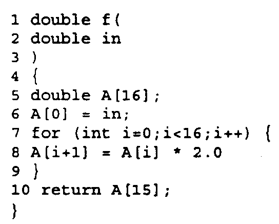
- The indices for array A are now linear index expressions of the loop iterators (the linear expressions are i, i+1 and loop iterator i). The term "linear" as applied to an index expression means that the index expression is the result of a combination of a constant times the iterator plus a constant. This information can be used to determine if multiple iterations of a loop can be run in parallel - referred to as "array privatization." In this example, the compiler can tell that the array value is produced in the previous iteration. It therefore cannot postpone the write operation until after the read of the next iteration.
- Now consider the following example involving an induction variable (which is behaviorally equivalent to the previous example):
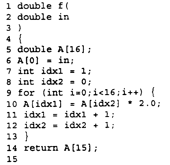
- In this expression, a variable is initialized before a loop. The value used and updated inside the loop is called an induction variable. In some cases the induction variable can be converted into a linear index expression and the parallelism in the code thus exposed. This is the case here because the code is completely equivalent to that of the previous example.
- Known methods of compiler optimization only consider linear index expressions-assuming a worst case of non-parallelism for non-linear expressions. Induction variables are handled by transformation into linear index expressions. Most systems of the prior art use heuristic approaches to obtain memory access information from such expressions. Prior art algorithms formulate the linear index expressions and a specific data flow analysis question as the proof of the existence of a solution of an Integer Linear Programming problem. Another known method for simplifying the Integer Linear Programming problem is Fourier-Motzkin variable elimination, which reduces the number of dimensions of the problem.
- One benefit of the present invention is the ability to perform inter-procedural data flow analysis over multiple function calls. In the prior art, this was done by combining the results of intra- and inter-procedural data flow analysis in a post-processing step. In contrast, the present invention performs operations which flatten the hierarchy of function calls in order to determine data dependencies for memory accesses. Here, the flattening operation is performed prior to the analysis stage.
- These and other advantages of the invention will be apparent from the following description and claims.
- The present invention relates to a method of optimizing the compilation of a computer program. The method includes the steps of identifying an index path by noting the operations of the program which involve one or more index expressions. A non-hierarchical representation of the index path is created. The memory accesses in the non-hierarchical representation of the index path are examined to identify program steps that could be executed in parallel.
- Where the program includes function calls, the step of identifying an index path involves noting operations in the function calls, and the non-hierarchical representation of the index path includes information relating to operations in the function calls.
- In a further embodiment of the invention, the method includes the steps of merging the information relating to operations in the function calls back into a hierarchical representation of the index path.
- In yet a further embodiment, a data structure of the non-hierarchical representation is created and interrogated with questions relating to memory accesses. The results are stored in or back annotated to a question data structure.
- The invention also encompasses an apparatus for compiling computer code including a module which creates a signal flow data structure for index expressions used by the computer code. That module includes a means for identifying steps in the index path of the computer code, identifying parts of memory accessed by index expressions. A module removes the hierarchy from the computer code, creating a non-hierarchical representation of the computer code.
-
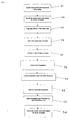
- Fig. 1 is a flowchart showing the basic method of the invention;
- Fig. 2 is a block diagram showing the basic components of the invention and the interactions between them;
- Fig. 3 is a signal flow graph ("SFG") of nodes representing the operations in the pseudo code example in the Detailed Description;
- Fig. 4 is a function call graph for an example in the Detailed Description;
- Fig. 5 is a signal flow graph showing the routing of data and sequence edges for scalar variables in the example in the Detailed Description;
- Fig. 6 is a signal flow graph for the example in the Detailed Description, showing the marking of the index path of the program;
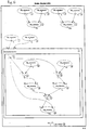
- Fig. 7 is an example of a DFA Problem Graph as used in the present invention;
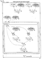
- Fig. 8 is the DFA Problem Graph for the example in the Detailed Description;
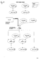
- Fig. 9 is a snapshot of DFA questions for one function call in the example in the Detailed Description;
- Figs. 10-15 are graphical representations showing a set of DFA questions in the context of the DFA Problem Graph shown in Fig. 8, the DFA Question database and the symbolic execution data structure in the example in the Detailed Description.;
- Fig. 16 is the resulting signal flow graph for the example in the Detailed Description, routed with data and sequence edges, and as used to expose parallelism.
-
- The following is a detailed description of the preferred embodiment, which will enable a person of ordinary skill in the art to make and use the invention. The description is intended to be illustrative rather than limiting of the invention, the full scope of which is to be determined by reference to the appended claims and their equivalents. Persons of ordinary skill in the art will recognize that a wide range of alternative embodiments of the invention is encompassed by the invention.
- The invention provides a method and apparatus for efficient compilation of a source code program for use in a computer architecture which produces an efficient compiled code, allowing operations to be executed in parallel, for example in a Very Long Instruction Word ("VLIW") architecture. The aim of the invention is to produce a signal flow graph ("SFG") which exposes as much parallelism in the input source code as possible. An SFG is a data structure representing an algorithm and used to assist in the compilation of code. The SFG is a commonly used and convenient way of representing dependencies in a program by means of data edges (which route data between operations) and sequence edges (which impose order relations between operations) through a program. An example of the use of an SFG data structure is described in DSP Station SFG Concepts and Procedural Interface (Software Version 8.6.1) produced by Frontier Design, b.v.b.a. of Leuven, Belgium. It will be recognized by those of ordinary skill in the art that, the same results can be achieved by other means such as alternative representations of data and sequence information. It is intended that the term SFG imply any such representation.
- The following description assumes source code comprising operations involving scalar and array variables as well as an index path made up of operations that are involved in the computation of indices of memory operation. The basic steps in the data flow analysis are shown in Fig. 1 and are summarized as follows:
- 1. Extract the program operations and the information about the sequence of those operations from the source code (S1).
- 2. Route the control and data edges between operations for scalar variables (S2). Accessing a scalar variable (i.e. reading or writing) consumes (read) or produces (write) the entire variable. Classic data flow analysis can handle this situation. However, classic data flow analysis does not assist in optimization where arrays are concerned, particularly in cases involving non-linear indices.
- 3. Flag all operations in the index path (S3).
- 4. Generate "expansion contexts" (S4). If a function has a function call which has been flagged
in
step 2, then a data structure is generated which enables subsequent stages of the algorithm to "see" that function's operations as if the operations in the function were "inlined" in the calling function's context. - 5. Construct the DFA Problem Graph (S5). This removes and flattens the hierarchies in the index path, for example, due to function calls involving index variables. The DFA Problem Graph has nodes which relate to memory accesses and operations in the index path.
- 6. Create a set of questions relating to memory access ("DFA questions") which can be posed
by the data and sequence flow router in a subsequent phase (S6). The questions are
generated for relevant triplets of loop,
memory access 1 andmemory access 2. These questions are stored in a DFA question database. - 7. Create a symbolic execution data structure (S7). This contains data structures necessary to accumulate or hold information about all memory accesses.
- 8. Perform a symbolic execution of the source code (S8).
- 9. Back annotate the data produced by the symbolic execution to the DFA question data base (S9). In the case of expanded function calls, this stage merges the symbolic execution data generated by all the function invocations.
- 10. Route the control and data edges between operations for array variables using the answers to the DFA questions (S10).
-
- These steps will now be described in detail with particular reference to Fig. 2 and to the following pseudo code which serves as an example to aid in the description of the invention.
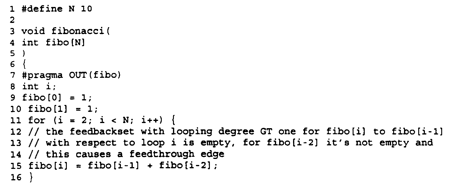

- The following description will make reference to this code and to the representations of data structures which relate to the code. Figs. 5, 6 and 8-16 provide graphical representations of the analysis of the above code using the invention in a manner which will be well understood by persons of ordinary skill in the art.
-
Front end 2 receives thesource code 10 as an input, performs lexical analysis by means ofparser 12 and produces an intermediate level language representation of the source code in the form of annotatedsyntax tree 14. -
Annotated syntax tree 14 is input to SignalFlow Graph Generator 4. SignalFlow Graph Generator 4 first checks the source code to determine if it is capable of synthesis. If so, it traverses the syntax tree (S1 and S2 in Fig. 1) to produce the SFG data structure. -
SFG generator 4 produces the following outputs:Bare SFG 16,Sequence Information 18 andCall Graph 20.Bare SFG 16 is an SFG which represents all the operations insource code 10, but does not include any data or sequence edges linking the operations. The bare SFG thus contains an unscheduled set of operations. An example of a bare SFG can be found in Fig. 3. -
Sequence information 18 is a list which contains information about the lexical order and exclusivity of the different operations in the bare SFG. The exclusivity is derived from conditional statements in the source code. In a language such as C, these are the if-then-else statements, case statements and ? operators. The following is the sequence information for the above mentioned pseudo code example and of bare SFG shown in Fig. 3:
-
Function call graph 20 is a call tree representing function calls insource code 10. It is used in the "flattening" phase and caches information for all function calls in the source code. Every function in the source code is represented by a node in the tree and every function call is represented by an edge. In the bare SFG for the above example shown in Fig. 3, the "fibo" is the only function call. The following is an example of a more complex function call: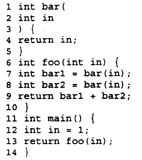
- Fig 4 is the function call graph for the foregoing code. It shows
main program 200 calling function "foo" 202 (represented by edge 201) which in turn calls "bar" 205 twice (represented byedges 203 and 204). -
Bare SFG 16 andsequence information 18 are fed intoscalar router 22. Scalar router provides the routing of edges from one node in the bare SFG to another, using the sequence information 18 (see S2). This is only done for scalar variables. The result of the operation ofscalar router 22 for our example is shown in Fig. 5. It can be seen in Fig. 5 that data and sequence edges have been added, linking all operations which relate to scalar variables. The resultant Scalar Routed SFG is produced at 24. - The non-scalar variables are now addressed. All operations in the index path are now flagged (see S3 in Fig. 1) to prepare for the "flattening" of the function hierarchy. The "index path" is made up of the nodes in the SFG that contribute to index ports on the graph, that is to say, all operations that are involved in the computation of indices used in memory access operations (fetch or store) or if the result is used in another operation which is in the index path. In our example, the index ports are marked with index "i". In cases such as a[i+j], the "+" operation together with the operations defining i and j are tagged as being part of the index path. See the shaded operations shown in Fig. 6.
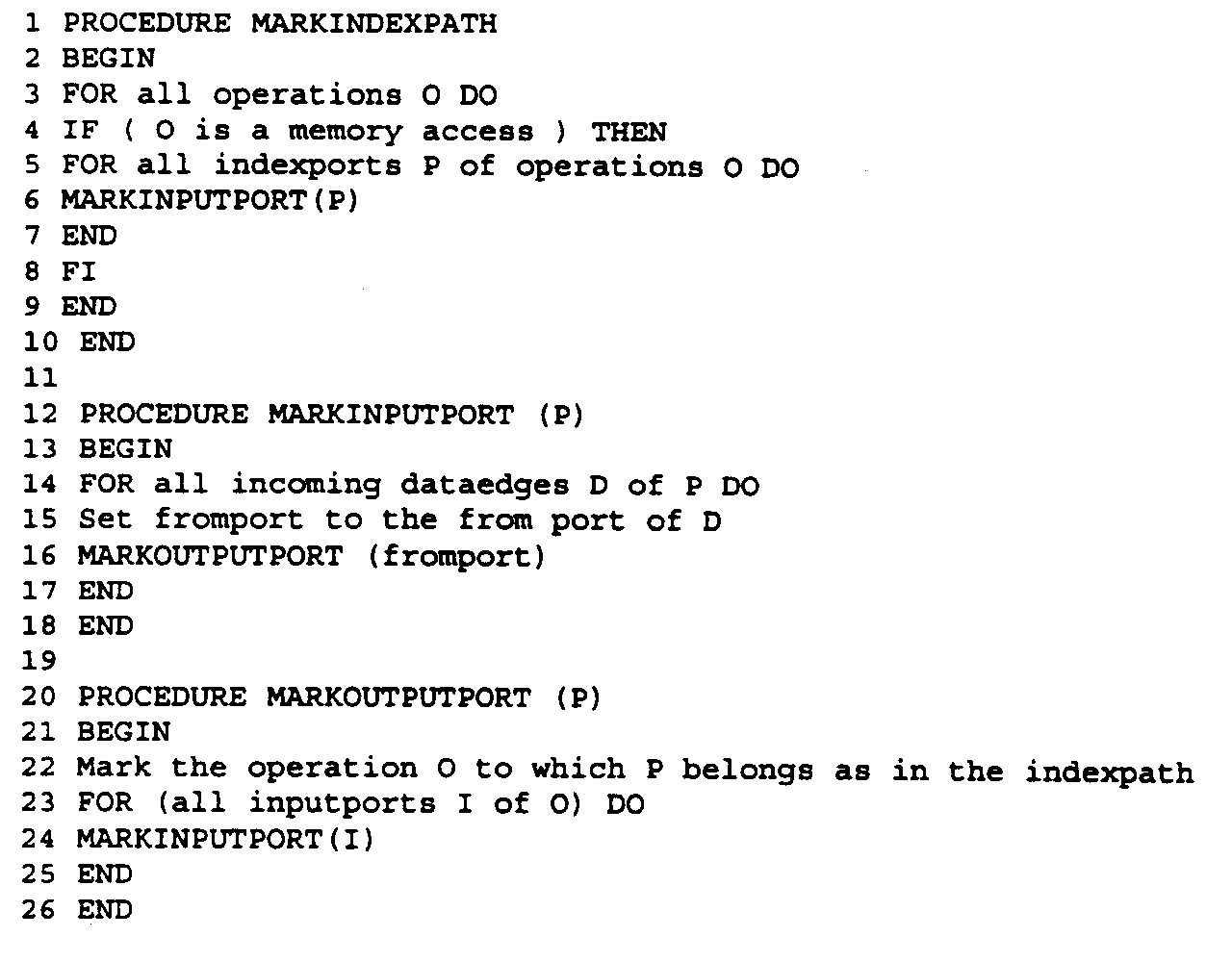
- Each operation has a flag indicating whether or not it is in the index path. The initial value of the flag is "false." Backtracking over the data edges from the index ports of all memory access operations (fetches and stores) will set the appropriate flags. The result of this step is shown for our example in Fig. 6.
- The following pseudo code shows the steps involved in the marking of the index path.
- The next step is the inter-procedural optimization (that is to say, optimization with regard to variables in common between function calls). This involves the step of generation of expansion contexts for the flagged operations (see S4). As a result, every function in the function call
graph data structure 20 will contain a list of "expansion contexts" 26. These are generated as follows: If a function has a function call which was flagged in the previous step (i.e. the marking of the index path), then a data structure is generated (an "expansion context") which prepares to represent the function in a "flat" form - that is to say, expanded in the main program. This is analogous to the C++ concept of an "inlined" function. The result is that the hierarchy of the function calls is removed. That is to say the hierarchy of the function calls involving the index path is flattened. - Each argument in the function call is examined for each call of that function. Note however that only functions with index inputs as arguments are examined. This yields the following information which makes up each expansion context: (1) the parent of the function, (2) the edge which calls the function and (3) a unique identifier for the function. The result is that the program is represented without reference to hierarchies introduced by function calls. DFA problem analysis can be performed on a flat data structure without any function hierarchy.
- The following pseudo code provides an illustration of the generation of an expansion context.

- The next step is the construction of the "DFA Problem Graph" (see S5 in Fig. 1), which describes the source code involved in memory accesses for non-scalar variables. This is performed by
DFA extractor 28. The inputs toDFA extractor 28 are scalar routedSFG 24 and the expansion contexts obtained from the generation ofexpansion contexts 26. In an alternate embodiment, the DFA Extractor utilizes the information in sequenceinformation data structure 18 and bareSFG data structure 16. TheDFA Problem Graph 30 provides a "flat" representation in which hierarchies are removed. TheDFA Problem graph 30 is a graph having nodes related to memory access and operations in the index path. - The starting points for the construction of the DFA Problem Graph are the read memory accesses (fetches) and write memory accesses (stores) in the index path. From these nodes, the data flow is traced back through those nodes that are supported by the symbolic execution engine. The supported index path operations are as follows:
- arithmetic operators: modulo (%), shift left (<<), shift right (>>), divide (/), add (+), casts (type conversions/promotions), subtract (-), multiply (*), bitwise and (&), bitwise inclusive or (|), bitwise exclusive or (^), one's complement operator (∼), unary minus (-), unary plus (+).
- logical operators: less-or-equal (<=), less (<), equal (= =), not equal (!=), greater or equal (>=), greater (>), logical-and (&&), logical or (∥), logical negation (!).
- loop iterators.
- constants.
- bit operators: slice (selecting a range of bits from a given word), setslice (setting a range of bits in a word), concat (appending bits to form a new word).
- look up tables (fetches from constant tables).
- induction variables: variables whose values form an arithmetic progression during the execution of the loop.
- If a node is not supported, then it will not be represented in the DFA Problem Graph and all nodes which depend on the unsupported node will be invalidated. The consequences of this will only be seen later, that is to say, for memory accesses dependent on unsupported nodes worst-case assumptions will be made, possibly restricting the amount of parallelism.
- A DFA Problem Graph is shown in Fig. 7. The graph in Fig. 7 is the DFA Problem Graph for the following pseudo code example:
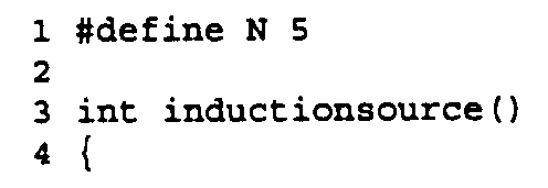 The data structure representing the DFA Problem contains the following components, illustrated in Fig. 7.
-
constant nodes 102, 104 - these are nodes with a single output and a constant inside. - arithmetic and
logical nodes 106, 108 - these are nodes with one or more inputs and an output and which represent the arithmetic and logical operators described above. - top loop 110 - the program itself.
- loop node 112 - these have lower and upper bounds and a step value for the loop iterator. The loop has a nesting edge 114 (to a loop nested in the top loop) which represents the loop hierarchy and a list of induction variables for that loop, represented by induction loop edge 116 (i.e. the loop controls the variable).
- look up table- this is a node representing constant tables and the memory reads (fetches) from those constant tables (not shown in Fig. 7).
- selectors - these are counterparts of if then else statements. They are analogous to hardware multiplexers selecting one of two inputs depending on a boolean selector value (these are not shown in Fig. 8).
- induction variables - induction variables are represented by an induction source node 120 (which holds the value at the start of the loop iteration) and an induction sink 122 (which holds the value at the end of the loop iteration for subsequent use in the following loop iteration).
- memory accesses 124 - this represents the read/write memory accesses (fetches/stores) to variables.
- data edges 126 - these represent the transport of data between nodes.
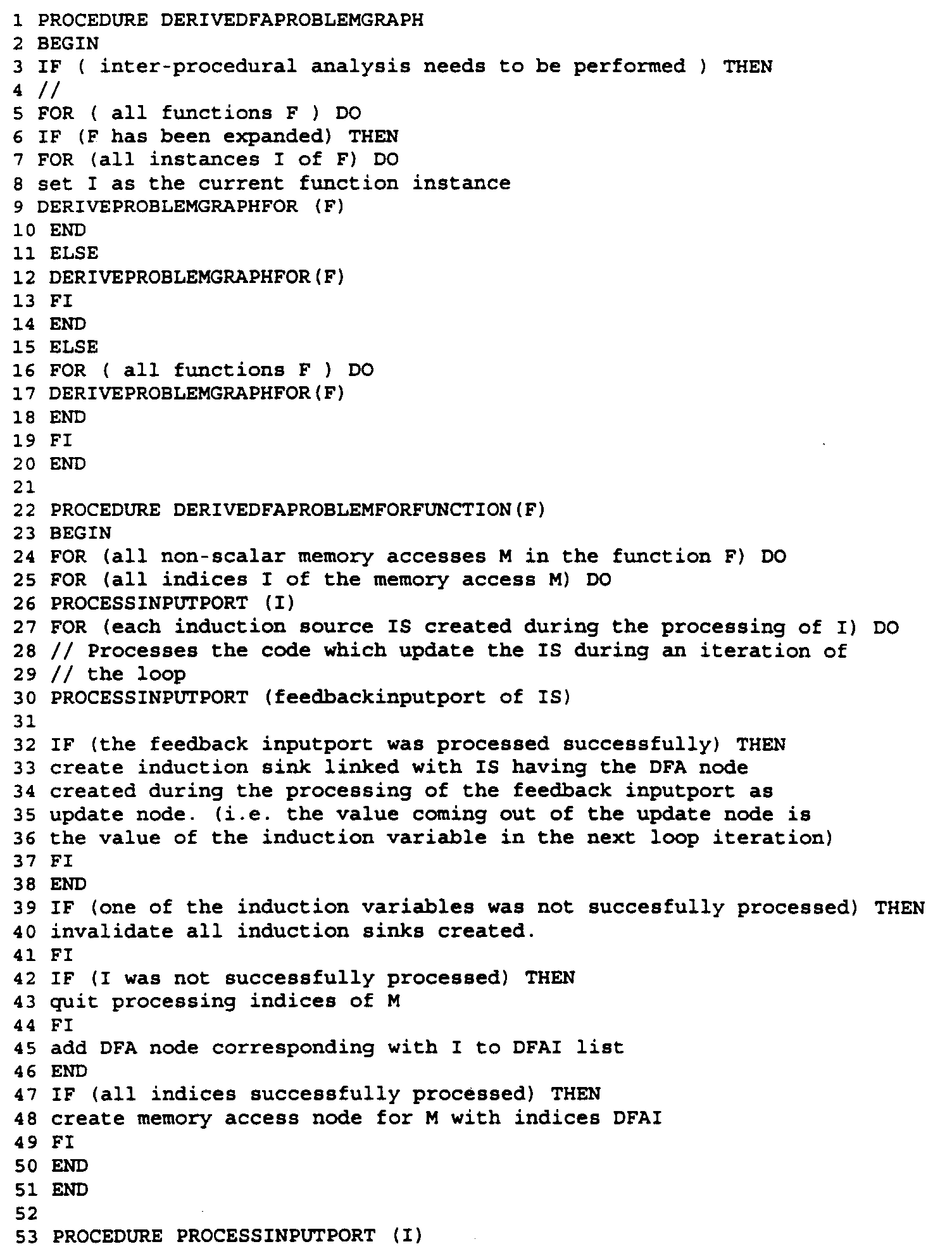
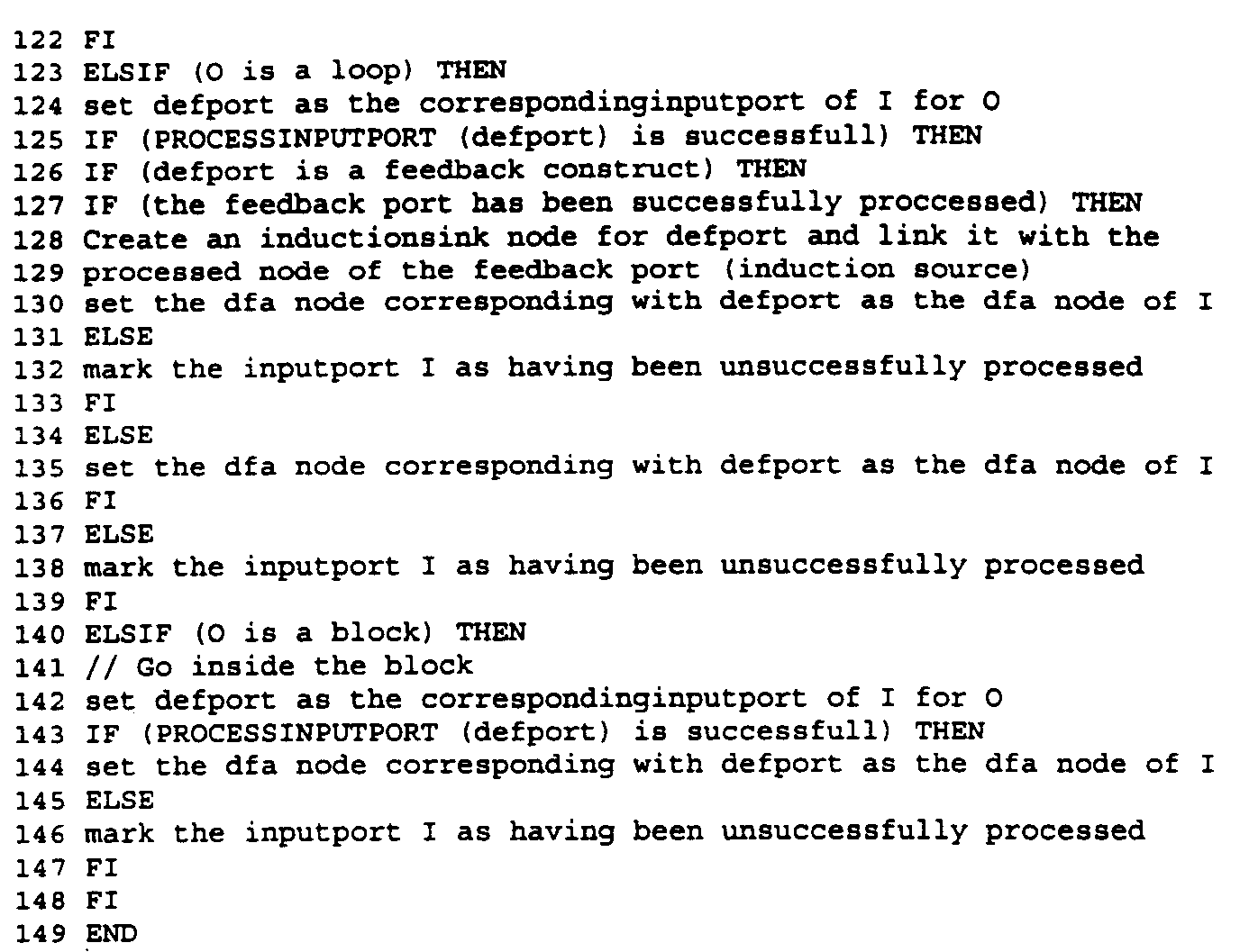
- The DFA Problem Graph for the example code is shown in Fig. 8. The following pseudo code represents the generation of the DFA Problem Graph:

- The next step is the creation of the DFA questions (see S6 in Fig. 1). They are generated by
DFA Question Generator 36 based on information provided byBare SFG 16 andSequence Information 18, and asked for relevant triplets of fetch, store and loop in the index path. The DFA questions are stored in theQuestion Database 32. The questions are aimed at ascertaining whether one operation feeds another (and hence cannot be executed in parallel with that other operation). Once the questions are answered, the bare SFG can be completed with data and sequence edges. The following questions are asked: - does a definition reach a specific point? A definition is killed by another one when
there is no data flow from the killed definition to the points that are reached in the killing
definition. Consider the following examples:
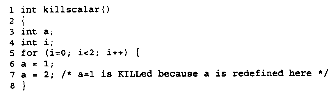 A killed definition can be a "killed scalar definition" for example a=1 and a=2 (a=1 is killed because it is redefined). The following is an example of a non-killed scalar definition:
 A "non-killed scalar definition" occurs when for example a scalar is conditionally updated. The same applies to a "killed array definition," for example a[i]=1 is killed if followed by a[i]=2 in the following code: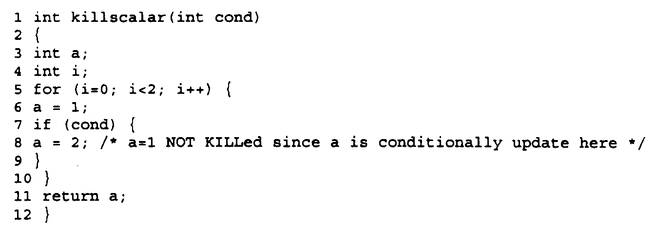
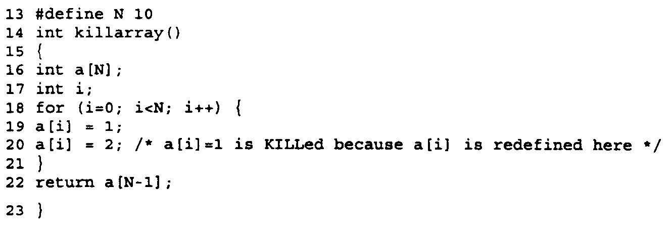
- is a definition a single definition? If an access is defined more than once inside a loop
(over all iterations of the loop), then the definition will possibly overwrite data from
previous iterations in the loop and a feedback sequence edge has to be added to the loop
body. Accesses from future iterations must be performed after the access of the current
iteration. The following is an example involving a single definition:

- are the memory accesses disjoint? If operations act on different parts of the memory
they are disjoint. No sequence or data flow edges must be created. This means that
memory accesses can be performed in parallel. The following is an example involving
disjoint memory accesses:

- does data flow from one iteration to the next iteration? If data produced in one
iteration is consumed in the next iteration, then feedback data edges must be created.
Production in the current iteration must be performed before consumption in the next
iteration or iterations can be performed. The following is an example of feedback
over one iteration.
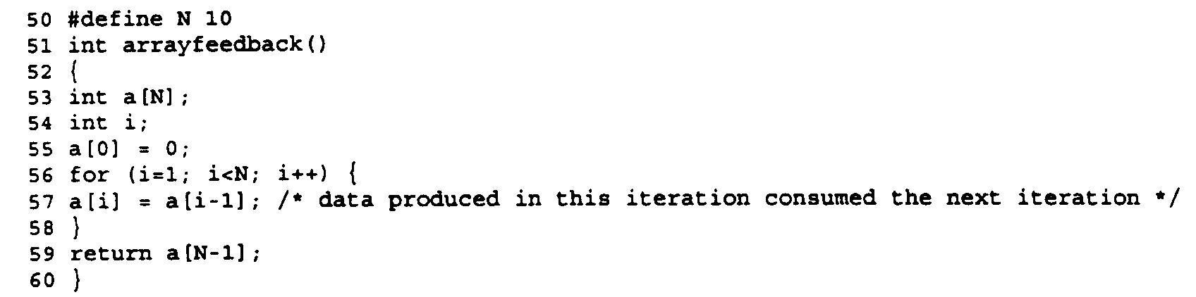
- does data flow from a current iteration to the nth iteration? If data produced in the
current iteration is consumed only in the nth iteration, the data originating at the feedback
source (where n=1) must also be fed forward to the corresponding feedback sink. The
feed forward indicates that data will be used in some next iteration and as such the
production in the current iteration must be performed before consumption in any of the
future iterations can be performed.
The following is an example showing feedback over n iterations where n=2:

- The following is a description of the database structure for the Question Data Base. The answers to the questions can either be boolean yes or no, or a bitvector or index set containing memory locations. The array router uses the answers to these questions to supply data and sequence edges, thus indicating parallelism in the code. Where no answer exists, the worst case is assumed (that is to say the operations cannot be executed in parallel). A snapshot of the questions asked for fibo[i-1] in Sfg_fetchOp in the example illustrated in Figs. 3, 5 and 6 is shown in Fig. 9.
- dfaqSet: This gives all accessed locations for a single memory access.
- dfaqKillSet: This gives the array elements which are always defined for a write memory
access. The dfaqKillSet is computed relative to a loop. Over the entire program the
killset for A[i] is the complete array while the killset relative to a loop is empty. This is
important for determining definitions in a loop nest. Consider the following example:
In this example the store operation at line 5 (A[i]) unconditionally defines all elements of A. The value stored at line 3 (A[0]) can not be accessed since it is killed (overwritten) by the store at line 5(A[i]). In this

example line 3 will be optimized away. dfaqDirectSetIsEmpty: This returns a "true" if two memory accesses do not access the same memory locations during one particular iteration of the loop. Otherwise it returns a "false." Consider the following example:The direct set of the read at line 6 (A[i-1]) with the write at line 7 (A[i]) is empty, since the same memory location is never accessed for a value of the loop iterator i. The direct set between the write at
line 7 and the read atline 8 is not empty. - dfaqFeedbackSetIsEmpty: This returns a "true" is a memory access (fetch/store) uses or defines values used or defined by another memory access in a previous iteration of the loop.
- dfaqFeedbackSetLoopingDegreeGT1IsEmpty: This returns a "true" if a memory access uses values accessed by other memory accesses in an iteration of the loop more than one iteration ago.
- dfaqIsSingleDefinition: This returns a "true" if a memory access in a loop accesses a
memory location only once. Otherwise it returns a "false."
The following pseudo code shows the algorithm for generating the DFA Questions:
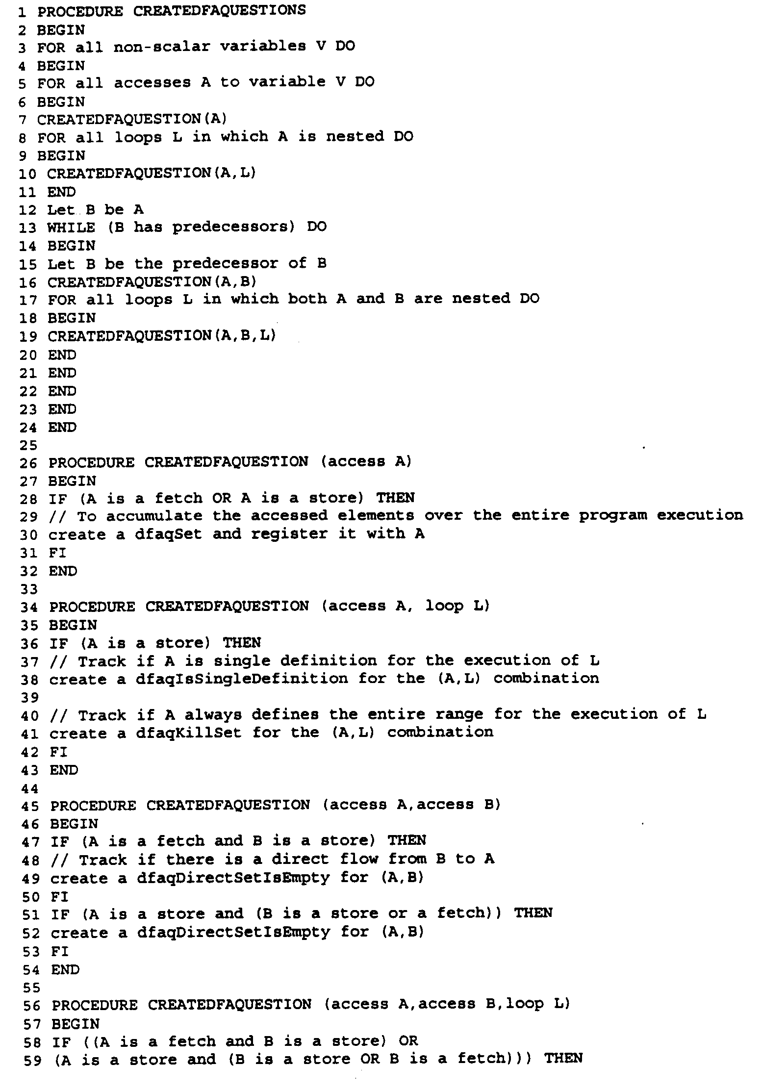
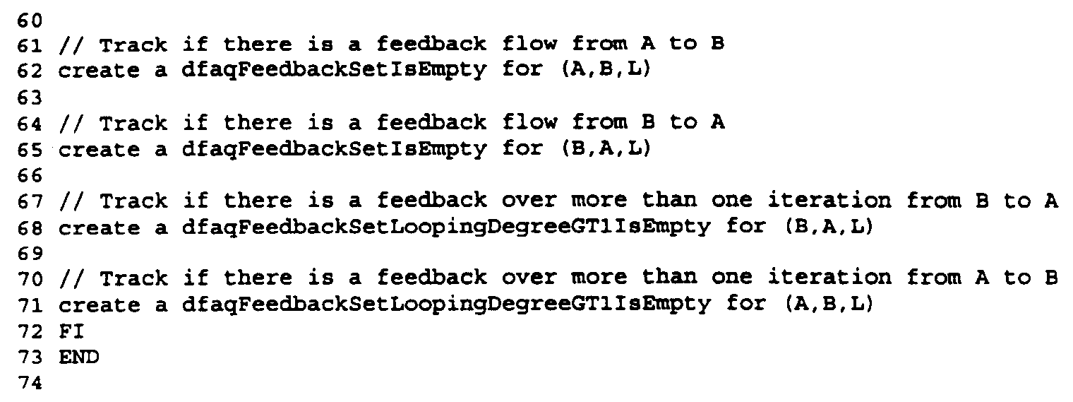
-
- Having generated questions relating to the index path, the next step is a "symbolic execution" which provides answers to those questions (see S8). Prior to the symbolic execution however, a symbolic execution data structure is preferably created by examination of the question data base (see S7).
- The data structure is made up of two parts:
- an execution structure ("symbolic execution structure") linked to the DFA Problem Graph and having the same hierarchy.
- sets used to accumulate data during symbolic execution.
- There are two parts to the symbolic execution data structure (index set database 34): the execution structure linked to the DFA Problem Graph and having the same hierarchy, and the sets used to accumulate index set data during execution. The data structure contains a set of objects containing pointers to memory accesses and index sets plus back pointers to the DFA Problem Graph and the DFA Questions.
- symExecTopLoop: This structure represents and execution of the algorithm. It includes a list of symExecMemoryAccesses and symExecLoops (see below).
- symExecLoop: This structure represents and execution of a loop. It has a list of symExecMemoryAccesses and symExecLoops. It also has a list of induction sources to be updated and lists containing the different sets, each of which must be updated at a particular stage during the execution of a loop iteration.
- symExecMemoryAccess: This structure represents a memory access and has a list of sets which must be updated when a memory access occurs.
- symExecFeedback: This structure represents the induction variables from the DFA Problem Graph.
-
- The Sets are as follows:
- symExecSet: This is a set which is used to collect accessed elements.
- symExecIntegratedset: This is a set made up of two sets, one of which accumulates all the memory accesses that have occurred over the execution of a specific symExec object, for example all memory accesses that occurred during the execution of a particular loop. The other set is similar, but does not include the accessed elements from the previous iteration.
-
- The other sets are directed at the resolution of the questions and make use of a combination of symExecSets, symExecIntegratedSets and other logic to resolve the questions. The sets are:
- symExecAccessedSet which resolves dfaqSet.
- symExecDirectSet which resolves dfaqDirectSetIsEmpty.
- symExecFeedbackSet which resolves dfaqFeedbackSetIsEmpty.
- symExecLoopDegreeGT1Set which resolves dfaqFeedbackSetLoopDegreeGT1IsEmpty.
- symExecKillSet which resolves dfaqKillset.
-
- Figs. 10-14 show a set of DFA questions in the context of the DFA Problem Graph, DFA Question database and the symbolic execution data structure in the example used throughout this Detailed Description.
- The following pseudo code illustrates the creation of the symbolic execution data structures.

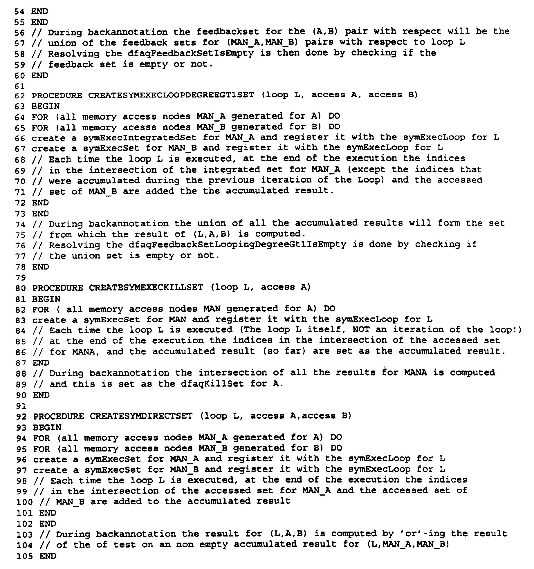
- The next step is the "symbolic execution" of the program (see S8). Fig. 15 shows a snapshot of this procedure, including the symbolic execution data structure and the back-annotation of results to the DFA Question Database 32 (described below). Only those parts of the program that contain loops and index expressions are executed. That is to say a representation of the index expressions is executed. This fills the index sets mentioned above. The execution is performed by
DFA Analyzer 38 which evaluates the data nodes in the DFA Problem Graph (i.e. executing the index path of the program thereby filling the index sets). - The following pseudo code shows the algorithm for the symbolic execution of the program:
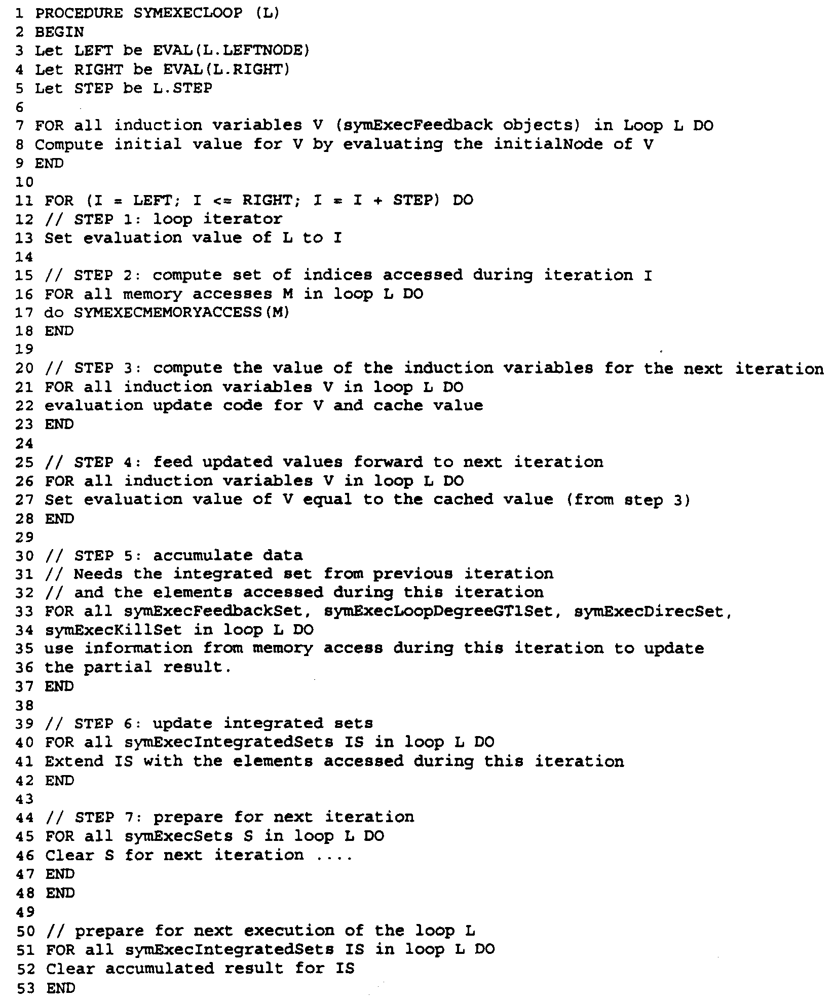

- Finally, the information gathered by the symbolic execution is fed into the
questions database 32. This step is referred to as "back annotation" of the question database (See S9). In the case of non-inter-procedural dataflow analysis, this is done by a simple transfer of data. In the case of inter-procedural dataflow analysis, the data in the different symExec objects is merged to obtain the answers. - This is illustrated in Fig. 15 which shows the progression of the pseudo code example set forth above, the filling of the index sets and the back annotation of index sets to the question database.
- The final SFG shown in Fig. 16 is completed by
array router 40 which adds the data and sequence edges to the scalar routed SFG 24 (See S10). In the case of non-scalar variables, the array router uses the data generated by the dataflow analysis described above or it resorts to worst case scenarios about memory access to the non-scalar variable. - The basic algorithm for the worst case situation is as follows:
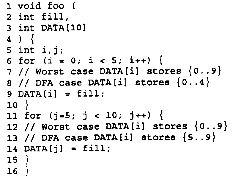
- This is the worst-case scenario assumption referred to above in the discussion of the construction of the DFA Problem Graph. In the worst case scenario, the DATA[i] and DATA[j] operations will have to be sequentialized since their defining (i.e. worst case) sets overlap. If the data from the data flow analysis is taken into account, then the router will not sequentialize the two operations, thus increasing the degree of parallelism since (their defining sets are disjoint).
- The algorithm for the array router is as follows:
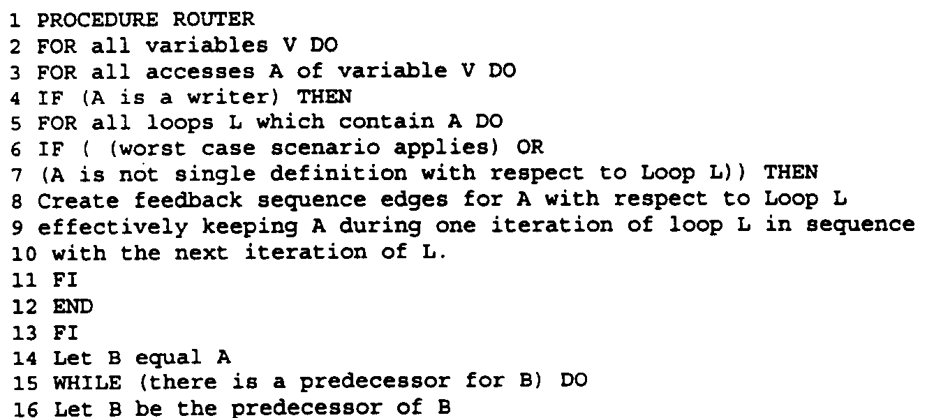


- The output of
array router 40 is a fully routedSFG 42, as shown in Fig. 16. Additional optimization is performed by peephole optimizer 44, which ultimately results infinal SFG 46. Final SFG 46 (and fully routed SFG 42) reflect the operations insource code 10 which can be executed in parallel. The execution ofsource code 10 has thus been optimized. - The foregoing is a description of the preferred embodiment of the invention. Persons of ordinary skill in the art will recognize that a wide variety of alternative and equivalent implementations of the invention are enabled by this description without departing from its spirit and scope.
Claims (10)
- A method of optimizing compilation of a computer program, the program comprising operations involving one or more index expressions, the method comprising the steps of:identifying an index path by noting the operations involving one or more index expressions;creating a non-hierarchical representation of the index path;examining memory accesses in the non-hierarchical representation of the index path to identify program steps that could be executed in parallel.
- The method of claim 1 wherein the program comprises one or more function calls and wherein the step of identifying an index path comprises the step of noting operations in the function calls and wherein the non-hierarchical representation of the index path comprises information relating to operations in the function calls.
- The method of claim 2 further comprising the step of merging the information relating to operations in the function calls back into a hierarchical representation of the index path.
- The method of claim 1 wherein the step of examining memory accesses comprises the step of creating a data structure of the non-hierarchical representation, interrogating the data structure with questions relating to memory accesses and storing results of the step of interrogating in a question data structure.
- The method of claim 2 further comprising the steps of storing the questions relating to memory accesses in a question data structure and wherein the step of storing the results comprises back-annotating the question data structure.
- An apparatus for compiling computer code, the computer code comprising function calls having a hierarchy, the apparatus comprising:
first signal flow analysis means for creating a signal flow data structure for index expression s used by the computer code, wherein the first signal flow analysis means comprises:means for identifying steps in an index path in the computer code, the index path identifying parts of memory accessed by index expressions;means for removing the hierarchy from the computer code, thereby creating a non-hierarchical representation of the computer code. - A method of optimizing compilation of a computer program, the program comprising one or more function calls, operations involving one or more scalars and operations involving one or more index expressions, the method comprising the steps of:determining an index path by flagging the operations involving index expressions;creating a non-hierarchical representation of the index path;generating questions relating to memory accesses by the computer program;creating a symbolic execution data structure comprising information relating to memory accesses by operations involving index expressions;executing the symbolic execution data structure, thereby identifying steps in the program which could be executed in parallel.
- The method of claim 7 further comprising obtaining answers to the questions relating to memory accesses and using the answers to identify parts of the computer program that can be executed in parallel.
- A computer program product directly loadable into the internal memory of a digital computer comprising software code portions for performing the steps of any of claims 1 to 8 when said product is run on a computer.
- A computer arranged to operate according to the method of any of claims 1 to 8.
Applications Claiming Priority (2)
| Application Number | Priority Date | Filing Date | Title |
|---|---|---|---|
| US450329 | 1989-12-11 | ||
| US09/450,329 US6539543B1 (en) | 1999-11-29 | 1999-11-29 | Method and apparatus for compiling source code by flattening hierarchies |
Publications (2)
| Publication Number | Publication Date |
|---|---|
| EP1107115A2 true EP1107115A2 (en) | 2001-06-13 |
| EP1107115A3 EP1107115A3 (en) | 2003-09-03 |
Family
ID=23787662
Family Applications (1)
| Application Number | Title | Priority Date | Filing Date |
|---|---|---|---|
| EP00125079A Ceased EP1107115A3 (en) | 1999-11-29 | 2000-11-17 | Method and apparatus for compiling source code by flattening hierarchies |
Country Status (3)
| Country | Link |
|---|---|
| US (1) | US6539543B1 (en) |
| EP (1) | EP1107115A3 (en) |
| JP (1) | JP2001166946A (en) |
Cited By (1)
| Publication number | Priority date | Publication date | Assignee | Title |
|---|---|---|---|---|
| CN115952230A (en) * | 2022-10-14 | 2023-04-11 | 中南大学 | A Visualization Method of Dynamic Function Call |
Families Citing this family (15)
| Publication number | Priority date | Publication date | Assignee | Title |
|---|---|---|---|---|
| US6966055B2 (en) * | 2001-03-02 | 2005-11-15 | International Business Machines Corporation | Optimizing post-link code |
| US6938046B2 (en) * | 2001-03-02 | 2005-08-30 | Dow Jones Reuters Business Interactive, Llp | Polyarchical data indexing and automatically generated hierarchical data indexing paths |
| US7036116B2 (en) * | 2001-03-23 | 2006-04-25 | International Business Machines Corporation | Percolating hot function store/restores to colder calling functions |
| US6970985B2 (en) | 2002-07-09 | 2005-11-29 | Bluerisc Inc. | Statically speculative memory accessing |
| US7278136B2 (en) * | 2002-07-09 | 2007-10-02 | University Of Massachusetts | Reducing processor energy consumption using compile-time information |
| US6934865B2 (en) * | 2002-07-09 | 2005-08-23 | University Of Massachusetts | Controlling a processor resource based on a compile-time prediction of number of instructions-per-cycle that will be executed across plural cycles by the processor |
| US20050114850A1 (en) | 2003-10-29 | 2005-05-26 | Saurabh Chheda | Energy-focused re-compilation of executables and hardware mechanisms based on compiler-architecture interaction and compiler-inserted control |
| US20050097533A1 (en) * | 2003-10-31 | 2005-05-05 | Chakrabarti Dhruva R. | Run-time performance with call site inline specialization |
| US7996671B2 (en) * | 2003-11-17 | 2011-08-09 | Bluerisc Inc. | Security of program executables and microprocessors based on compiler-architecture interaction |
| US8607209B2 (en) | 2004-02-04 | 2013-12-10 | Bluerisc Inc. | Energy-focused compiler-assisted branch prediction |
| US7464375B2 (en) * | 2004-06-24 | 2008-12-09 | International Business Machines Corporation | Method for flattening hierarchically structured flows |
| US20070294181A1 (en) * | 2006-05-22 | 2007-12-20 | Saurabh Chheda | Flexible digital rights management with secure snippets |
| US20080126766A1 (en) | 2006-11-03 | 2008-05-29 | Saurabh Chheda | Securing microprocessors against information leakage and physical tampering |
| US10095490B2 (en) * | 2016-07-28 | 2018-10-09 | International Business Machines Corporation | System, method and apparatus for preventing vulnerable interleavings in web applications at compile time |
| US11036479B2 (en) * | 2018-08-27 | 2021-06-15 | Georgia Tech Research Corporation | Devices, systems, and methods of program identification, isolation, and profile attachment |
Family Cites Families (10)
| Publication number | Priority date | Publication date | Assignee | Title |
|---|---|---|---|---|
| US5437034A (en) * | 1991-04-19 | 1995-07-25 | Hitachi, Ltd. | Method of generating from source program object program by which final values of variables for parallel execution are guaranteed |
| US5491823A (en) * | 1994-01-25 | 1996-02-13 | Silicon Graphics, Inc. | Loop scheduler |
| US5537620A (en) * | 1994-09-16 | 1996-07-16 | International Business Machines Corporation | Redundant load elimination on optimizing compilers |
| JP3317825B2 (en) * | 1995-09-28 | 2002-08-26 | 富士通株式会社 | Loop-optimized translation processing method |
| US6101488A (en) * | 1996-09-04 | 2000-08-08 | Fujitsu Limited | Intelligent information program generation and retrieval system |
| JP3546341B2 (en) * | 1997-04-17 | 2004-07-28 | 株式会社日立製作所 | Data prefetch method and program generation method for multiple loops |
| US6351845B1 (en) * | 1999-02-04 | 2002-02-26 | Sun Microsystems, Inc. | Methods, apparatus, and articles of manufacture for analyzing memory use |
| US6393423B1 (en) * | 1999-04-08 | 2002-05-21 | James Francis Goedken | Apparatus and methods for electronic information exchange |
| US6374403B1 (en) * | 1999-08-20 | 2002-04-16 | Hewlett-Packard Company | Programmatic method for reducing cost of control in parallel processes |
| US6438747B1 (en) * | 1999-08-20 | 2002-08-20 | Hewlett-Packard Company | Programmatic iteration scheduling for parallel processors |
-
1999
- 1999-11-29 US US09/450,329 patent/US6539543B1/en not_active Expired - Lifetime
-
2000
- 2000-11-17 EP EP00125079A patent/EP1107115A3/en not_active Ceased
- 2000-11-28 JP JP2000361594A patent/JP2001166946A/en active Pending
Non-Patent Citations (2)
| Title |
|---|
| DUESTERWALD E. ET AL: "A Practical Framework for Demand-Driven Interprocedural Data Flow Analysis", ACM TRANSACTIONS ON PROGRAMMING LANGUAGES AND SYSTEMS, vol. 19, no. 6, November 1997 (1997-11-01), pages 992 - 1030 * |
| YUAN LIN AND DAVID PADUA: "Demand-driven interprocedural array property analysis", PROCEEDINGS OF THE 12TH INTERNATIONAL WORKSHOP ON LANGUAGES AND COMPILERS FOR PARALLEL COMPUTING, LCPC'99, 4-6 AUG. 1999, (LECTURE NOTES IN COMPUTER SCIENCE), vol. 1863, August 1999 (1999-08-01) - 2000, pages 303 - 317 * |
Cited By (1)
| Publication number | Priority date | Publication date | Assignee | Title |
|---|---|---|---|---|
| CN115952230A (en) * | 2022-10-14 | 2023-04-11 | 中南大学 | A Visualization Method of Dynamic Function Call |
Also Published As
| Publication number | Publication date |
|---|---|
| US6539543B1 (en) | 2003-03-25 |
| EP1107115A3 (en) | 2003-09-03 |
| JP2001166946A (en) | 2001-06-22 |
Similar Documents
| Publication | Publication Date | Title |
|---|---|---|
| EP1107116A2 (en) | Method and apparatus for compiling source code using symbolic execution | |
| Tate et al. | Equality saturation: a new approach to optimization | |
| US6662354B1 (en) | Determining destinations of a dynamic branch | |
| JP4105264B2 (en) | compiler | |
| US8024718B2 (en) | System and method for optimizing source code | |
| US6539543B1 (en) | Method and apparatus for compiling source code by flattening hierarchies | |
| US20100325608A1 (en) | Generation of parallel code representations | |
| US20080178149A1 (en) | Inferencing types of variables in a dynamically typed language | |
| Flanagan et al. | The semantics of future and an application | |
| Cardoso et al. | Performance‐driven instrumentation and mapping strategies using the LARA aspect‐oriented programming approach | |
| Budiu et al. | Pegasus: An efficient intermediate representation | |
| Vandebon et al. | Enhancing high-level synthesis using a meta-programming approach | |
| Puschner | A tool for high-level language analysis of worst-case execution times | |
| Palmer et al. | Higher-order demand-driven program analysis | |
| Tolmach | Combining closure conversion with closure analysis using algebraic types | |
| Ginsbach | From constraint programming to heterogeneous parallelism | |
| Silber et al. | The Nestor library: A tool for implementing fortran source to source transfromations | |
| de Azevedo | Idempotent backward slices: a gsa-based approach to code-size reduction | |
| Garg et al. | Smaug: Modular augmentation of LLVM for MPC | |
| Kasyanov et al. | Methods and Tools for Constructing Specialized Versions of General-Purpose Cloud Sisal Programs | |
| Wail | Implementing a conventional language for a dataflow architecture | |
| Attali et al. | Optimizing sisal programs: a formal approach | |
| Rupf | Automatic Inference of Stream Semantic Registers in LLVM | |
| Ding et al. | Single Assignment Compiler, Single Assignment Architecture: Future Gated Single Assignment Form*; Static Single Assignment with Congruence Classes | |
| Meier | Compilation for predictable real-time systems |
Legal Events
| Date | Code | Title | Description |
|---|---|---|---|
| PUAI | Public reference made under article 153(3) epc to a published international application that has entered the european phase |
Free format text: ORIGINAL CODE: 0009012 |
|
| AK | Designated contracting states |
Kind code of ref document: A2 Designated state(s): AT BE CH CY DE DK ES FI FR GB GR IE IT LI LU MC NL PT SE TR |
|
| AX | Request for extension of the european patent |
Free format text: AL;LT;LV;MK;RO;SI |
|
| PUAL | Search report despatched |
Free format text: ORIGINAL CODE: 0009013 |
|
| AK | Designated contracting states |
Kind code of ref document: A3 Designated state(s): AT BE CH CY DE DK ES FI FR GB GR IE IT LI LU MC NL PT SE TR |
|
| AX | Request for extension of the european patent |
Extension state: AL LT LV MK RO SI |
|
| 17P | Request for examination filed |
Effective date: 20040127 |
|
| RAP1 | Party data changed (applicant data changed or rights of an application transferred) |
Owner name: ARM BELGIUM NV |
|
| AKX | Designation fees paid |
Designated state(s): DE FR GB IT NL |
|
| 17Q | First examination report despatched |
Effective date: 20061229 |
|
| RAP1 | Party data changed (applicant data changed or rights of an application transferred) |
Owner name: ARM LIMITED |
|
| RAP1 | Party data changed (applicant data changed or rights of an application transferred) |
Owner name: COGNOVO LIMITED |
|
| STAA | Information on the status of an ep patent application or granted ep patent |
Free format text: STATUS: THE APPLICATION HAS BEEN REFUSED |
|
| 18R | Application refused |
Effective date: 20140522 |