EP1107030A1 - Optical ferrule and molding method therefor, and optical connector using this optical ferrule - Google Patents
Optical ferrule and molding method therefor, and optical connector using this optical ferrule Download PDFInfo
- Publication number
- EP1107030A1 EP1107030A1 EP00917381A EP00917381A EP1107030A1 EP 1107030 A1 EP1107030 A1 EP 1107030A1 EP 00917381 A EP00917381 A EP 00917381A EP 00917381 A EP00917381 A EP 00917381A EP 1107030 A1 EP1107030 A1 EP 1107030A1
- Authority
- EP
- European Patent Office
- Prior art keywords
- optical
- ferrule
- concave portion
- flange portion
- molding
- Prior art date
- Legal status (The legal status is an assumption and is not a legal conclusion. Google has not performed a legal analysis and makes no representation as to the accuracy of the status listed.)
- Ceased
Links
- 230000003287 optical effect Effects 0.000 title claims abstract description 179
- 238000000465 moulding Methods 0.000 title claims abstract description 45
- 238000000034 method Methods 0.000 title claims description 30
- 229920005989 resin Polymers 0.000 claims abstract description 27
- 239000011347 resin Substances 0.000 claims abstract description 27
- 239000013307 optical fiber Substances 0.000 claims description 55
- 239000002184 metal Substances 0.000 claims description 34
- 238000003780 insertion Methods 0.000 claims description 26
- 230000037431 insertion Effects 0.000 claims description 26
- 239000000463 material Substances 0.000 claims description 6
- 238000012790 confirmation Methods 0.000 claims description 4
- 238000005498 polishing Methods 0.000 abstract description 15
- 238000012986 modification Methods 0.000 description 15
- 230000004048 modification Effects 0.000 description 15
- 230000004308 accommodation Effects 0.000 description 8
- 230000015572 biosynthetic process Effects 0.000 description 8
- 238000004519 manufacturing process Methods 0.000 description 8
- 239000004734 Polyphenylene sulfide Substances 0.000 description 7
- 229920000069 polyphenylene sulfide Polymers 0.000 description 7
- 239000000853 adhesive Substances 0.000 description 6
- 230000001070 adhesive effect Effects 0.000 description 6
- 238000005520 cutting process Methods 0.000 description 4
- 238000001746 injection moulding Methods 0.000 description 4
- 238000005304 joining Methods 0.000 description 4
- 229920005992 thermoplastic resin Polymers 0.000 description 4
- 239000004033 plastic Substances 0.000 description 3
- 238000001721 transfer moulding Methods 0.000 description 3
- 229920000106 Liquid crystal polymer Polymers 0.000 description 2
- 239000004977 Liquid-crystal polymers (LCPs) Substances 0.000 description 2
- 239000000470 constituent Substances 0.000 description 2
- 238000005336 cracking Methods 0.000 description 2
- 239000003822 epoxy resin Substances 0.000 description 2
- 229920000647 polyepoxide Polymers 0.000 description 2
- OKTJSMMVPCPJKN-UHFFFAOYSA-N Carbon Chemical compound [C] OKTJSMMVPCPJKN-UHFFFAOYSA-N 0.000 description 1
- 239000004593 Epoxy Substances 0.000 description 1
- 229910052799 carbon Inorganic materials 0.000 description 1
- 230000003247 decreasing effect Effects 0.000 description 1
- 230000000694 effects Effects 0.000 description 1
- 239000000835 fiber Substances 0.000 description 1
- 239000000945 filler Substances 0.000 description 1
- 239000011521 glass Substances 0.000 description 1
- LNEPOXFFQSENCJ-UHFFFAOYSA-N haloperidol Chemical compound C1CC(O)(C=2C=CC(Cl)=CC=2)CCN1CCCC(=O)C1=CC=C(F)C=C1 LNEPOXFFQSENCJ-UHFFFAOYSA-N 0.000 description 1
- 230000001771 impaired effect Effects 0.000 description 1
- 239000007924 injection Substances 0.000 description 1
- 238000002347 injection Methods 0.000 description 1
- 230000005226 mechanical processes and functions Effects 0.000 description 1
- 239000003973 paint Substances 0.000 description 1
- 230000002093 peripheral effect Effects 0.000 description 1
- 238000005488 sandblasting Methods 0.000 description 1
- 238000006467 substitution reaction Methods 0.000 description 1
- 230000000007 visual effect Effects 0.000 description 1
- 238000005406 washing Methods 0.000 description 1
Images


Classifications
-
- G—PHYSICS
- G02—OPTICS
- G02B—OPTICAL ELEMENTS, SYSTEMS OR APPARATUS
- G02B6/00—Light guides; Structural details of arrangements comprising light guides and other optical elements, e.g. couplings
- G02B6/24—Coupling light guides
- G02B6/36—Mechanical coupling means
- G02B6/38—Mechanical coupling means having fibre to fibre mating means
- G02B6/3807—Dismountable connectors, i.e. comprising plugs
- G02B6/389—Dismountable connectors, i.e. comprising plugs characterised by the method of fastening connecting plugs and sockets, e.g. screw- or nut-lock, snap-in, bayonet type
- G02B6/3893—Push-pull type, e.g. snap-in, push-on
-
- G—PHYSICS
- G02—OPTICS
- G02B—OPTICAL ELEMENTS, SYSTEMS OR APPARATUS
- G02B6/00—Light guides; Structural details of arrangements comprising light guides and other optical elements, e.g. couplings
- G02B6/24—Coupling light guides
- G02B6/36—Mechanical coupling means
- G02B6/38—Mechanical coupling means having fibre to fibre mating means
- G02B6/3807—Dismountable connectors, i.e. comprising plugs
- G02B6/381—Dismountable connectors, i.e. comprising plugs of the ferrule type, e.g. fibre ends embedded in ferrules, connecting a pair of fibres
- G02B6/3818—Dismountable connectors, i.e. comprising plugs of the ferrule type, e.g. fibre ends embedded in ferrules, connecting a pair of fibres of a low-reflection-loss type
-
- G—PHYSICS
- G02—OPTICS
- G02B—OPTICAL ELEMENTS, SYSTEMS OR APPARATUS
- G02B6/00—Light guides; Structural details of arrangements comprising light guides and other optical elements, e.g. couplings
- G02B6/24—Coupling light guides
- G02B6/36—Mechanical coupling means
- G02B6/38—Mechanical coupling means having fibre to fibre mating means
- G02B6/3807—Dismountable connectors, i.e. comprising plugs
- G02B6/381—Dismountable connectors, i.e. comprising plugs of the ferrule type, e.g. fibre ends embedded in ferrules, connecting a pair of fibres
- G02B6/3818—Dismountable connectors, i.e. comprising plugs of the ferrule type, e.g. fibre ends embedded in ferrules, connecting a pair of fibres of a low-reflection-loss type
- G02B6/3821—Dismountable connectors, i.e. comprising plugs of the ferrule type, e.g. fibre ends embedded in ferrules, connecting a pair of fibres of a low-reflection-loss type with axial spring biasing or loading means
-
- G—PHYSICS
- G02—OPTICS
- G02B—OPTICAL ELEMENTS, SYSTEMS OR APPARATUS
- G02B6/00—Light guides; Structural details of arrangements comprising light guides and other optical elements, e.g. couplings
- G02B6/24—Coupling light guides
- G02B6/36—Mechanical coupling means
- G02B6/38—Mechanical coupling means having fibre to fibre mating means
- G02B6/3807—Dismountable connectors, i.e. comprising plugs
- G02B6/381—Dismountable connectors, i.e. comprising plugs of the ferrule type, e.g. fibre ends embedded in ferrules, connecting a pair of fibres
- G02B6/3825—Dismountable connectors, i.e. comprising plugs of the ferrule type, e.g. fibre ends embedded in ferrules, connecting a pair of fibres with an intermediate part, e.g. adapter, receptacle, linking two plugs
-
- G—PHYSICS
- G02—OPTICS
- G02B—OPTICAL ELEMENTS, SYSTEMS OR APPARATUS
- G02B6/00—Light guides; Structural details of arrangements comprising light guides and other optical elements, e.g. couplings
- G02B6/24—Coupling light guides
- G02B6/36—Mechanical coupling means
- G02B6/38—Mechanical coupling means having fibre to fibre mating means
- G02B6/3807—Dismountable connectors, i.e. comprising plugs
- G02B6/3833—Details of mounting fibres in ferrules; Assembly methods; Manufacture
- G02B6/3865—Details of mounting fibres in ferrules; Assembly methods; Manufacture fabricated by using moulding techniques
-
- G—PHYSICS
- G02—OPTICS
- G02B—OPTICAL ELEMENTS, SYSTEMS OR APPARATUS
- G02B6/00—Light guides; Structural details of arrangements comprising light guides and other optical elements, e.g. couplings
- G02B6/24—Coupling light guides
- G02B6/36—Mechanical coupling means
- G02B6/38—Mechanical coupling means having fibre to fibre mating means
- G02B6/3807—Dismountable connectors, i.e. comprising plugs
- G02B6/3833—Details of mounting fibres in ferrules; Assembly methods; Manufacture
- G02B6/3834—Means for centering or aligning the light guide within the ferrule
- G02B6/3838—Means for centering or aligning the light guide within the ferrule using grooves for light guides
- G02B6/3839—Means for centering or aligning the light guide within the ferrule using grooves for light guides for a plurality of light guides
-
- G—PHYSICS
- G02—OPTICS
- G02B—OPTICAL ELEMENTS, SYSTEMS OR APPARATUS
- G02B6/00—Light guides; Structural details of arrangements comprising light guides and other optical elements, e.g. couplings
- G02B6/24—Coupling light guides
- G02B6/36—Mechanical coupling means
- G02B6/38—Mechanical coupling means having fibre to fibre mating means
- G02B6/3807—Dismountable connectors, i.e. comprising plugs
- G02B6/3869—Mounting ferrules to connector body, i.e. plugs
-
- G—PHYSICS
- G02—OPTICS
- G02B—OPTICAL ELEMENTS, SYSTEMS OR APPARATUS
- G02B6/00—Light guides; Structural details of arrangements comprising light guides and other optical elements, e.g. couplings
- G02B6/24—Coupling light guides
- G02B6/36—Mechanical coupling means
- G02B6/38—Mechanical coupling means having fibre to fibre mating means
- G02B6/3807—Dismountable connectors, i.e. comprising plugs
- G02B6/3873—Connectors using guide surfaces for aligning ferrule ends, e.g. tubes, sleeves, V-grooves, rods, pins, balls
- G02B6/3882—Connectors using guide surfaces for aligning ferrule ends, e.g. tubes, sleeves, V-grooves, rods, pins, balls using rods, pins or balls to align a pair of ferrule ends
Definitions
- the present invention relates to an optical ferrule and a method of molding the same, and to an optical connector using the same.
- an optical connector for connecting multi-core optical fibers an optical connector adopting a pin inserting positioning system, which is called an MT type optical connector and which corresponds to an optical ferrule for use in an optical connector, which is used for an F12 type multi-core optical fiber connector according to JIS C 5981, is known as shown in Figs.
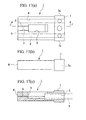
- the conventional optical ferrule 1 (hereinafter referred to as a ferrule 1 for use in an optical connector), which is used as such a kind of MT type optical connector, is a plastic molded article taking a rectangular shape, in which an optical fiber insertion opening portion 2, an optical fiber insertion hole 3, a guide pin hole 4 and an adhesive pouring window 5 are formed, and which has a structure with a square-shaped flange portion 7 provided on the opposite side (right side of Fig. 17) to a connector connecting end face 6.
- a naked optical fiber (not shown) from which a cover is detached is inserted in the optical fiber insertion hole 3, and fixed thereto with adhesive.
- reference numeral 8 shown in Fig. 17(c) denotes a rubber boot for protecting the mouth of the inserted multi-core optical fiber.
- Molding of the ferrule 1 for use in an optical connector is performed by use of transfer molding and injection molding depending on molding resin to be used.
- a gate for injecting molten resin is usually located on a side surface 7a of the flange portion 7.
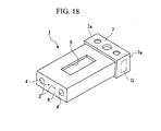
- the position of the gate is illustrated by reference symbol G in Fig. 18. Accordingly, when the metal mold after molding is opened to take out the ferrule 1 for use in an optical connector that is a molded article and the gate G is simply cut with a gate cutter, the gate G remains as a flash on the side surface 7a of the flange portion 7.
- an optical connector (not shown) adopting a plug-adapter-plug system, which corresponds to an F13 type multi-core optical fiber connector according to JIS C 5982, has been known as a so-called an MPO optical connector.
- a plug optical connector constructed by accommodating the ferrule 1 for use in an optical connector in a housing is connected thereto so as to interpose an adapter therebetween. Since the ferrule 1 for use in an optical connector enters a hollow portion of the housing in using the ferrule 1 for use in an optical connector for this MPO optical connector, the flash remaining in the gate G of the flange portion 7 must be removed.
- the flash acts as a hitching member, thus making it impossible for the ferrule 1 for use in an optical connector to be inserted in the housing.
- the flash is caught by the inner wall of the housing, and there is the concern that the ferrule 1 for use in an optical connector cannot slide in the housing smoothly owing to friction caused by hitching of the flash on the inner wall of the housing. Since this flash cannot be removed by sandblasting, a step for polishing the flash is provided, and the flash of the gate G is usually removed by polishing the side surface 7a of the flange portion 7.
- polishing of all of the many ferrules 1 for use in an optical connector has been significantly troublesome. Furthermore, a polishing apparatus exclusively used for polishing the optical connector-use ferrule is needed.
- the present invention was made to overcome the disadvantages of such conventional optical connector-use ferrules.
- the object of the present invention is to provide an optical ferrule capable of saving the labor for removing the flash which remains on the gate in resin molding, and of automatically manufacturing a large number of optical connector-use ferrules without requiring much manpower, and a method of molding the same.
- Another object of the present invention is to provide an optical connector using the optical ferrule.
- An optical ferrule of the present invention has the feature that in a concave portion, a gate in resin molding therein is formed in a ferrule body. According to this constitution of the optical ferrule, a flash which remains after a gate in the concave portion of the optical ferrule that is a molded article after molding is cut by a gate cutter, can be cut readily so as not to protrude to the outside from an opening portion of the concave portion.
- the optical ferrule is accommodated, for example, in the housing of an MPO optical connector, the problem that the flash protrudes from the concave portion and the housing is hitched by the flash never occurs. Therefore, labor for removing the flash by polishing can be saved, and thus productivity of the optical ferrule can be increased, so that it is possible to automatically produce a large number of optical ferrules without requiring much manpower.
- the optical ferrule of the present invention can also have the feature that, as the formation position of the concave portion, it is possible to select any one of the right and left side surfaces of the external periphery surface of the flange portion or both of them, or it is possible to select any one of the upper and lower surfaces of the external periphery surface of the flange portion or both of them.
- the gate must be located at a suitable position in the optical ferrule in consideration of the flow (orientation) of the resin in a metal mold. Specifically, some residual stress occurs in the resin during its cure shrinkage, and the strain becomes large when the optical ferrule is not designed so as to provide an optimum gate position. As a result, there is the concern that warping and cracks may occur.
- the provision of the gate in the flange portion as in the present invention is preferable from the viewpoint of the above circumstances.
- the optical ferrule of the present invention can also have the feature in that when any one of the right and left side surfaces of the external periphery surface of the flange portion is selected in forming the concave portion, the concave portion is formed so as to extend from any one of the side surfaces to a rear end corner portion, and a linear dimension in a connector connecting direction at a portion other than that from any one of the side surfaces to the concave portion is set to 0.3 mm or more.
- the reservation of a linear dimension of 0.3 mm or more in the connector connecting direction makes it possible for a portion of the optical ferrule sliding on an inner wall of the housing to function as a guide in the sliding direction. Consequently, it is possible to prevent a tip portion, where a connector connecting end face is formed, from deflecting in the foregoing right and left directions relative to the connector connecting direction, and the accommodation position of the optical ferrule in the housing can be stably secured.
- the optical ferrule of the present invention makes it possible to also adopt a constitution in which the concave portion is formed between both comer portions of the foregoing side surface.
- the foregoing two comer portions which slide on the inner wall of the housing, can function as a guide in a sliding direction.
- both of the comer portions can function as the long guide in the sliding direction substantially over the whole length of the connector connecting direction on the side surface of the flange portion, which connects between both of the comer portions.
- the tip portion, where the connector connecting end face is formed from deflecting in the right and left direction relative to the connector connecting direction, and the accommodation position of the optical ferrule in the housing can be more stably secured.
- the optical ferrule of the present invention makes it possible to also adopt a constitution in which the concave portion formed in any one of the right and left side surfaces or both of them, or formed in any one of the upper and lower surfaces or both of them, is formed in a groove shape extending over the whole length of the flange portion along the connector connecting direction.
- the optical ferrule of the present invention has a feature in that within the ferrule body there are formed: an optical fiber insertion opening portion serving as an insertion port for the optical fiber; an optical fiber insertion hole opened in a connector connecting end face, the optical fiber insertion hole inserting and positioning the optical fiber; and a hole for a guide pin thereto hole for inserting a guide pin for positioning the ferrule body relative to another ferrule body.
- the optical ferrule of the present invention is suitably used in a state wherein the ferrule of the present invention is accommodated in a housing of an optical connector.
- the optical ferrule of the present invention can adopt also a constitution in which a concave portion, which is related to a material of a ferrule or confirmation factors such as sorts of optical fibers built therein.
- a concave portion As the position of formation of the concave portion in this case, the concave portion should be formed in a flange portion of the ferrule body, and a gate in resin molding should be disposed in the concave portion.
- the material of the ferrule body and the confirmation factors such as the sorts of optical fibers built therein can be confirmed by confirming the concave portion.
- the optical connector of the present invention has a feature that it uses any of the optical ferrules described above. According to this constitution, effects which the optical ferrule possesses can be exerted. It is possible to adopt an optical ferrule in which a concave portion is formed in other portions than a flange portion in addition to the flange portion, and, as a matter of course, an optical connector comprising this optical ferrule can be adopted.
- the method of molding an optical ferrule of the present invention has the feature that a metal mold for forming a ferrule body is used, the ferrule body having a concave portion disposed thereon, in which a gate is disposed in the resin molding, and resin is injected from the gate.
- a flash which is left after the gate of the concave portion in the optical ferrule that is a molded article after molding, can be easily cut so as to have a height lower than an opening portion of the concave portion.
- the problem that the flash protrudes from the concave portion and the housing is hitched by the flash does not occur. Therefore, the labor required to remove this flash by polishing can be saved, and the productivity for manufacturing the optical ferrules can be increased, so that a large number of optical ferrules can be automatically manufactured without requiring much manpower.
- the method of molding an optical ferrule of the present invention may also have the feature that the following are molded by the metal mold: a flange portion which is disposed in a rear end portion opposite to a connector connecting end face so as to protrude to the outside from an external periphery surface of the ferrule body; and the concave portion disposed in an external periphery surface of the flange portion.
- the method of molding an optical ferrule has the feature in that as a formation position of the concave portion in the external periphery surface of the flange portion, any one of the right and left side surfaces of the external periphery surface of the flange portion or both of them can be selected, or any one of the upper and lower surfaces of the external periphery surface of the flange portion or both of them can be selected.
- the gate must be located at a suitable position in the optical ferrule in consideration of the flow (orientation) of the resin in a metal mold. Specifically, some residual stress occurs in the resin during its cure shrinkage, and the strain becomes large when the optical ferrule is not designed so as to provide an optimum position of the gate. As a result, there is the concern that warping and cracking may occur.
- the provision of the gate in the flange portion as in the present invention is preferable from the viewpoint of the above circumstances.
- the method of molding an optical ferrule of the present invention may also have the feature that when any one of the right and left side surfaces of the external periphery surfaces of the flange portion is selected in forming the concave portion, the concave portion is molded so as to extend from the side surface to a rear end comer portion, and the linear dimension in a connector connecting direction at a portion other than that from the side surface to the concave portion is set to 0.3 mm or more.
- the reservation of the linear dimension of 0.3 mm or more in the connector connecting direction makes it possible for a portion of the optical ferrule sliding on an inner wall of the housing to function as a guide in the sliding direction. Consequently, it is possible to prevent a tip portion, where a connector connecting end face is formed, from deflecting in the foregoing right and left directions relative to the connector connecting direction, and the accommodation position of the optical ferrule in the housing can be stably secured.
- the method of molding an optical ferrule of the present invention makes it possible to adopt also a method in which when the concave portion is formed, the concave portion is molded between both corner portions of the foregoing side surface.
- this molding method when this optical ferrule is accommodated in the housing of, for example, the MPO optical connector, the foregoing two comer portions, which slide on the inner wall of the housing, can function as a guide in a sliding direction. Accordingly, both of the comer portions can function as the long guide in the sliding direction substantially over the whole length of the connector connecting direction on the side surface of the flange portion, which connects between both of the corner portions.
- the tip portion, where the connector connecting end face is formed from deflecting in the right and left directions relative to the connector connecting direction, and the accommodation position of the optical ferrule in the housing can be more stably secured.
- the method of molding an optical ferrule of the present invention makes it possible to adopt also a method in which as the shape of the concave portion, the concave portion is formed in a groove shape extending over the whole length of the flange portion along the connector connecting direction by the metal mold. According to this method, since the portion on the external periphery surface of the flange portion other than the concave portion is left over the whole length of the flange portion, that portion can function as a long guide in the connector connecting direction (sliding direction).
- the method of molding an optical ferrule of the present invention is a method of molding the ferrule body in which the following are formed in the ferrule body: an optical fiber insertion opening portion serving as an insertion port for the optical fiber; an optical fiber insertion hole for inserting and positioning the optical fiber, the optical fiber insertion hole being opened to a connector connecting end face and a guide pin hole for inserting a guide pin thereto for positioning the ferrule body relative to another ferrule body.
- this molding method is suitably used in a state where the optical ferrule of the present invention is accommodated in a housing of an optical connector.
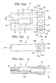
- Figs. 1(a), 1(b) and 1(c) are views showing an embodiment of an optical ferrule of the present invention: Fig. 1(a) is a plan view; Fig. 1(b) is a side view; and Fig. 1(c) is a section view taken along the line A-A of Fig. 1(a).
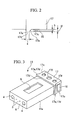
- Fig. 2 is an enlarged view of a portion B of Fig. 1(a), showing the optical ferrule of this embodiment.
- Fig. 3 is a perspective view showing the optical ferrule of this embodiment.
- Fig. 4 is an exploded perspective view showing an example of a metal mold for molding the optical ferrule of this embodiment.
- Fig. 5 is a perspective view showing a state before a plug-adapter-plug connection for connecting RJ optical connectors accommodating the optical ferrule of this embodiment to each other so as to interpose an adapter therebetween.
- Figs. 6(a) and 6(b) show a state before connectors connecting the end faces of the optical ferrules are joined to each other in the plug-adapter-plug connection:
- Fig. 6(a) is a plan section view; and
- Fig. 6(b) is an enlarged view of a portion C of Fig. 6(a).
- Figs. 7(a) and 7(b) are views showing a state where thrust force is caused by joining the connector connecting the end faces of the optical ferrules in the plug-adapter-plug connection:
- Fig. 7(a) is a plan section view; and
- Fig. 7(b) is an enlarged view of a portion D of Fig. 7(a).
- Fig. 8 is a perspective view showing a plug-adapter-plug connection for connecting other RJ optical connectors accommodating the optical ferrule of this embodiment to each other so as to interpose an adapter therebetween.
- Figs. 9(a) and 9(b) show a state before connectors connecting the end faces of the optical ferrules are jointed to each other in the plug-adapter-plug connection:
- Fig. 9(a) is a plan section view; and
- Fig. 9(b) is an enlarged view of a portion E of Fig. 9(a).
- Figs. 10(a) and 10(b) show a state where thrust force is caused by joining the connector connecting end faces of the optical ferrules in the plug-adapter-plug connection:
- Fig. 10(a) is a plan section view; and
- Fig. 10(b) is an enlarged view of a portion F of Fig. 10(a.).
- Fig. 11 is a perspective view showing a plug-adapter-plug connection for connecting MPO optical connectors accommodating the optical ferrules of this embodiment to each other so as to interpose an adapter therebetween.
- Fig. 12 is a plan section view showing a structure of the inside of the MPO optical connector.
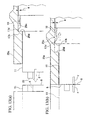
- Figs. 13(a) and 13(b) are views showing an operation of a portion G of Fig. 12 in a plug-adapter-plug connection for jointing the MPO optical connectors:
- Fig. 13(a) is a view showing a state before connectors connecting the end faces of the optical ferrules are joined; and
- Fig. 13(b) is the view showing a state where thrust force is caused after the joining.
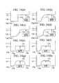
- Figs. 14(a) to 14(h) are partially enlarged plan views of a flange portion corresponding to the portion B of Fig. 1 showing various modifications of a concave portion in the optical ferrule of the present invention.
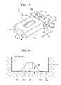
- Fig. 15 is a perspective view showing another modification of the concave portion in the optical ferrule of the present invention.
- Fig. 16 is a partially enlarged view when the concave portion of this modification is viewed from the arrow direction H of Fig. 15.
- Figs. 17(a), 17(b) and 17(c) are views showing a conventional optical ferrule: Fig. 17(a) is a plan view; Fig. 17(b) is a side view; and Fig. 17(c) is a section view taken along the line J-J of Fig. 17(a).
- Fig. 18 is a perspective view showing the conventional optical ferrule.
- Figs. 1(a), 1(b) and 1(c) show an embodiment of an optical ferrule (optical connector-use ferrule) of the present invention
- Fig. 1(a) is a plan view
- Fig. 1(b) is a side view
- Fig. 1(c) is a section view taken along the line A-A of Fig. 1(a).
- Fig. 2 is an enlarged view of the portion B of the optical ferrule in Fig. 1(a)
- Fig. 3 is a perspective view of the optical ferrule of this embodiment.
- the same reference numerals are given to the same constituent components as those in the conventional ferrule 1 for use in an optical connector described in the prior arts.
- this optical ferrule 11 (hereinafter referred to as a ferrule body 11) is a part made of plastic, to which a tip of an optical fiber (not shown) is internally fixed so as to be connected to a connector.
- an optical fiber insertion opening portion 2 serving as an insertion port of the optical fiber
- a pair of optical fiber insertion holes 3 opened in a connector connecting end faces 6, the optical fiber insertion holes 3 inserting and positioning the optical fiber
- a pair of guide pin holes 4 for inserting guide pins (not shown) thereto for use in positioning the ferrule body 11 relative to another ferrule body are inserted
- an adhesive pouring window 5 is a part made of plastic, to which a tip of an optical fiber (not shown) is internally fixed so as to be connected to a connector.
- an optical fiber insertion opening portion 2 serving as an insertion port of the optical fiber
- a pair of optical fiber insertion holes 3 opened in a connector connecting end faces 6, the optical fiber insertion holes 3 inserting and positioning the optical fiber
- the external shape of the ferrule body 11 takes a rectangular shape, and has a structure with a flange portion 17 formed in a rear end portion (the right part of Fig. 1) opposite to a tip end portion of the ferrule body 11 where the connector connecting end face 6 is formed so as to protrude toward the outside from an external peripheral surface 11a of the ferrule body 11.
- the ferrule body 11 is molded by use of transfer molding using epoxy resin such as heat-hardening resin, injection molding using thermoplastic resin such as PPS (polyphenylene sulfide) and LCP (liquid crystal polymer) and other moldings.
- An optical fiber (a single mode or multi mode type naked fiber) from which its cover is detached is inserted in each of the optical fiber insertion holes 3, and is fixed thereto with adhesive.
- Reference numeral 8 shown in Fig. 1(c) denotes a rubber boot for protecting the inserted optical fiber. This rubber boot 8 is used if necessary.
- a concave portion 17c is formed at a position in an external periphery surface of the flange portion 17, where a gate is located in resin molding.
- the flange portion 17 takes a rectangular shape when viewed from the rear end portion toward the connector connecting end face 6, that is, the flange portion 17 takes a rectangular shape in which the two sides parallel to its width direction, i.e., the vertical direction in Fig. 1(a) are longer than the two sides parallel to its thickness direction, i.e., the vertical direction in Fig. 1(b).
- Concave portions 17c are formed in both of the right and left side surfaces 17a of the external periphery surface of the flange portion 17, which are perpendicular to the foregoing width direction of the flange portion 17.
- the formation positions of the concave portions 17c are not limited to this, and a constitution may be adopted in which the concave portion 17c is formed in any one of the upper and lower surfaces of the external periphery surface of the flange portion 17, which are parallel to the foregoing width direction, or formed in both of them.
- another constitution may be adopted in which the concave portion 17c is formed only in any one of the right and left side surfaces 17a of the external periphery surface of the flange portion 17.
- the gate must be located at a suitable position in the ferrule body in consideration of flow (orientation) of the resin in a metal mold. Specifically, some residual stress occurs in the resin during its cure shrinkage, and strain becomes large when the optical ferrule is not designed so as to obtain an optimum position of the gate. As a result, there is the concern that warping and cracking may occur.
- the provision of the gates in both sides of the flange portion 17 as in the present invention is selected from the viewpoint of the above circumstances. Particularly, when injection molding is performed for a thermoplastic resin, shrinkage strain near the gate is large, and hence there is an advantage that the position where the gate is formed can be set apart from the connection end of the ferrule body 11. Furthermore, the provision of the gates in the two positions which are symmetrical with respect to the horizontal direction is effective for decreasing occurrence of stain.
- the respective concave portions 17c are formed in the right and left side surfaces 17a of the flange portion 17, the respective concave portions 17c are formed so as to remove also the rear end comer portions of the side surfaces 17a in the connector connecting direction, and when a linear dimension s (see Fig.
- portion 17d obtained by removing the concave portion 17c from the side surface 17a in the connector connecting direction is set to, for example, 0.3 mm or more, that is, when the portion 17d (hereinafter referred to as a portion 17d) which is adjacent to the shoulder portion 17b of the flange portion 17 in the ferrule body 11 and requires an intrinsic width dimension to function as the flange portion 17 is set to 0.3 mm, or more it is possible to use the ferrule body 11 without any particular problems when the ferrule body 11 is built in, for example, an MPO optical connector.
- the portion 17d sliding on an inner wall of the housing cannot function as a guide in a sliding direction, and a tip portion, where a connector connecting end face 6 is formed, deflects in the right and left directions relative to the connector connecting direction.
- the accommodation position of the ferrule body 11 in the housing cannot be stably secured.
- the foregoing linear dimension s should be reserved to be 0.3 mm or more.
- the position of the concave portion 17c provided in the flange portion 17 not be contiguous with the shoulder portion 17b, but close to the rear end of the ferrule body 11, that is, the rear end surface of the ferrule body 11 on the right side of Figs. 1(a) to (c) and 2.
- the concave portion 17c of the flange portion 17 should be provided at a position which is not in adjacent to the shoulder portion 17b.
- the foregoing shoulder portion 17b of the flange portion 17 is a front wall portion thrusting on an inner wall of the housing when the ferrule body 11 is fitted in the housing, and in a state where the ferrule body 11 is pushed forward in the connector connecting direction by a spring in the housing, the ferrule body 11 thrusts on the inner wall of the housing through the shoulder portion 17b to be positioned in the housing.
- the foregoing right and left side surfaces 17a take a step shape which extends from the portion 17d to the concave portion 17c through a slope surface 17e.
- circular-shaped concave portions 17f are formed in three points as shown in Fig. 3.
- these concave portions 17f are ones on which paint is coated to indicate a relative direction, line numbers and the like between the optical fibers.
- the formation points of the concave portions 17c, their number, and shape may be related to factors such as the material of the ferrule body 11, the sort of the optical fiber built therein and the number of core wires of the optical fiber.
- the concave portion is as well formed in the flange portion 17 of the ferrule body 11, and a gate in resin molding should be disposed in this concave portion.
- the ferrule body 11 (optical ferrule) having the above-described constitution is molded with a metal mold
- the ferrule body 11 should be molded by use of a metal mold 20' in which gates 22b are positioned at positions corresponding to the respective concave portions 17c of the flange portion 17, for example, as shown in Fig. 4.
- This metal mold 20' comprises an upper mold 21, a lower mold 22 and a middle mold 23 sandwiched between the upper and lower molds 21 and 22.
- the lower mold 22 is disposed fixedly, and it is possible to superpose the upper mold 21 on the lower mold 22 by relative movement of the upper mold 21 upward and downward along the direction of the arrow M1.
- the middle mold 23 can slide to the direction of the arrow M2 which is the horizontal direction, in a position at an elevation where the middle mold 23 can be fitted in the lower mold 22.
- the middle mold 23 is a metal mold part constituted by uniting a portion 23a forming the optical fiber insertion opening portion 2 of the ferrule body 11, a pair of pins 23b forming the optical fiber insertion hole 3 and a pair of pins 23c forming the guide pin hole 4.
- a concave portion 21a and a concave portion 22a which form a cavity for the middle mold 23 are formed, respectively. Note that when a molded article molded by the metal mold 20' of Fig. 4 is inverted, the situation shown in Fig. 3 is obtained.
- the gate 22b is formed in each side wall of the lower mold 22, and the gate 22b is formed at a position (a portion 22c forming the side surface of the flange portion 17) corresponding to each of the right and left side surfaces 17a of the flange portion 17 in the ferrule body 11.
- a protrusion portion 22f for forming the foregoing adhesive pouring window 5 and a protrusion portion 22g for forming each of the foregoing concave portions 17f are formed.
- a pair of holes 22d each allowing a tip portion of corresponding one of the pins 23b of the middle mold 23 to be inserted thereinto and supporting the one inserted thereinto; and a pair of holes 22e, each allowing a tip portion of corresponding one of the pins 23c of the middle mold 23 to be inserted thereinto and supporting the one inserted thereinto.
- each gate 22b is provided in the lower mold 22, the gate 22b may be provided in the upper mold 21, or the gate 22b may be provided so as to bestride both of the lower and upper molds 22 and 21.
- metal mold 20' is described as a single-cavity mold in Fig. 4, a multi-cavity mold is usually used.
- the middle mold 23 is slid to move toward the lower mold 22 in the direction of the arrow M2, and then fixed to the lower mold 22 by assembly. Furthermore, the upper mold 21 is moved in the direction of the arrow Ml so as to be superposed thereon, and then fixed. Thereafter, molten resin is injected from the gate 22b. After the molten resin is cured, the upper mold 21 is elevated in the direction of the arrow M1, and the metal mold 20' is opened. The middle mold 23 backs away in the direction of the arrow M2, and the molded article is taken out.
- the foregoing connector connecting surface 6 the concave portions 17c disposed in the external periphery surface of the flange portion 17 so as to correspond to the respective gates 22b, the portions 17d, the optical fiber insertion opening portion 2, the optical fiber insertion holes 3, the guide pin holes 4, the adhesive injection window 5, the concave portions 17f and the like are formed.
- the flash 10 as shown in Figs. 1(a) to Fig. 3 remains.
- the height of the flash 10 (see Fig. 2) remaining after the cutting of the gate with the gate cutter can be lower than the depth H of the concave portion 17c, which is, for example, 0.25 mm, and the cutting of the gate is possible so that the flash 10 can not protrude from the portion 17d.
- the ferrule body 11 undergoes a sandblast treatment, and its parting lines are removed (this sandblast treatment can readily make the surface of the ferrule body 11 smooth, and the sandblast treatment does not affect the sliding of the ferrule body 11 within the housing). Thereafter, the ferrule body 11 requires only washing before use. Accordingly, since it is unnecessary to polish the side surface 17a of the flange portion 17 as has been conventionally done, a large number of ferrule bodies 11 (optical ferrules) can be automatically manufactured without requiring much manpower.
- Fig. 5 is a perspective view showing a plug-adapter-plug connection, in which the RJ optical connector 20, which accommodates the ferrule body 11 of this embodiment obtained by the molding method described above in the housing 20a, is connected to the other ferrule body 11 so as to interpose the adapter 21 therebetween.
- the guide pin 22 is inserted into each of the guide pin holes 4 of the ferrule body 11 only in one of the pair of RJ optical connectors 20.
- the guide pin 22 is not inserted in the other ferrule body 11 (illustrated by chain double-dashed lines), and when both ferrule bodies 11 are connected to each other by thrusting them against each other, the guide pin 22 of one ferrule body 11 is inserted in the guide pin hole 4 of the other ferrule body 11, and a relative positioning of the both ferrule bodies 11 can be performed. Furthermore, a pair of through holes 21a are formed in a wall surface of the adapter 21 in its longitudinal direction, and engaging protrusion portions 20b formed in wall surfaces of the housings 20a engage with the respective through holes 21a, whereby the housings 20 and the adapter 21 are fixedly connected.
- Figs. 6(a) and 6(b) are views showing a state before the connector connecting end faces 6 of the ferrule bodies 11 are joined to each other in the plug-adapter-plug connection.
- Fig. 6(a) is a plan section view
- Fig. 6(b) is an enlarged view of the portion C of Fig. 6(a).
- reference numeral 20f denotes a spring for urging the ferrule body 11 in a direction where the tip portion of the ferrule body 11 protrudes from the housing 20a. As shown in Fig.
- the urging force exerted by the spring 20f is stopped in such a manner that a step difference 20d formed in the inner wall 20c of the housing 20a contacts firmly the shoulder portion 17b of the flange portion 17 of the ferrule body 11. Accordingly, the tip portions of the ferrule bodies 11 in this state are held in a state where the tip portions thereof protrude from the tips of the respective housings 20a.
- a gap having a dimension g is formed for the inner wall surface 20c of the housing 20a, and the flash 10 is made not to contact the inner wall 20c of the housing 20a. Accordingly, in the right and left side surfaces 17a of the flange portion 17 of the ferrule body 11, only the portion 17d contacts the inner wall 20c of the housing 20a.
- Figs. 7(a) and 7(b) are views showing a state where the connector connecting end faces 6 of the ferrule bodies 11 are jointed to each other and a thrust force occurs in the plug-adapter-plug connection.
- Fig. 7(a) is a plan section view
- Fig. 7(b) is an enlarged view of the portion D of Fig. 7(a).
- the shoulder portion 17b of the flange portion 17 of the ferrule body 11 backs away from the foregoing step difference 20d of the housing 20a, the urging force exerted by the foregoing spring 20f is used as thrust force f between the connector connecting end faces 6.
- each of the ferrule bodies 11 moves so as to retreat into the housing 20a in a state where the thrust force f between the connector end faces 6 is kept. Only the portion 17d of the flange portion 17 at this time contacts and slides on the inner wall 20c of the housing 20a as shown in Fig. 7(b). Since the flash 10 still keeps the gap having the foregoing dimension g for the inner wall 20c of the housing 20a and does not contact the inner wall 20c of the housing 20a, the flash 10 never hinders the ferrule body 11 from sliding on the inner wall 20c of the housing 20a.
- Fig. 8 is a perspective view showing a plug-adapter-plug connection, in which another type of RJ optical connectors 23 accommodating the foregoing ferrule bodies 11 are connected so as to interpose an adapter 24 therebetween. Note that, as shown in Fig. 8, the guide pin 22 is inserted into each of the guide pin holes 4 of the ferrule body 11 only in one of the pair of RJ optical connectors 23.
- the guide pin 22 is not inserted into each of the guide pin holes 4 in the other ferrule body 11 (illustrated by chain double-dashed lines), and when the both ferrule bodies 11 are connected to each other by thrusting them against each other, the guide pin 22 of one ferrule body 11 is inserted in the guide pin hole 4 of the other ferrule body 11, and a relative positioning of the both ferrule bodies 11 can be performed. Furthermore, a pair of through holes 24a are formed in wall surfaces of the adapter 24 in its longitudinal direction, and engaging protrusion portions 23b formed in wall surfaces of the housings 23a engage with each other, whereby the housings 23a and the adapter 24 are fixedly connected.
- Figs. 9(a) and 9(b) are views showing the state before the connectors connecting the end faces 6 of the ferrule bodies 11 are joined to each other in the plug-adapter-plug connection.
- Fig. 9(a) is a plan section view
- Fig. 9(b) is an enlarged view of the portion E of Fig. 9(a).
- reference numeral 23f denotes a spring for urging the ferrule body 11 in a direction where the tip portion of the ferrule body 11 protrudes from the housing 23a.
- Fig. 9(b) in the state before the connectors connecting the end faces 6 are joined to each other, shown in Fig.
- the urging force exerted by the spring 23f is stopped in such a manner that a step difference 23d formed in the inner wall 23c of the housing 23a contacts firmly the shoulder portion 17b of the flange portion 17 of the ferrule body 11. Accordingly, the tip portions of the ferrule bodies 11 in this state are held in a state where the tip portions thereof protrude from the tips of the respective housings 23a.
- a gap having a dimension g is formed for the inner wall 23c of the housing 23a, and the flash 10 is made not to contact the inner wall 23c of the housing 23a. Accordingly, in the right and left side surfaces 17a of the flange portion 17 of the ferrule body 11, only the portion 17d contacts the inner wall 23c of the housing 23a.
- Figs. 10(a) and 10(b) are views showing a state where the connector connecting end faces 6 of the ferrule bodies 11 are jointed to each other, and a thrust force occurs.
- Fig. 10(a) is a plan section view
- Fig. 10(b) is an enlarged view of the portion F of Fig. 10(a).
- the shoulder portion 17b of the flange portion 17 of the ferrule body 11 backs away from the foregoing step difference 23d of the housing 23a, the urging force exerted by the foregoing spring 23f is used as thrust force f between the connector connecting end faces 6.
- each of the ferrule body 11 moves so as to retreat into the housing 23a in a state where the thrust force f between the connector end faces 6 is kept. Only the portion 17d of the flange portion 17 at this time contacts and slides on the inner wall 23c of the housing 23a as shown in Fig. 10(b). Since the flash 10 still keeps the gap having the foregoing dimension g for the inner wall 23c of the housing 23a and does not contact the inner wall 23c of the housing 23s, the flash 10 never hinders the ferrule body 11 from sliding on the inner wall 23c of the housing 23c.
- Fig. 11 is a perspective view showing a plug-adapter-plug connection, in which MPO optical connectors 25 accommodating the foregoing ferrule bodies 11 are connected so as to interpose an adapter 26 therebetween. Note that, as shown in Fig. 11, the guide pin 22 is inserted into each of the guide pin holes 4 of the ferrule body 11 only in one of the pair of MPO optical connectors 25.
- the guide pin 22 is not inserted in the other ferrule body 11 (illustrated by chain double-dashed lines), and when the two ferrule bodies 11 are connected to each other by thrusting them against each other, the guide pin 22 of one ferrule body 11 is inserted in the guide pin hole 4 of the other ferrule body 11, and relative positioning of the two ferrule bodies 11 can be performed.
- Fig. 12 is a plan section view showing an internal structure of the MPO optical connector 25 accommodating the foregoing ferrule body 11.
- Figs. 13(a) and 13(b) are views showing an operation of the portion G of Fig. 12 in the plug-adapter-plug connection of the MPO optical connectors 25.
- Fig. 13(a) is a view showing the state before the connectors connecting the end faces 6 of the ferrule bodies 11 are joined to each other
- Fig. 13(b) is a view showing a state where thrust force is caused after joining.
- reference numeral 25f denotes a spring for urging the ferrule body 11 in a direction where the tip portion of the ferrule body 11 protrudes from the housing 25a.
- urging force exerted by the spring 25f is stopped in such a manner that a step difference 25d formed in the inner wall 25c of the housing 25a contacts firmly the shoulder portion 17b of the flange portion 17 of the ferrule body 11. Accordingly, the tip portions of the ferrule bodies 11 in this state are held in a state where the tip portions thereof protrude from the tips of the respective housings 25a.
- the flash 10 still keeps the gap having the foregoing dimension g for the inner wall 25c of the housing 25a and does not contact the inner wall 25c of the housing 25a, the flash 10 never hinders the ferrule body 11 from sliding on the inner wall 25c of the housing 25a in the housing 25a. Accordingly, even if the labor for removing the flash 10 by polishing is eliminated, no problem occurs, so that it is possible to improve productivity of the ferrule body 11 by eliminating the polishing. Specifically, it is possible to automatically manufacture a large number of optical ferrules without much manpower.
- Figs. 14(a) to 14(h) are partially enlarged plan views of the flange portion 17 corresponding to the portion B of Fig. 1. Each arrow shows the gate position.
- the flange portion 17 of Figs. 14(a) to 14(d) has a structure wherein a portion opposite to the foregoing shoulder portion 17b (each of the right parts of Figs. 14(a) to 14(d)) is cut off so as to form a concave portion 17c taking a step shape.
- the concave portion 17c of Fig. 14(a) takes a step shape which runs thereinto from the portion 17d via a step difference wall surface 17h perpendicular to the portion 17d.
- the concave portion 17c of Fig. 14(b) takes the step shape which runs thereinto from the portion 17d via one concave-shaped arc wall surface 17i.
- the concave portion 17c is formed by cutting the foregoing side surface 17a so as to leave the front tip corner portion 17m of the foregoing side surface 17a in the connector connection direction and the rear tip corner portion 17n of the foregoing side surface 17a in the connector connection direction. In other words, only the middle portion of the flange portion 17 is cut to form the groove-shaped concave portion 17c.
- the groove-shaped concave portion 17c in which both walls are perpendicular to the side surface 17a, is formed.
- Fig. 14(e) the groove-shaped concave portion 17c, in which both walls are perpendicular to the side surface 17a, is formed.
- the concave portion 17c in which the edges of the groove are a convex-shaped arc and the bottom of the groove is perpendicular to each edge, is formed.
- the concave portion 17c in which both edges of the groove are a convex-shaped arc and the bottom of the groove is a concave-shaped arc, is formed.
- the concave portion 17c in which the edges of the groove are perpendicular to the side surface 17a and the bottom of the groove is a concave-shaped arc, is formed.
- both of the corner portions 17m and 17n can function as the long guide in the sliding direction substantially over the whole length of the connector connecting direction on the side surface 17a of the flange portion 17, which connects both of the comer portions 17m and 17n.
- the tip portion, where the connector connecting end face 6 is formed from deflecting in the right and left direction relative to the connector connecting direction, and the accommodation position of the optical ferrule 11 in the housing can be more stably secured.
- FIG. 15 is a perspective view of this optical ferrule
- Fig. 16 is a partially enlarged view when the concave portion of the optical ferrule is viewed from the direction of the arrow H. Note that in Figs. 15 and 16, the same constituent components as those of the ferrule body 11 shown in Fig. 3 are denoted by the same reference numerals, and descriptions for them are omitted.
- the concave portion 17c has a constitution in which the concave portion 17c is formed to be groove-shaped so as to extend over the whole length of each side surface 17a of the flange portion 17 along the connector connecting direction. Specifically, the groove-shaped concave portion 17c is formed at a position sandwiched between upper and lower end comer portions 17x and 17y so as to be parallel to the longitudinal direction of the optical ferrule (a longitudinal direction of the ferrule body 11), in the visual line of Fig. 15. Note that the position of the foregoing gate is shown in Fig. 15 by reference symbol G, and the position of the foregoing flash is shown in Fig. 16 by reference numeral 10.
- the foregoing metal mold 20' having the structure in which the ferrule body 11 is sandwiched from the upper and lower sides in the thickness direction as described with reference to Fig. 4 is not used, but a metal mold (not shown) having a parting structure in which a plane including the surface of the shoulder portion 17b of the flange portion 17 is a parting plane should be used.
- a metal mold (not shown) having a parting structure in which a plane including the surface of the shoulder portion 17b of the flange portion 17 is a parting plane should be used.
- the ferrule body 11 is drawn out in the direction of the arrow I of Fig. 15, that is, in the direction parallel to the groove-shaped concave portion 17c, using the foregoing parting plane as a boundary.
- the metal mold having a parting structure is more preferable.
- Fig. 16 shows a partially enlarged view of the foregoing groove-shaped concave portion 17c, viewed from the direction of the arrow H of Fig. 15, when the ferrule body 11 molded in such a manner is accommodated in each of the housings 20a and 23a of the foregoing RJ optical connector 20 and 23 or the housing 25a of the foregoing MPO optical connector 25.
- Fig. 16 when the ferrule body 11 is allowed to slide relative to the various kinds of housings in the perpendicular direction to the drawing of Fig.
- the end face of the flash 10 cut never protrudes from the upper and lower comer portions 17x and 17y to the outside, and hence the gap having the dimension g can be kept between the inner surface of each of the various kinds of housings and the end face of the flash 10, so that hitching on the flash never occurs. Accordingly, also in the optical ferrule of this modification, polishing of the side surface 17a of the flange portion 17 that has been heretofore performed is unnecessary, and a large number of ferrule bodies 11 (optical ferrule) can be automatically manufactured without requiring much manpower.
- the foregoing upper and lower corner portions 17x and 17y remain over the whole length of the flange portion 17 in this modification, the foregoing upper and lower corner portions 17x and 17y can function as a long guide in the connector connecting direction (sliding direction). Therefore, it is possible to prevent the tip portion, where the connector connecting end face 6 is formed, from deflecting in the right and left directions relative to the connector connecting direction more effectively, and the accommodation position of the optical ferrule 11 in the housing can be stably secured.
- a groove-shaped concave portion 17c is formed in each of both side surfaces 17a
- the formation position of the concave portion 17 is not limited to this, and a constitution in which the concave portion 17c is formed only in any one of both side surfaces 17a may be adopted.
- a constitution in which the groove-shaped concave portion 17c is formed in each of the foregoing upper and lower surfaces of the flange portion 17 or in any one of both of the foregoing upper and lower surfaces thereof, may be adopted.
- ferrule body 11 optical ferrule
- ferrule body 11 of this embodiment and the ferrule body 11 of each modification were described for a two-core optical ferrule, the number of cores of the optical fibers is an optional value such as four and eight.
- the ferrule body 11 may also be applied to a single-core optical ferrule if necessary.
- ferrule body 11 optical ferrule
- ferrule body 11 of this embodiment and the ferrule body 11 of each modification have been described using the MT type ferrule body as an example, the present invention is not limited to this, and the present invention may be applied to another type of optical ferrule.
- a PPS thermoplastic resin containing filler should be adopted because of its applicability to continuous injection molding, in order to increase the manufacturing efficiency.
- heat-hardening resin such as epoxy
- transfer molding is often used in general, and the manufacturing steps become somewhat complicated as compared to PPS resins, resulting in comparatively low manufacturing efficiency.
- PPS thermoplastic resin is more preferable.
- epoxy resins and PPS resins show become black by adding carbon thereto, and there is little difference between their appearances. Therefore, for example, existence of the concave portion 17c can be used as an identification mark for indicating that the ferrule body is formed of a PPS resin.
- optical fibers formed of glass not only optical fibers formed of glass, but also optical fibers formed of plastic are included.
- each concave portion 17c and the gate G are provided in each of side surface of the flange portion 17, the constitution of the ferrule body 11 is not limited to this, but each concave portion 17c and the gate G may be formed any one of the both sides of the flange portion 17.
- the position of the concave portion where the gate is disposed exists in the flange portion.
- the gist of the present invention is to locate the position of the gate in the concave portion, the position of the concave portion is not always limited in the flange portion.
- the concave portion may be provided at an optional position.
Landscapes
- Physics & Mathematics (AREA)
- General Physics & Mathematics (AREA)
- Optics & Photonics (AREA)
- Mechanical Coupling Of Light Guides (AREA)
- Moulds For Moulding Plastics Or The Like (AREA)
- Injection Moulding Of Plastics Or The Like (AREA)
Abstract
Description
Claims (24)
- An optical ferrule wherein a concave portion (17c) in which a gate (G) in resin molding is disposed is formed in a body (11).
- The optical ferrule according to claim 1, wherein in said ferrule body (11), there are formed an optical fiber insertion opening portion (2) for inserting an optical fiber therein, an optical fiber insertion hole (3) opened in a connector connecting end face (6), the optical fiber insertion hole (3) inserting said optical fiber therein and positioning said optical fiber, and a guide pin hole (4) for inserting a guide pin (22) therein, the guide pin (22) positioning said ferrule bodies (11).
- The optical ferrule according to claim 2, wherein a flange portion (17) protruding from an external periphery surface of said ferrule body to the outside is provided in a rear end portion opposite to said connector connecting end face, and said concave portion is formed in an external surface of said flange portion.
- The optical ferrule according to claim 3, wherein said flange portion has a rectangular shape when viewed from said rear end portion toward said connector connecting end face, and said concave portion is formed in each of right and left side surfaces (17a) of the external periphery surface of said flange portion or in any one of the right and left side surfaces thereof.
- The optical ferrule according to claim 4, wherein said concave portion is formed so as to extend from said side surface to a rear end corner portion.
- The optical ferrule according to claim 5, wherein a linear dimension (s) of said flange portion obtained by excluding said concave portion is set to 0.3 mm or more.
- The optical ferrule according to claim 4, wherein said concave portion is formed between both corner portions (17m, 17n) of said side surface.
- The optical ferrule according to claim 4, wherein said concave portion is formed in a groove shape extending over the whole length of said flange portion in a connector connecting direction.
- The optical ferrule according to claim 3, wherein said flange portion has a rectangular shape when viewed from said rear end portion toward said connector connecting end face, and said concave portion is formed in each of upper and lower side surfaces (17a) of the external periphery surface of said flange portion or in any one of the upper and lower side surfaces thereof.
- The optical ferrule according to claim 9, wherein said concave portion is formed in a groove shape extending over the whole length of said flange portion along a connector connecting direction.
- An optical ferrule wherein a concave portion (17c) related to a material of a ferrule body (11) and confirmation factors such as sorts of an optical fiber built in said ferrule body is formed.
- The optical ferrule according to claim 11, wherein said concave portion is formed in a flange portion (17) of said ferrule body, and a gate (G) in resin molding is disposed in said concave portion.
- The optical ferrule according to claim 11, wherein said concave portion is formed at a portion other than the flange portion.
- An optical connector using the optical ferrule according to any one of claims 1 to 13.
- A method of molding an optical ferrule wherein used is a metal mold (20) in which a concave portion (17c), where a gate (G) in resin molding is disposed, is formed in a ferrule body (11), and resin is injected from said gate.
- The method of molding an optical ferrule according to claim 15, wherein in said ferrule body (11) molded is said optical ferrule in which an optical fiber insertion opening portion (2) for inserting an optical fiber therein, an optical fiber insertion hole (3) opened in a connector connecting end face (6), the optical fiber insertion hole (3) inserting said optical fiber therein and positioning said optical fiber, and a guide pin hole (4) for inserting a guide pin (22) therein, the guide pin (22) positioning said ferrule bodies (11).
- The method of molding an optical ferrule according to claim 16, wherein by said metal mold, a flange portion (17) disposed at a rear end portion opposite to said connector connecting end face, the flange portion (17) being formed so as to protrude from an external periphery surface of said ferrule body to the outside; and said concave portion disposed in an external periphery surface of said flange portion are molded.
- The method of molding an optical ferrule according to claim 17, wherein by said metal mold, said flange portion is molded to a shape taking a rectangular shape when viewed from said rear end portion toward said connector connecting end face, and said concave portion is molded in each of right and left side surfaces (17a) of the external periphery surface of said flange portion or in any one of the right and left side surfaces thereof.
- The method of molding an optical ferrule according to claim 18, wherein by said metal mold, said concave portion is formed so as to extend from said side surface to said rear end corner portion.
- The method of molding an optical ferrule according to claim 19, wherein by said metal mold, a linear dimension (s) of said flange portion obtained by excluding said concave portion is molded to 0.3 mm or more.
- The method of molding an optical ferrule according to claim 18, wherein by said metal mold, said concave portion is molded between both corner portions (17m, 17n) of said side surface.
- The method of molding an optical ferrule according to claim 18, wherein by said metal mold, said concave portion is formed to a groove shape extending over the whole length of said flange portion in a connector connecting direction.
- The method of molding an optical ferrule according to claim 17, wherein by said metal mold, said flange portion is molded so as to take a rectangular shape when viewed from said rear end portion toward said connector connecting end face, and said concave portion is molded in each of upper and lower side surfaces of the external periphery surface of said flange portion or in any one of the upper and lower side surfaces thereof.
- The method of molding an optical ferrule according to claim 23, wherein by said metal mold, said concave portion is formed in a groove shape extending over the whole length of said flange portion along a connector connecting direction.
Applications Claiming Priority (5)
| Application Number | Priority Date | Filing Date | Title |
|---|---|---|---|
| JP11586799 | 1999-04-23 | ||
| JP11586799 | 1999-04-23 | ||
| JP2000095908 | 2000-03-30 | ||
| JP2000095908A JP4361193B2 (en) | 1999-04-23 | 2000-03-30 | Optical ferrule and optical connector using this optical ferrule |
| PCT/JP2000/002582 WO2000065392A1 (en) | 1999-04-23 | 2000-04-20 | Optical ferrule and molding method therefor, and optical connector using this optical ferrule |
Publications (2)
| Publication Number | Publication Date |
|---|---|
| EP1107030A1 true EP1107030A1 (en) | 2001-06-13 |
| EP1107030A4 EP1107030A4 (en) | 2005-08-10 |
Family
ID=26454291
Family Applications (1)
| Application Number | Title | Priority Date | Filing Date |
|---|---|---|---|
| EP00917381A Ceased EP1107030A4 (en) | 1999-04-23 | 2000-04-20 | Optical ferrule and molding method therefor, and optical connector using this optical ferrule |
Country Status (6)
| Country | Link |
|---|---|
| US (1) | US7232261B1 (en) |
| EP (1) | EP1107030A4 (en) |
| JP (1) | JP4361193B2 (en) |
| AU (1) | AU3840500A (en) |
| CA (1) | CA2335839C (en) |
| WO (1) | WO2000065392A1 (en) |
Families Citing this family (8)
| Publication number | Priority date | Publication date | Assignee | Title |
|---|---|---|---|---|
| US6676299B1 (en) * | 2002-11-08 | 2004-01-13 | Stratos Lightwave, Inc. | Device having multiple optical fibers |
| EP2230542A1 (en) * | 2009-03-16 | 2010-09-22 | Tyco Electronics Nederland B.V. | Assembly with an optical fiber alignment |
| JP2014106409A (en) | 2012-11-28 | 2014-06-09 | International Business Maschines Corporation | Connector for multilayered optical waveguide |
| JP2016095410A (en) * | 2014-11-14 | 2016-05-26 | 住友電気工業株式会社 | Grin lens array, connector with lens, and connector system with lens |
| US20230141449A1 (en) * | 2020-03-27 | 2023-05-11 | Sumitomo Electric Industries, Ltd. | Optical connection structure, ferrule, and optical connector |
| JPWO2022113418A1 (en) | 2020-11-24 | 2022-06-02 | ||
| CN115803664A (en) | 2020-11-24 | 2023-03-14 | 株式会社藤仓 | Ferrules for Optical Connectors |
| WO2024143179A1 (en) * | 2022-12-28 | 2024-07-04 | 株式会社フジクラ | Ferrule for optical fiber and ferrule with optical fiber |
Family Cites Families (16)
| Publication number | Priority date | Publication date | Assignee | Title |
|---|---|---|---|---|
| JPS5674212A (en) | 1979-11-22 | 1981-06-19 | Fujitsu Ltd | Connection method for optical fiber |
| JPS5767906A (en) * | 1980-10-14 | 1982-04-24 | Nippon Telegr & Teleph Corp <Ntt> | Mold forming method for terminal part of optical fiber |
| JPS61137109A (en) | 1984-12-07 | 1986-06-24 | Sumitomo Electric Ind Ltd | Optical connector ferrule and its production |
| JPS6316112A (en) | 1986-07-07 | 1988-01-23 | Odai Tekko Kk | Tappet mechanism with valve stroke holding device for internal combustion engine |
| JPS6316112U (en) * | 1986-07-18 | 1988-02-02 | ||
| JPH0216021A (en) | 1988-07-04 | 1990-01-19 | Mitsubishi Cable Ind Ltd | Ferrule injection molding die |
| US4911518A (en) * | 1989-03-09 | 1990-03-27 | Amp Incorporated | Threaded front end connector for optical fiber and method of making same |
| JPH0477419A (en) | 1990-07-17 | 1992-03-11 | Teisan Seiyaku Kk | Formulation for patching |
| JPH0477419U (en) * | 1990-11-19 | 1992-07-07 | ||
| JP2893231B2 (en) | 1993-08-12 | 1999-05-17 | 株式会社フジクラ | Ferrule for optical connector and manufacturing method thereof |
| US5381500A (en) * | 1993-10-12 | 1995-01-10 | The Whitaker Corporation | Metal insert and buffer retention plunger |
| EP1130435A1 (en) * | 1997-02-21 | 2001-09-05 | Nippon Telegraph and Telephone Corporation | Plastic ferrule for optical connector |
| AU5180798A (en) | 1997-07-23 | 1999-02-16 | Minnesota Mining And Manufacturing Company | Optical fiber retention and strain relief collar |
| US5923803A (en) * | 1997-07-28 | 1999-07-13 | Molex Incorporated | Method of fabricating a fiber optic connector ferrule |
| JPH1172651A (en) | 1997-08-28 | 1999-03-16 | Sumitomo Electric Ind Ltd | Manufacturing method of optical connector ferrule |
| CA2262351A1 (en) | 1998-02-24 | 1999-08-24 | Jds Fitel Inc. | Tunable multiple fiber optical connector |
-
2000
- 2000-03-30 JP JP2000095908A patent/JP4361193B2/en not_active Expired - Lifetime
- 2000-04-20 EP EP00917381A patent/EP1107030A4/en not_active Ceased
- 2000-04-20 AU AU38405/00A patent/AU3840500A/en not_active Abandoned
- 2000-04-20 US US09/720,235 patent/US7232261B1/en not_active Expired - Lifetime
- 2000-04-20 CA CA002335839A patent/CA2335839C/en not_active Expired - Lifetime
- 2000-04-20 WO PCT/JP2000/002582 patent/WO2000065392A1/en not_active Ceased
Also Published As
| Publication number | Publication date |
|---|---|
| CA2335839A1 (en) | 2000-11-02 |
| WO2000065392A8 (en) | 2001-03-01 |
| US7232261B1 (en) | 2007-06-19 |
| CA2335839C (en) | 2005-10-04 |
| WO2000065392A1 (en) | 2000-11-02 |
| EP1107030A4 (en) | 2005-08-10 |
| JP4361193B2 (en) | 2009-11-11 |
| AU3840500A (en) | 2000-11-10 |
| JP2001004872A (en) | 2001-01-12 |
Similar Documents
| Publication | Publication Date | Title |
|---|---|---|
| US8562225B2 (en) | Optical ferrule, optical ferrule molding die, manufacturing method of optical ferrule, and ferrule with optical fiber | |
| CN101523263B (en) | Ferrule, method of manufacturing optical waveguide connector using the ferrule, and optical waveguide connector | |
| US20100215319A1 (en) | Multi-Fiber Ferrule with Integrated, Molded Guide Pin | |
| US7588374B2 (en) | Optical ferrule and manufacturing method thereof | |
| TWI844131B (en) | Sleeve, optical connector and method for manufacturing the sleeve | |
| US7232261B1 (en) | Optical ferrule and molding method therefor, and optical connector using this optical ferrule | |
| WO2018168141A1 (en) | Method for manufacturing optical connector ferrule, optical connector ferrule, and optical fiber with connector | |
| JPH04315111A (en) | Optical connector | |
| US8235700B2 (en) | Mold for forming an optical fiber connector | |
| JP2009251603A (en) | Optical fiber connector | |
| CN102248637A (en) | Die for molding fiber coupling connector | |
| JP2004109398A (en) | Ferrule for optical connector and method of manufacturing the same | |
| US6702962B2 (en) | Manufacturing method of ferrule for multi optical connector | |
| EP4625013A1 (en) | Ferrule, optical connector, and method for manufacturing optical connector | |
| CN216718747U (en) | Core inserting die | |
| JP3689859B2 (en) | Ferrule for optical connector | |
| JP2001108867A (en) | Ferrule for multi-core optical connector | |
| JP4043023B2 (en) | Ferrule for optical connector | |
| JP5395581B2 (en) | Multi-fiber optical connector | |
| JP4105028B2 (en) | Optical connector | |
| JP3982063B2 (en) | Manufacturing method of optical fiber connector | |
| JP5307484B2 (en) | Optical ferrule and manufacturing method thereof | |
| JP2002506996A (en) | Ferrules to support some optical waveguides | |
| JP2007212600A (en) | Optical connector molding die and optical connector ferrule manufactured thereby | |
| CN102371653A (en) | Die used for moulding fiber coupling connector |
Legal Events
| Date | Code | Title | Description |
|---|---|---|---|
| PUAI | Public reference made under article 153(3) epc to a published international application that has entered the european phase |
Free format text: ORIGINAL CODE: 0009012 |
|
| 17P | Request for examination filed |
Effective date: 20010104 |
|
| AK | Designated contracting states |
Kind code of ref document: A1 Designated state(s): AT BE CH CY DE DK ES FI FR GB GR IE IT LI LU MC NL PT SE |
|
| RBV | Designated contracting states (corrected) |
Designated state(s): DE FR GB |
|
| RIC1 | Information provided on ipc code assigned before grant |
Ipc: 7G 02B 6/38 A Ipc: 7B 29D 11/00 B |
|
| A4 | Supplementary search report drawn up and despatched |
Effective date: 20050623 |
|
| STAA | Information on the status of an ep patent application or granted ep patent |
Free format text: STATUS: THE APPLICATION HAS BEEN REFUSED |
|
| 18R | Application refused |
Effective date: 20070806 |