EP1106928B1 - Method for staging fuel for gas turbines utilizing both gaseous and liquid fuels - Google Patents
Method for staging fuel for gas turbines utilizing both gaseous and liquid fuels Download PDFInfo
- Publication number
- EP1106928B1 EP1106928B1 EP00310915A EP00310915A EP1106928B1 EP 1106928 B1 EP1106928 B1 EP 1106928B1 EP 00310915 A EP00310915 A EP 00310915A EP 00310915 A EP00310915 A EP 00310915A EP 1106928 B1 EP1106928 B1 EP 1106928B1
- Authority
- EP
- European Patent Office
- Prior art keywords
- fuel
- premix
- nozzle
- nozzles
- center
- Prior art date
- Legal status (The legal status is an assumption and is not a legal conclusion. Google has not performed a legal analysis and makes no representation as to the accuracy of the status listed.)
- Expired - Lifetime
Links
Images


Classifications
-
- F—MECHANICAL ENGINEERING; LIGHTING; HEATING; WEAPONS; BLASTING
- F23—COMBUSTION APPARATUS; COMBUSTION PROCESSES
- F23R—GENERATING COMBUSTION PRODUCTS OF HIGH PRESSURE OR HIGH VELOCITY, e.g. GAS-TURBINE COMBUSTION CHAMBERS
- F23R3/00—Continuous combustion chambers using liquid or gaseous fuel
- F23R3/28—Continuous combustion chambers using liquid or gaseous fuel characterised by the fuel supply
- F23R3/36—Supply of different fuels
-
- F—MECHANICAL ENGINEERING; LIGHTING; HEATING; WEAPONS; BLASTING
- F23—COMBUSTION APPARATUS; COMBUSTION PROCESSES
- F23R—GENERATING COMBUSTION PRODUCTS OF HIGH PRESSURE OR HIGH VELOCITY, e.g. GAS-TURBINE COMBUSTION CHAMBERS
- F23R3/00—Continuous combustion chambers using liquid or gaseous fuel
- F23R3/02—Continuous combustion chambers using liquid or gaseous fuel characterised by the air-flow or gas-flow configuration
- F23R3/04—Air inlet arrangements
- F23R3/10—Air inlet arrangements for primary air
- F23R3/12—Air inlet arrangements for primary air inducing a vortex
- F23R3/14—Air inlet arrangements for primary air inducing a vortex by using swirl vanes
-
- F—MECHANICAL ENGINEERING; LIGHTING; HEATING; WEAPONS; BLASTING
- F23—COMBUSTION APPARATUS; COMBUSTION PROCESSES
- F23R—GENERATING COMBUSTION PRODUCTS OF HIGH PRESSURE OR HIGH VELOCITY, e.g. GAS-TURBINE COMBUSTION CHAMBERS
- F23R3/00—Continuous combustion chambers using liquid or gaseous fuel
- F23R3/28—Continuous combustion chambers using liquid or gaseous fuel characterised by the fuel supply
- F23R3/286—Continuous combustion chambers using liquid or gaseous fuel characterised by the fuel supply having fuel-air premixing devices
-
- F—MECHANICAL ENGINEERING; LIGHTING; HEATING; WEAPONS; BLASTING
- F23—COMBUSTION APPARATUS; COMBUSTION PROCESSES
- F23D—BURNERS
- F23D2900/00—Special features of, or arrangements for burners using fluid fuels or solid fuels suspended in a carrier gas
- F23D2900/00008—Burner assemblies with diffusion and premix modes, i.e. dual mode burners
-
- F—MECHANICAL ENGINEERING; LIGHTING; HEATING; WEAPONS; BLASTING
- F23—COMBUSTION APPARATUS; COMBUSTION PROCESSES
- F23D—BURNERS
- F23D2900/00—Special features of, or arrangements for burners using fluid fuels or solid fuels suspended in a carrier gas
- F23D2900/14—Special features of gas burners
- F23D2900/14004—Special features of gas burners with radially extending gas distribution spokes
Definitions
- the present invention relates to gas and liquid fueled turbines and, more particularly to methods of operating combustors having multiple nozzles for use in a turbine wherein the nozzles are staged between different modes of operation, and to the compact configuration that may be realized therewith.
- Dry Low NOx technology is routinely applied for emissions control with gaseous tuel combustion in industrial gas turbines with can-annular combustion systems through utilization of premixing of fuel and air.
- the primary benefit of premixing is to provide a uniform rate of combustion resulting in relatively constant reaction zone temperatures. Through careful air management, these temperatures can be optimized to produce very low emissions of oxides of nitrogen (NOx), carbon monoxide (CO), and unburned hydrocarbons (UHC).
- Modulation of a center premix fuel nozzle can expand the range of operation by allowing the fuel-air ratio and corresponding reaction rates of the outer nozzles to remain relatively constant while varying the fuel input into the machine.
- Liquid fuel is commonly supplied in industrial gas turbines with diluent injection for emissions control from approximately 50 to 100 percent of rated load. Water or steam is generally used as the diluent. Combustors with capability of operating on either gaseous or liquid fuels are well established and examples thereof are described in the aforementioned publications.
- US-A-5,836,164 comprises a gas turbine combustor with a plurality of premixing combustors arranged at an outer periphery of the combustors and a plurality of second premixing combustors also arranged along the outer combustor periphery.
- the first and second premixing combustors are arranged alternately along the outer combustor periphery.
- US-A-5,729,968 comprises a center burner in a multi-bumer combustor where at start up a number of nozzles in a nozzle array are supplied with a diffusion fuel from the diffusion manifold. Then at part speed, pre-mix fuel is supplied tc a number of the nozzles in the array, and then at full speed transferring the nozzles receiving diffusion fuel to a pre-mix fuel.
- the problems associated with dual fuel machines include the packaging requirements associated with locating a number of fluid passages within a limited volume and the development of an effective methodology to control the operation of the machine while meeting the ever-lower emissions levels required by environmental agencies throughout the world. Solving these problems is of particular difficulty for small industrial gas turbines with can-annular combustion systems with lower than 35 Megawatts power output.
- the nozzle configuration and control methodology of the invention is adapted to provide a compact means for configuring and operating an industrial gas turbine on either gaseous or liquid fuel while utilizing fuel staging to achieve very low emissions. More specifically, the invention is embodied in a configuration and operational methodology wherein the outer fuel nozzles are used for delivery of a portion of the premix gaseous fuel and all liquid fuel. Water injection for emissions control when operating on liquid fuel and atomizing air are also supplied entirely by the outer fuel nozzles. The central fuel nozzle is thus reserved for the supply of both premix gaseous fuel and diffusion gaseous fuel.
- the invention is embodied in a gas turbine in which a plurality of combustors are provided, each having a plurality of outer fuel nozzles, e.g. from three to six, arranged about a longitudinal axis of the combustor, a center nozzle disposed substantially along the longitudinal axis, and a single combustion zone.
- Each outer fuel nozzle has at least one premix gas passage connected to at least one premix gas inlet and communicating with a plurality of radially extending premix fuel injectors disposed within a dedicated premix tube adapted to mix premix fuel and combustion air prior to entry into the single combustion zone located downstream of the premix tube.
- the center nozzle also has at least one premix gas passage connected to at least one premix gas inlet and communicating with a plurality of radially extending premix fuel injectors disposed within a dedicated premix tube adapted to mix premix fuel and combustion air prior to entry into the single combustion zone located downstream of the premix tube.
- the center nozzle further has a diffusion gas passage connected to a diffusion gas inlet. The diffusion gas passage terminates at a forwardmost discharge end of the center fuel nozzle downstream of the premix fuel injectors but within the dedicated premix tube.
- the invention is further embodied in a method of operating a combustor wherein the combustor has a plurality of outer fuel nozzles in an annular array arranged about a center axis and a center nozzle located on the center axis, and wherein the annular array is selectively supplied with premix fuel, liquid fuel, water and atomizing air, and further wherein the center nozzle is selectively supplied with diffusion fuel and premix fuel, the method comprising the steps of:
- This invention provides a compact means for configuring and operating an industrial gas turbine on gaseous and/or liquid fuels while utilizing fuel staging to achieve very low emissions on gaseous fuel.
- the system comprising this invention is a part of one (each) combustor assembly arranged in a can-annular configuration on an industrial gas turbine.
- a series of combustion chambers or cans are located around the circumference of the machine and gas and liquid fuel nozzles are disposed in the combustion chambers to direct fuel to various locations therewithin.
- FIGURE 1 is a schematic cross-sectional view through one of the combustors of such a turbine, in which the system of the invention is advantageously incorporated.
- the gas turbine 10 includes a compressor 12 (partially shown), a plurality of combustors 14 (one shown), and a turbine represented here by a single blade 16. Although not specifically shown, the turbine is drivingly connected to the compressor 12 along a common axis.
- the compressor 12 pressurizes inlet air which is then reverse flowed to the combustor 14 where it is used to cool the combustor and to provide air to the combustion process.
- the gas turbine includes a plurality of combustors 14 located about the periphery of the gas turbine.
- a double-walled transition duct 18 connects the outlet end of each combustor with the inlet end of the turbine to deliver the hot products of combustion to the turbine. Ignition is achieved in the various combustors 14 by means of spark plug 20 in conjunction with cross fire tubes 22 (one shown) in the usual manner.
- Each combustor 14 includes a substantially cylindrical combustion casing 24 which is secured at an open forward end to the turbine casing 26 by means of bolts 28.
- the rearward or proximal end of the combustion casing is closed by an end cover assembly 30 which includes supply tubes, manifolds and associated valves for feeding gaseous fuel, liquid fuel, air and water to the combustor as described in greater detail below.
- the end cover assembly 30 receives a plurality (for example, three to six) "outer" fuel nozzle assemblies 32 (only one shown in FIGURE 1 for purposes of convenience and clarity), arranged in a circular array about a longitudinal axis of the combustor, and one center nozzle 33 (see FIGURE 2).
- a substantially cylindrical flow sleeve 34 which connects at its forward end to the outer wall 36 of the double walled transition duct 18.
- the flow sleeve 34 is connected at its rearward end by means of a radial flange 35 to the combustor casing 24 at a butt joint 37 where fore and aft sections of the combustor casing 24 are joined.
- combustion liner 38 which is connected at its forward end with the inner wall 40 of the transition duct 18.
- the rearward end of the combustion liner 38 is supported by a combustion liner cap assembly 42 which is, in turn, supported within the combustor casing by a plurality of struts 39 and an associated mounting assembly (not shown in detail).
- Outer wall 36 of the transition duct 18 and that portion of flow sleeve 34 extending forward of the location where the combustion casing 24 is bolted to the turbine casing (by bolts 28) are formed with an array of apertures 44 over their respective peripheral surfaces to permit air to reverse flow from the compressor 12 through the apertures 44 into the annular space between the flow sleeve 34 and the liner 38 toward the upstream or rearward end of the combustor (as indicated by the flow arrows shown in FIGURE 1).
- the combustion liner cap assembly 42 supports a plurality of premix tubes 46, one for each fuel nozzle assembly 32, 33. More specifically, each premix tube 46 is supported within the combustion liner cap assembly 42 at its forward and rearward ends by front and rear plates 47, 49, respectively, each provided with openings aligned with the open-ended premix tubes 46.
- the front plate 47 an impingement plate provided with an array of cooling apertures
- shield plates may be shielded from the thermal radiation of the combustor flame by shield plates (not shown).
- the rear plate 49 mounts a plurality of rearwardly extending floating collars 48 (one for each premix tube 46, arranged in substantial alignment with the openings in the rear plate), each of which supports an air swirler 50 in surrounding relation to a radially outermost wall of the respective nozzle assembly.
- the arrangement is such that air flowing in the annular space between the liner 38 and flow sleeve 34 is forced to again reverse direction in the rearward end of the combustor (between the end cap assembly 30 and sleeve cap assembly 44) and to flow through the swirlers 50 and premix tubes 46 before entering the burning or combustion zone 70 within the liner 38, downstream of the premix tubes 46.
- the system comprising this invention is a part of one (each) combustor assembly arranged in a can-annular configuration on an industrial gas turbine.
- the system provides outer fuel nozzles 32 and a center fuel nozzle 33, all attached to endcover 30.
- the endcover 30 contains internal passages which supply the gaseous and liquid fuel, water, and atomizing air to the nozzles as detailed below. Piping and tubing for supply of the various fluids are in turn connected to the outer surface of the endcover assembly.
- FIGURES 2 and 3 schematically show the proposed endcover arrangement wherein the outer nozzles supply both premix gaseous fuel and liquid fuel, as well as water injection and atomizing air, and the center nozzle 33 is adapted to supply diffusion gaseous fuel centrally and premix gaseous fuel radially.
- the gas nozzles are configured in a manner so as to provide from 4 to 6 radially outer nozzles 32 and one center nozzle 33.
- the outer nozzles and the center gas nozzle all provide premix gaseous fuel.
- the center nozzle 33 only, provides gaseous diffusion fuel.
- the center fuel nozzle assembly 33 includes a proximal end or rearward supply section 52 with a diffusion gas inlet 54 for receiving diffusion gas fuel into a respective passage 56 that extends through the center nozzle assembly.
- the central passage supplies diffusion gas to the burning zone 70 of the combustor via orifices 58 defined at the forwardmost end 60 of the center fuel nozzle assembly 33.
- the distal end or forward discharge end 60 of the center nozzle is located within the premix tube 46 but relatively close to the distal or forward end thereof.
- Inlet(s) 62 are also defined in the proximal end 52 of the nozzle for premix gas fuel.
- the premix gas passage(s) 64 communicate with a plurality of radial fuel injectors 66, each of which is provided with a plurality of fuel injection ports or holes 68 for discharging premix gas fuel into a premix zone located within the premix tube 46.
- each outer fuel nozzle assembly 32 includes a proximal end or rearward supply section 72, with inlets for receiving liquid fuel, water injection, atomizing air, and premix gas fuel, and with suitable connecting passages for supplying each of the above-mentioned fluids to a respective passage in a forward or distal delivery section 74 of the fuel nozzle assembly.
- the forward delivery section of the outer fuel nozzle assembly is comprised of a series of concentric tubes.
- Tubes 76 and 78 define premix gas passage(s) 80 which receive(s) premix gas fuel from premix gas fuel inlet(s) 82 in rearward supply section 72 via conduit 84.
- the premix gas passages 80 communicate with a plurality of radial fuel injectors 86 each of which is provided with a plurality of fuel injection ports or holes 88 for discharging gas fuel into the premix zone located within the premix tube 46.
- the injected premix fuel mixes with air reverse flowed from the compressor.
- a second passage 90 is defined between concentric tubes 78 and 92 and is used to supply atomizing air from atomizing air inlet 94 to the burning zone 70 of the combustor via orifice 96.
- a third passage 98 is defined between concentric tubes 92 and 100 and is used to supply water from water inlet 102 to the burning zone 70 to effect NOx reductions in the manner understood by those skilled in the art.
- Tube 100 the innermost of the series of concentric tubes forming the outer nozzle 32, itself forms a central passage 104 for liquid fuel which enters the passage via liquid fuel inlet 106.
- the liquid fuel exits the nozzle by means of a discharge orifice 108 in the center of the nozzle assembly 32.
- all outer and the center gas nozzles provide premix gaseous fuel.
- the center nozzle, but not the outer nozzles, provides gaseous diffusion fuel, and each of the outer nozzles, but not the center nozzle, is configured for delivering liquid fuel, water for emissions abatement, and atomizing air.
- the machine operates on gaseous fuel in a number of modes.
- the first mode supplies diffusion gaseous fuel to the center nozzle 33, only, for acceleration of the machine and very low load operation.
- premix gaseous fuel is supplied to the outer gas nozzles 32.
- the center nozzle 33 diffusion fuel is turned off and that percentage of the fuel is redirected to the outer gas nozzles.
- fuel is supplied exclusively to the outer premixed and quaternay nozzles.
- the center nozzle 33 is turned on again to deliver premix gaseous fuel through the premix gas fuel passage(s) 64.
- This mode is applied with controlled fuel percentages to the premix gas nozzles up to 100% of the rated load. Actual percentages of fuel flow to the premixed nozzles are modulated to optimize emissions, dynamics, and flame stability. Liquid fuel is supplied through the outer fuel nozzles across the entire range of operation. Atomizing air is always required when operating on liquid fuel. Water injection for emissions abatement is required when operating on liquid fuel from approximately 50% up to full load.
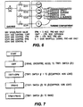
- FIGURE 6 shows the control system for use with gaseous fuel.
- Diffusion gas flow to the center nozzle is referred to as "1DIFF”.
- Premix gas flow to the center nozzle 33 is referred to as “1PM”
- premix gas flow to the outer nozzles 32 is referred to as "5PM”.
- a fourth gas fuel circuit which does not involve the endcover 30 or fuel nozzles 32, 33 is commonly used for control of combustion dynamics. This circuit is labeled "Q" for quaternary fuel.
- Q for quaternary fuel.
- a total of five gas fuel valves are used. The first of these is the Stop Speed Ratio Valve (SRV). This valve functions to provide a pre-determined reference pressure for the downstream Gas Control Valves which function to distribute gas fuel to the proper location.
- SRV Stop Speed Ratio Valve
- the unit is operated over the load range according to the sequence shown in FIGURE 7.
- the unit ignites, cross-fires, and accelerates to full speed-no load (FSNL) with diffusion fuel to the center diffusion nozzle 33. From this point, the unit continues to operate in diffusion mode up to a point designated as TTRF1 switch #1.
- the quantity TTRF1 refers to a combustion reference temperature used by the control system. This variable is often referred to as firing temperature.
- premix gaseous fuel is initiated to the outer 5 premix nozzles 32 for the purpose of reducing emissions of NOx and CO.
- the unit is loaded in this mode through a set point defined by TTRF1 switch #2. Here, gas fuel is discontinued through the center diffusion nozzle.
- An air purge of the center diffusion nozzle is initiated to provide cooling of the nozzle tip and prevent ingestion of combusting gases into the diffusion fuel nozzle.
- gaseous fuel is initiated to the premixed passage of the center nozzle.
- the unit is loaded to maximum power output in this mode. The unit down-loads by following the reverse path.
- Oil operation is less complex.
- the unit can ignite, cross-file and accelerate to FSNL on fuel oil. From FSNL, the unit is typically operated up to 50% load without diluent injection for emissions control. A flow of atomizing air is always required when operating on liquid fuel. As each of the liquid fuel, water injection, and atomizing air passages face the flame, each of these passages require an air purge when not in use.
- the above-described staging strategy eliminates the usual requirement for a diffusion gas passage in the outer (5PM) nozzles. Moreover, there is no need for liquid fuel flow in the center nozzle. This further eliminates the need for water injection and atomizing air to the center nozzle. As a result, the system and method of the invention does not require a piping system or valving for diffusion gas to the outer gas nozzles, nor does it require a piping system or valving for center liquid fuel, center water injection, or center atomizing air.
- the invention provides a compact means for configuring and operating an industrial gas turbine on gaseous and/or liquid fuels while utilizing fuel staging to achieve very low emissions on gaseous fuel.
Description
- The present invention relates to gas and liquid fueled turbines and, more particularly to methods of operating combustors having multiple nozzles for use in a turbine wherein the nozzles are staged between different modes of operation, and to the compact configuration that may be realized therewith.
- Dry Low NOx technology is routinely applied for emissions control with gaseous tuel combustion in industrial gas turbines with can-annular combustion systems through utilization of premixing of fuel and air. The primary benefit of premixing is to provide a uniform rate of combustion resulting in relatively constant reaction zone temperatures. Through careful air management, these temperatures can be optimized to produce very low emissions of oxides of nitrogen (NOx), carbon monoxide (CO), and unburned hydrocarbons (UHC). Modulation of a center premix fuel nozzle can expand the range of operation by allowing the fuel-air ratio and corresponding reaction rates of the outer nozzles to remain relatively constant while varying the fuel input into the machine. Detailed methods for controlling or operating such a machine on natural gas are described for example in Davis, Dry Low NOx Combustion Systems For GE Heavy-Duty Gas Turbines, GER-3568F, 1996 and in U.S. Patent Nos. 5,722,230 and 5,729,968.
- Liquid fuel is commonly supplied in industrial gas turbines with diluent injection for emissions control from approximately 50 to 100 percent of rated load. Water or steam is generally used as the diluent. Combustors with capability of operating on either gaseous or liquid fuels are well established and examples thereof are described in the aforementioned publications.
- US-A-5,836,164 comprises a gas turbine combustor with a plurality of premixing combustors arranged at an outer periphery of the combustors and a plurality of second premixing combustors also arranged along the outer combustor periphery. The first and second premixing combustors are arranged alternately along the outer combustor periphery.
- US-A-5,729,968 comprises a center burner in a multi-bumer combustor where at start up a number of nozzles in a nozzle array are supplied with a diffusion fuel from the diffusion manifold. Then at part speed, pre-mix fuel is supplied tc a number of the nozzles in the array, and then at full speed transferring the nozzles receiving diffusion fuel to a pre-mix fuel.
- The problems associated with dual fuel machines include the packaging requirements associated with locating a number of fluid passages within a limited volume and the development of an effective methodology to control the operation of the machine while meeting the ever-lower emissions levels required by environmental agencies throughout the world. Solving these problems is of particular difficulty for small industrial gas turbines with can-annular combustion systems with lower than 35 Megawatts power output.
- The nozzle configuration and control methodology of the invention is adapted to provide a compact means for configuring and operating an industrial gas turbine on either gaseous or liquid fuel while utilizing fuel staging to achieve very low emissions. More specifically, the invention is embodied in a configuration and operational methodology wherein the outer fuel nozzles are used for delivery of a portion of the premix gaseous fuel and all liquid fuel. Water injection for emissions control when operating on liquid fuel and atomizing air are also supplied entirely by the outer fuel nozzles. The central fuel nozzle is thus reserved for the supply of both premix gaseous fuel and diffusion gaseous fuel.
- Thus, the invention is embodied in a gas turbine in which a plurality of combustors are provided, each having a plurality of outer fuel nozzles, e.g. from three to six, arranged about a longitudinal axis of the combustor, a center nozzle disposed substantially along the longitudinal axis, and a single combustion zone. Each outer fuel nozzle has at least one premix gas passage connected to at least one premix gas inlet and communicating with a plurality of radially extending premix fuel injectors disposed within a dedicated premix tube adapted to mix premix fuel and combustion air prior to entry into the single combustion zone located downstream of the premix tube. The center nozzle also has at least one premix gas passage connected to at least one premix gas inlet and communicating with a plurality of radially extending premix fuel injectors disposed within a dedicated premix tube adapted to mix premix fuel and combustion air prior to entry into the single combustion zone located downstream of the premix tube. The center nozzle further has a diffusion gas passage connected to a diffusion gas inlet. The diffusion gas passage terminates at a forwardmost discharge end of the center fuel nozzle downstream of the premix fuel injectors but within the dedicated premix tube.
- The invention is further embodied in a method of operating a combustor wherein the combustor has a plurality of outer fuel nozzles in an annular array arranged about a center axis and a center nozzle located on the center axis, and wherein the annular array is selectively supplied with premix fuel, liquid fuel, water and atomizing air, and further wherein the center nozzle is selectively supplied with diffusion fuel and premix fuel, the method comprising the steps of:
- a) at start-up, supplying the center fuel nozzle with diffusion fuel;
- b) as the unit load is raised, supplying premix fuel to at least one of the outer nozzles in the annular array;
- c) at part load, ceasing diffusion fuel flow to the center nozzle;
- d) as load is further increased, initiating premix fuel supply to the center nozzle without adding to the supply of premix fuel to the outer fuel nozzles in the annular array; and then
- e) supplying additional premix fuel to all of the outer fuel nozzles in the annular array and to the center nozzle as the turbine load increases.
-
- These, as well as other objects and advantages of this invention, will be more completely understood and appreciated by careful study of the following more detailed description of the presently preferred exemplary embodiments of the invention taken in conjunction with the accompanying drawings, in which:
- FIGURE 1 is a schematic cross-sectional view through one of the combustors of a turbine in accordance with an exemplary embodiment of the invention;
- FIGURE 2 is a schematic front end view of an end cover and fuel nozzle assembly embodying the invention;
- FIGURE 3 is a schematic cross-sectional view of an end cover and fuel nozzle assembly taken along line 3-3 in FIGURE 2;
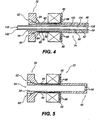
- FIGURE 4 is a schematic cross-sectional view of an outer fuel nozzle embodying the invention;
- FIGURE 5 is a schematic cross-sectional view of a center fuel nozzle embodying the invention;
- FIGURE 6 is a schematic illustration of a gas fuel control system embodying the invention; and
- FIGURE 7 is an illustration of the unit operation sequence of a presently preferred embodiment of the invention.
-
- Requirements for dual fuel capability can result in considerable complexity because of the number of flow passages required. Moreover, stringent emissions requirements for gas turbine power plants force utilization of Dry Low NOx, or DLN systems, for combustion of natural gas. These DLN systems typically supply fuel gas to three or more locations within the combustion system in order to meet specifications for emissions, load variation (turndown), metal hardware temperatures, and acceptable combustion acoustic dynamics.
- This invention provides a compact means for configuring and operating an industrial gas turbine on gaseous and/or liquid fuels while utilizing fuel staging to achieve very low emissions on gaseous fuel. The system comprising this invention is a part of one (each) combustor assembly arranged in a can-annular configuration on an industrial gas turbine. In gas turbines with can-annular combustor configurations, a series of combustion chambers or cans are located around the circumference of the machine and gas and liquid fuel nozzles are disposed in the combustion chambers to direct fuel to various locations therewithin. FIGURE 1 is a schematic cross-sectional view through one of the combustors of such a turbine, in which the system of the invention is advantageously incorporated.
- The
gas turbine 10 includes a compressor 12 (partially shown), a plurality of combustors 14 (one shown), and a turbine represented here by asingle blade 16. Although not specifically shown, the turbine is drivingly connected to the compressor 12 along a common axis. The compressor 12 pressurizes inlet air which is then reverse flowed to thecombustor 14 where it is used to cool the combustor and to provide air to the combustion process. - As noted above, the gas turbine includes a plurality of
combustors 14 located about the periphery of the gas turbine. A double-walled transition duct 18 connects the outlet end of each combustor with the inlet end of the turbine to deliver the hot products of combustion to the turbine. Ignition is achieved in thevarious combustors 14 by means ofspark plug 20 in conjunction with cross fire tubes 22 (one shown) in the usual manner. - Each
combustor 14 includes a substantiallycylindrical combustion casing 24 which is secured at an open forward end to theturbine casing 26 by means ofbolts 28. The rearward or proximal end of the combustion casing is closed by anend cover assembly 30 which includes supply tubes, manifolds and associated valves for feeding gaseous fuel, liquid fuel, air and water to the combustor as described in greater detail below. Theend cover assembly 30 receives a plurality (for example, three to six) "outer" fuel nozzle assemblies 32 (only one shown in FIGURE 1 for purposes of convenience and clarity), arranged in a circular array about a longitudinal axis of the combustor, and one center nozzle 33 (see FIGURE 2). - Within the
combustor casing 24, there is mounted, in substantially concentric relation thereto, a substantiallycylindrical flow sleeve 34 which connects at its forward end to theouter wall 36 of the doublewalled transition duct 18. Theflow sleeve 34 is connected at its rearward end by means of aradial flange 35 to thecombustor casing 24 at abutt joint 37 where fore and aft sections of thecombustor casing 24 are joined. - Within the
flow sleeve 34, there is a concentrically arrangedcombustion liner 38 which is connected at its forward end with theinner wall 40 of thetransition duct 18. The rearward end of thecombustion liner 38 is supported by a combustionliner cap assembly 42 which is, in turn, supported within the combustor casing by a plurality ofstruts 39 and an associated mounting assembly (not shown in detail).Outer wall 36 of thetransition duct 18 and that portion offlow sleeve 34 extending forward of the location where thecombustion casing 24 is bolted to the turbine casing (by bolts 28) are formed with an array ofapertures 44 over their respective peripheral surfaces to permit air to reverse flow from the compressor 12 through theapertures 44 into the annular space between theflow sleeve 34 and theliner 38 toward the upstream or rearward end of the combustor (as indicated by the flow arrows shown in FIGURE 1). - The combustion
liner cap assembly 42 supports a plurality ofpremix tubes 46, one for eachfuel nozzle assembly premix tube 46 is supported within the combustionliner cap assembly 42 at its forward and rearward ends by front andrear plates ended premix tubes 46. The front plate 47 (an impingement plate provided with an array of cooling apertures) may be shielded from the thermal radiation of the combustor flame by shield plates (not shown). - The
rear plate 49 mounts a plurality of rearwardly extending floating collars 48 (one for eachpremix tube 46, arranged in substantial alignment with the openings in the rear plate), each of which supports anair swirler 50 in surrounding relation to a radially outermost wall of the respective nozzle assembly. The arrangement is such that air flowing in the annular space between theliner 38 andflow sleeve 34 is forced to again reverse direction in the rearward end of the combustor (between theend cap assembly 30 and sleeve cap assembly 44) and to flow through theswirlers 50 andpremix tubes 46 before entering the burning orcombustion zone 70 within theliner 38, downstream of thepremix tubes 46. The construction details of the combustionliner cap assembly 42, the manner in which the liner cap assembly is supported within the combustion casing, and the manner in which thepremix tubes 46 are supported in the liner cap assembly in the subject of U.S. Patent No. 5,259,184. - As noted above, the system comprising this invention is a part of one (each) combustor assembly arranged in a can-annular configuration on an industrial gas turbine. The system provides
outer fuel nozzles 32 and acenter fuel nozzle 33, all attached toendcover 30. Theendcover 30 contains internal passages which supply the gaseous and liquid fuel, water, and atomizing air to the nozzles as detailed below. Piping and tubing for supply of the various fluids are in turn connected to the outer surface of the endcover assembly. FIGURES 2 and 3 schematically show the proposed endcover arrangement wherein the outer nozzles supply both premix gaseous fuel and liquid fuel, as well as water injection and atomizing air, and thecenter nozzle 33 is adapted to supply diffusion gaseous fuel centrally and premix gaseous fuel radially. - More specifically, the gas nozzles are configured in a manner so as to provide from 4 to 6 radially
outer nozzles 32 and onecenter nozzle 33. In the present preferred embodiment of the invention, the outer nozzles and the center gas nozzle all provide premix gaseous fuel. Thecenter nozzle 33, only, provides gaseous diffusion fuel. Thus, referring to FIGURES 2, 3 and 5, the centerfuel nozzle assembly 33 includes a proximal end orrearward supply section 52 with adiffusion gas inlet 54 for receiving diffusion gas fuel into arespective passage 56 that extends through the center nozzle assembly. The central passage supplies diffusion gas to the burningzone 70 of the combustor viaorifices 58 defined at theforwardmost end 60 of the centerfuel nozzle assembly 33. In use, the distal end or forward discharge end 60 of the center nozzle is located within thepremix tube 46 but relatively close to the distal or forward end thereof. - Inlet(s) 62 are also defined in the
proximal end 52 of the nozzle for premix gas fuel. The premix gas passage(s) 64 communicate with a plurality ofradial fuel injectors 66, each of which is provided with a plurality of fuel injection ports or holes 68 for discharging premix gas fuel into a premix zone located within thepremix tube 46. - Referring to FIGURES 2, 3 and 4, each outer
fuel nozzle assembly 32 includes a proximal end orrearward supply section 72, with inlets for receiving liquid fuel, water injection, atomizing air, and premix gas fuel, and with suitable connecting passages for supplying each of the above-mentioned fluids to a respective passage in a forward ordistal delivery section 74 of the fuel nozzle assembly. - In the illustrated embodiment, the forward delivery section of the outer fuel nozzle assembly is comprised of a series of concentric tubes.
Tubes rearward supply section 72 viaconduit 84. Thepremix gas passages 80 communicate with a plurality ofradial fuel injectors 86 each of which is provided with a plurality of fuel injection ports or holes 88 for discharging gas fuel into the premix zone located within thepremix tube 46. As described above with reference to thecenter nozzle 33, the injected premix fuel mixes with air reverse flowed from the compressor. - A
second passage 90 is defined betweenconcentric tubes air inlet 94 to the burningzone 70 of the combustor viaorifice 96. Athird passage 98 is defined betweenconcentric tubes water inlet 102 to the burningzone 70 to effect NOx reductions in the manner understood by those skilled in the art. -
Tube 100, the innermost of the series of concentric tubes forming theouter nozzle 32, itself forms acentral passage 104 for liquid fuel which enters the passage vialiquid fuel inlet 106. The liquid fuel exits the nozzle by means of adischarge orifice 108 in the center of thenozzle assembly 32. Thus, all outer and the center gas nozzles provide premix gaseous fuel. The center nozzle, but not the outer nozzles, provides gaseous diffusion fuel, and each of the outer nozzles, but not the center nozzle, is configured for delivering liquid fuel, water for emissions abatement, and atomizing air. - In the presently preferred embodiment of the invention, the machine operates on gaseous fuel in a number of modes. The first mode supplies diffusion gaseous fuel to the
center nozzle 33, only, for acceleration of the machine and very low load operation. As the unit load is further raised, premix gaseous fuel is supplied to theouter gas nozzles 32. At approximately 40% load, thecenter nozzle 33 diffusion fuel is turned off and that percentage of the fuel is redirected to the outer gas nozzles. From 40 to 50% load, fuel is supplied exclusively to the outer premixed and quaternay nozzles. At approximately 50% load, thecenter nozzle 33 is turned on again to deliver premix gaseous fuel through the premix gas fuel passage(s) 64. This mode is applied with controlled fuel percentages to the premix gas nozzles up to 100% of the rated load. Actual percentages of fuel flow to the premixed nozzles are modulated to optimize emissions, dynamics, and flame stability. Liquid fuel is supplied through the outer fuel nozzles across the entire range of operation. Atomizing air is always required when operating on liquid fuel. Water injection for emissions abatement is required when operating on liquid fuel from approximately 50% up to full load. - FIGURE 6 shows the control system for use with gaseous fuel. Diffusion gas flow to the center nozzle is referred to as "1DIFF". Premix gas flow to the
center nozzle 33 is referred to as "1PM", and premix gas flow to theouter nozzles 32 is referred to as "5PM". A fourth gas fuel circuit which does not involve theendcover 30 orfuel nozzles - The unit is operated over the load range according to the sequence shown in FIGURE 7. The unit ignites, cross-fires, and accelerates to full speed-no load (FSNL) with diffusion fuel to the
center diffusion nozzle 33. From this point, the unit continues to operate in diffusion mode up to a point designated asTTRF1 switch # 1. The quantity TTRF1 refers to a combustion reference temperature used by the control system. This variable is often referred to as firing temperature. At the switch point, premix gaseous fuel is initiated to the outer 5premix nozzles 32 for the purpose of reducing emissions of NOx and CO. The unit is loaded in this mode through a set point defined byTTRF1 switch # 2. Here, gas fuel is discontinued through the center diffusion nozzle. An air purge of the center diffusion nozzle is initiated to provide cooling of the nozzle tip and prevent ingestion of combusting gases into the diffusion fuel nozzle. At a point defined byTTRF1 switch # 3, gaseous fuel is initiated to the premixed passage of the center nozzle. The unit is loaded to maximum power output in this mode. The unit down-loads by following the reverse path. - Oil operation is less complex. The unit can ignite, cross-file and accelerate to FSNL on fuel oil. From FSNL, the unit is typically operated up to 50% load without diluent injection for emissions control. A flow of atomizing air is always required when operating on liquid fuel. As each of the liquid fuel, water injection, and atomizing air passages face the flame, each of these passages require an air purge when not in use.
- The above-described staging strategy eliminates the usual requirement for a diffusion gas passage in the outer (5PM) nozzles. Moreover, there is no need for liquid fuel flow in the center nozzle. This further eliminates the need for water injection and atomizing air to the center nozzle. As a result, the system and method of the invention does not require a piping system or valving for diffusion gas to the outer gas nozzles, nor does it require a piping system or valving for center liquid fuel, center water injection, or center atomizing air.
- As will be appreciated from the foregoing description, the invention provides a compact means for configuring and operating an industrial gas turbine on gaseous and/or liquid fuels while utilizing fuel staging to achieve very low emissions on gaseous fuel.
Claims (2)
- A method of operating a combustor (14) wherein the combustor has a plurality of outer fuel nozzles (32) in an annular array arranged about a center axis and a center nozzle (33) located on the center axis, and wherein the annular array is selectively supplied with premix gas fuel (82), liquid fuel (106), water (102) and atomizing air (94), and further wherein the center nozzle is selectively supplied with diffusion gas fuel (54) and premix gas fuel (62), the method comprising the steps of:a) at start-up, supplying the center fuel nozzle (33) with diffusion gas fuel (54);b) as the unit load is raised, supplying premix gas fuel (82) to at least one of the outer nozzles (32) in the annular array;c) at part load, ceasing diffusion gas fuel (54) flow to the center nozzle (33) and redirecting a corresponding percentage of fuel to at least one of the outer nozzles (32) in the annular array, thereby to maintain fuel flow constant;d) after load is further increased, initiating premix gas fuel (62) supply to the center nozzle (33) without adding to the supply of premix gas fuel to the outer fuel nozzles in the annular array: and thene) selectively additional premix gas fuel (62, 82) to all of the fuel nozzles (32) in the annular array and to the center nozzle (33) as the turbine load increases.
- The method of claim 1, wherein each fuel nozzle in the annular array of outer nozzles (32) includes an air swirler (50) for swirling air passing through the combustor (14), and wherein, during steps b), d), and e), premix gas fuel is supplied to the annular array of outer nozzles (32) at locations (82) upstream of said air swirlers (50) and discharged (86, 88) from said outer nozzles (32) downstream of said air swirlers (50).
Applications Claiming Priority (2)
| Application Number | Priority Date | Filing Date | Title |
|---|---|---|---|
| US09/456,864 US6598383B1 (en) | 1999-12-08 | 1999-12-08 | Fuel system configuration and method for staging fuel for gas turbines utilizing both gaseous and liquid fuels |
| US456864 | 1999-12-08 |
Publications (2)
| Publication Number | Publication Date |
|---|---|
| EP1106928A1 EP1106928A1 (en) | 2001-06-13 |
| EP1106928B1 true EP1106928B1 (en) | 2005-09-07 |
Family
ID=23814441
Family Applications (1)
| Application Number | Title | Priority Date | Filing Date |
|---|---|---|---|
| EP00310915A Expired - Lifetime EP1106928B1 (en) | 1999-12-08 | 2000-12-08 | Method for staging fuel for gas turbines utilizing both gaseous and liquid fuels |
Country Status (4)
| Country | Link |
|---|---|
| US (2) | US6598383B1 (en) |
| EP (1) | EP1106928B1 (en) |
| JP (1) | JP4681113B2 (en) |
| DE (1) | DE60022457T2 (en) |
Families Citing this family (110)
| Publication number | Priority date | Publication date | Assignee | Title |
|---|---|---|---|---|
| DK1155225T3 (en) * | 1999-02-24 | 2003-11-17 | Kema Nv | Combustion unit for combustion of a liquid fuel and a power generation system comprising such combustion unit |
| DE10049203A1 (en) * | 2000-10-05 | 2002-05-23 | Alstom Switzerland Ltd | Process for introducing fuel into a premix burner |
| US6915636B2 (en) * | 2002-07-15 | 2005-07-12 | Power Systems Mfg., Llc | Dual fuel fin mixer secondary fuel nozzle |
| US6786046B2 (en) * | 2002-09-11 | 2004-09-07 | Siemens Westinghouse Power Corporation | Dual-mode nozzle assembly with passive tip cooling |
| US6962055B2 (en) * | 2002-09-27 | 2005-11-08 | United Technologies Corporation | Multi-point staging strategy for low emission and stable combustion |
| GB2404729B (en) * | 2003-08-08 | 2008-01-23 | Rolls Royce Plc | Fuel injection |
| US7284378B2 (en) * | 2004-06-04 | 2007-10-23 | General Electric Company | Methods and apparatus for low emission gas turbine energy generation |
| US7093444B2 (en) * | 2003-12-20 | 2006-08-22 | Yeungnam Educational Foundation | Simultaneous combustion with premixed and non-premixed fuels and fuel injector for such combustion |
| US20050144930A1 (en) * | 2004-01-05 | 2005-07-07 | Shu-Heng Sun | Gas explosion machine |
| US7010461B2 (en) * | 2004-02-09 | 2006-03-07 | General Electric Company | Method and system for real time reporting of boiler adjustment using emission sensor data mapping |
| US7104070B2 (en) * | 2004-03-04 | 2006-09-12 | General Electric Company | Liquid fuel nozzle apparatus with passive water injection purge |
| US7185494B2 (en) * | 2004-04-12 | 2007-03-06 | General Electric Company | Reduced center burner in multi-burner combustor and method for operating the combustor |
| US7546740B2 (en) * | 2004-05-11 | 2009-06-16 | United Technologies Corporation | Nozzle |
| US7350357B2 (en) * | 2004-05-11 | 2008-04-01 | United Technologies Corporation | Nozzle |
| US7137258B2 (en) * | 2004-06-03 | 2006-11-21 | General Electric Company | Swirler configurations for combustor nozzles and related method |
| US7007477B2 (en) * | 2004-06-03 | 2006-03-07 | General Electric Company | Premixing burner with impingement cooled centerbody and method of cooling centerbody |
| US7082765B2 (en) * | 2004-09-01 | 2006-08-01 | General Electric Company | Methods and apparatus for reducing gas turbine engine emissions |
| US7546735B2 (en) * | 2004-10-14 | 2009-06-16 | General Electric Company | Low-cost dual-fuel combustor and related method |
| JP4015656B2 (en) * | 2004-11-17 | 2007-11-28 | 三菱重工業株式会社 | Gas turbine combustor |
| US7269939B2 (en) * | 2004-11-24 | 2007-09-18 | General Electric Company | Method and apparatus for automatically actuating fuel trim valves in a gas |
| EP1712837A1 (en) * | 2005-04-14 | 2006-10-18 | Siemens Aktiengesellschaft | Burner assembly and method of operating it |
| JP4728176B2 (en) * | 2005-06-24 | 2011-07-20 | 株式会社日立製作所 | Burner, gas turbine combustor and burner cooling method |
| US7661327B2 (en) * | 2005-07-12 | 2010-02-16 | John Frank Bourgein | Method and system for dynamic sensing, presentation and control of combustion boiler conditions |
| US7854121B2 (en) * | 2005-12-12 | 2010-12-21 | General Electric Company | Independent pilot fuel control in secondary fuel nozzle |
| US8075305B2 (en) | 2006-01-24 | 2011-12-13 | Exxonmobil Chemical Patents Inc. | Dual fuel gas-liquid burner |
| US7901204B2 (en) * | 2006-01-24 | 2011-03-08 | Exxonmobil Chemical Patents Inc. | Dual fuel gas-liquid burner |
| US7909601B2 (en) * | 2006-01-24 | 2011-03-22 | Exxonmobil Chemical Patents Inc. | Dual fuel gas-liquid burner |
| US7549293B2 (en) * | 2006-02-15 | 2009-06-23 | General Electric Company | Pressure control method to reduce gas turbine fuel supply pressure requirements |
| US8308477B2 (en) | 2006-03-01 | 2012-11-13 | Honeywell International Inc. | Industrial burner |
| US20070234735A1 (en) * | 2006-03-28 | 2007-10-11 | Mosbacher David M | Fuel-flexible combustion sytem and method of operation |
| GB2446164A (en) * | 2007-02-05 | 2008-08-06 | Ntnu Technology Transfer As | Gas Turbine Emissions Reduction with Premixed and Diffusion Combustion |
| US7966820B2 (en) * | 2007-08-15 | 2011-06-28 | General Electric Company | Method and apparatus for combusting fuel within a gas turbine engine |
| US7891192B2 (en) * | 2007-08-28 | 2011-02-22 | General Electric Company | Gas turbine engine combustor assembly having integrated control valves |
| JP4764392B2 (en) * | 2007-08-29 | 2011-08-31 | 三菱重工業株式会社 | Gas turbine combustor |
| US8122725B2 (en) * | 2007-11-01 | 2012-02-28 | General Electric Company | Methods and systems for operating gas turbine engines |
| US8528337B2 (en) * | 2008-01-22 | 2013-09-10 | General Electric Company | Lobe nozzles for fuel and air injection |
| US7908863B2 (en) * | 2008-02-12 | 2011-03-22 | General Electric Company | Fuel nozzle for a gas turbine engine and method for fabricating the same |
| US9062563B2 (en) * | 2008-04-09 | 2015-06-23 | General Electric Company | Surface treatments for preventing hydrocarbon thermal degradation deposits on articles |
| EP2161500A1 (en) * | 2008-09-04 | 2010-03-10 | Siemens Aktiengesellschaft | Combustor system and method of reducing combustion instability and/or emissions of a combustor system |
| US7895821B2 (en) * | 2008-12-31 | 2011-03-01 | General Electric Company | System and method for automatic fuel blending and control for combustion gas turbine |
| US8381529B2 (en) * | 2009-01-29 | 2013-02-26 | General Electric Company | System and method for water injection in a turbine engine |
| US20100192582A1 (en) * | 2009-02-04 | 2010-08-05 | Robert Bland | Combustor nozzle |
| US8347631B2 (en) * | 2009-03-03 | 2013-01-08 | General Electric Company | Fuel nozzle liquid cartridge including a fuel insert |
| US20100242490A1 (en) * | 2009-03-31 | 2010-09-30 | General Electric Company | Additive delivery systems and methods |
| US8763399B2 (en) * | 2009-04-03 | 2014-07-01 | Hitachi, Ltd. | Combustor having modified spacing of air blowholes in an air blowhole plate |
| JP5476462B2 (en) * | 2009-05-07 | 2014-04-23 | ゼネラル・エレクトリック・カンパニイ | Multi premixer fuel nozzle |
| US8437941B2 (en) | 2009-05-08 | 2013-05-07 | Gas Turbine Efficiency Sweden Ab | Automated tuning of gas turbine combustion systems |
| US9671797B2 (en) | 2009-05-08 | 2017-06-06 | Gas Turbine Efficiency Sweden Ab | Optimization of gas turbine combustion systems low load performance on simple cycle and heat recovery steam generator applications |
| US9354618B2 (en) | 2009-05-08 | 2016-05-31 | Gas Turbine Efficiency Sweden Ab | Automated tuning of multiple fuel gas turbine combustion systems |
| US9267443B2 (en) | 2009-05-08 | 2016-02-23 | Gas Turbine Efficiency Sweden Ab | Automated tuning of gas turbine combustion systems |
| US8616002B2 (en) * | 2009-07-23 | 2013-12-31 | General Electric Company | Gas turbine premixing systems |
| US8196408B2 (en) * | 2009-10-09 | 2012-06-12 | General Electric Company | System and method for distributing fuel in a turbomachine |
| US8584467B2 (en) * | 2010-02-12 | 2013-11-19 | General Electric Company | Method of controlling a combustor for a gas turbine |
| US8468834B2 (en) * | 2010-02-12 | 2013-06-25 | General Electric Company | Fuel injector nozzle |
| US8555648B2 (en) * | 2010-02-12 | 2013-10-15 | General Electric Company | Fuel injector nozzle |
| RU2534189C2 (en) * | 2010-02-16 | 2014-11-27 | Дженерал Электрик Компани | Gas turbine combustion chamber (versions) and method of its operation |
| EP2362141A1 (en) * | 2010-02-19 | 2011-08-31 | Siemens Aktiengesellschaft | Burner assembly |
| DE102010009051A1 (en) | 2010-02-23 | 2011-08-25 | Deutsches Zentrum für Luft- und Raumfahrt e.V., 51147 | Fuel supply device for use in gas turbine combustion chamber system for technical combustion chamber system for flame less combustion, has main nozzle with fuel supply and another nozzle for supplying fuel |
| US8438852B2 (en) * | 2010-04-06 | 2013-05-14 | General Electric Company | Annular ring-manifold quaternary fuel distributor |
| US8418468B2 (en) | 2010-04-06 | 2013-04-16 | General Electric Company | Segmented annular ring-manifold quaternary fuel distributor |
| US8627668B2 (en) * | 2010-05-25 | 2014-01-14 | General Electric Company | System for fuel and diluent control |
| US9557050B2 (en) | 2010-07-30 | 2017-01-31 | General Electric Company | Fuel nozzle and assembly and gas turbine comprising the same |
| US8613197B2 (en) * | 2010-08-05 | 2013-12-24 | General Electric Company | Turbine combustor with fuel nozzles having inner and outer fuel circuits |
| US20120048961A1 (en) * | 2010-08-31 | 2012-03-01 | General Electric Company | Dual soft passage nozzle |
| US8733106B2 (en) * | 2011-05-03 | 2014-05-27 | General Electric Company | Fuel injector and support plate |
| US8919125B2 (en) | 2011-07-06 | 2014-12-30 | General Electric Company | Apparatus and systems relating to fuel injectors and fuel passages in gas turbine engines |
| EP2551470A1 (en) * | 2011-07-26 | 2013-01-30 | Siemens Aktiengesellschaft | Method for starting a stationary gas turbine |
| US9243804B2 (en) | 2011-10-24 | 2016-01-26 | General Electric Company | System for turbine combustor fuel mixing |
| US9267433B2 (en) | 2011-10-24 | 2016-02-23 | General Electric Company | System and method for turbine combustor fuel assembly |
| US9188061B2 (en) | 2011-10-24 | 2015-11-17 | General Electric Company | System for turbine combustor fuel assembly |
| US8973366B2 (en) | 2011-10-24 | 2015-03-10 | General Electric Company | Integrated fuel and water mixing assembly for use in conjunction with a combustor |
| US8894407B2 (en) * | 2011-11-11 | 2014-11-25 | General Electric Company | Combustor and method for supplying fuel to a combustor |
| US9366440B2 (en) | 2012-01-04 | 2016-06-14 | General Electric Company | Fuel nozzles with mixing tubes surrounding a liquid fuel cartridge for injecting fuel in a gas turbine combustor |
| JP5458121B2 (en) * | 2012-01-27 | 2014-04-02 | 株式会社日立製作所 | Gas turbine combustor and method of operating gas turbine combustor |
| US8511086B1 (en) * | 2012-03-01 | 2013-08-20 | General Electric Company | System and method for reducing combustion dynamics in a combustor |
| US9003806B2 (en) | 2012-03-05 | 2015-04-14 | General Electric Company | Method of operating a combustor from a liquid fuel to a gas fuel operation |
| US9163839B2 (en) * | 2012-03-19 | 2015-10-20 | General Electric Company | Micromixer combustion head end assembly |
| US9103284B2 (en) * | 2012-05-31 | 2015-08-11 | General Electric Company | Utilization of fuel gas for purging a dormant fuel gas circuit |
| US20140096526A1 (en) * | 2012-10-08 | 2014-04-10 | General Electric Company | System for operating a combustor of a gas turbine |
| US9383098B2 (en) | 2012-10-31 | 2016-07-05 | General Electric Company | Radial flow fuel nozzle for a combustor of a gas turbine |
| US10100741B2 (en) * | 2012-11-02 | 2018-10-16 | General Electric Company | System and method for diffusion combustion with oxidant-diluent mixing in a stoichiometric exhaust gas recirculation gas turbine system |
| US9677766B2 (en) * | 2012-11-28 | 2017-06-13 | General Electric Company | Fuel nozzle for use in a turbine engine and method of assembly |
| US9151503B2 (en) * | 2013-01-04 | 2015-10-06 | General Electric Company | Coaxial fuel supply for a micromixer |
| JP6190670B2 (en) * | 2013-08-30 | 2017-08-30 | 三菱日立パワーシステムズ株式会社 | Gas turbine combustion system |
| US9476592B2 (en) | 2013-09-19 | 2016-10-25 | General Electric Company | System for injecting fuel in a gas turbine combustor |
| JP6210810B2 (en) * | 2013-09-20 | 2017-10-11 | 三菱日立パワーシステムズ株式会社 | Dual fuel fired gas turbine combustor |
| US10125695B2 (en) | 2013-10-04 | 2018-11-13 | United Technologies Corporation | Automatic control of turbine blade temperature during gas turbine engine operation |
| ITMI20131816A1 (en) * | 2013-10-31 | 2015-05-01 | Ansaldo Energia Spa | INJECTOR WITH A DOUBLE NOZZLE SPEAR GAS TURBINE SYSTEM, GAS TURBINE SYSTEM AND A GAS TURBINE FEEDING METHOD |
| DE112015003097T5 (en) | 2014-07-02 | 2017-03-30 | Nuovo Pignone Srl | Brennstoffverteileinrichtung, gas turbine and assembly process |
| JP6325930B2 (en) * | 2014-07-24 | 2018-05-16 | 三菱日立パワーシステムズ株式会社 | Gas turbine combustor |
| US20160061108A1 (en) * | 2014-08-27 | 2016-03-03 | Siemens Energy, Inc. | Diffusion flame burner for a gas turbine engine |
| JP6516996B2 (en) * | 2014-10-10 | 2019-05-22 | 川崎重工業株式会社 | Combustor and gas turbine engine |
| US11428413B2 (en) * | 2016-03-25 | 2022-08-30 | General Electric Company | Fuel injection module for segmented annular combustion system |
| US10634358B2 (en) | 2017-06-16 | 2020-04-28 | General Electric Company | System and method for igniting liquid fuel in a gas turbine combustor |
| US10655858B2 (en) | 2017-06-16 | 2020-05-19 | General Electric Company | Cooling of liquid fuel cartridge in gas turbine combustor head end |
| US10982593B2 (en) | 2017-06-16 | 2021-04-20 | General Electric Company | System and method for combusting liquid fuel in a gas turbine combustor with staged combustion |
| US10578306B2 (en) | 2017-06-16 | 2020-03-03 | General Electric Company | Liquid fuel cartridge unit for gas turbine combustor and method of assembly |
| US10663171B2 (en) * | 2017-06-19 | 2020-05-26 | General Electric Company | Dual-fuel fuel nozzle with gas and liquid fuel capability |
| KR102046457B1 (en) * | 2017-11-09 | 2019-11-19 | 두산중공업 주식회사 | Combustor and gas turbine including the same |
| US11619388B2 (en) | 2017-12-21 | 2023-04-04 | Collins Engine Nozzles, Inc. | Dual fuel gas turbine engine pilot nozzles |
| CA3142100A1 (en) * | 2019-05-30 | 2020-12-03 | Siemens Energy Global GmbH & Co. KG | Gas turbine water injection for emissions reduction |
| US11326521B2 (en) | 2020-06-30 | 2022-05-10 | General Electric Company | Methods of igniting liquid fuel in a turbomachine |
| US11614233B2 (en) | 2020-08-31 | 2023-03-28 | General Electric Company | Impingement panel support structure and method of manufacture |
| US11460191B2 (en) | 2020-08-31 | 2022-10-04 | General Electric Company | Cooling insert for a turbomachine |
| US11371702B2 (en) | 2020-08-31 | 2022-06-28 | General Electric Company | Impingement panel for a turbomachine |
| US11255545B1 (en) | 2020-10-26 | 2022-02-22 | General Electric Company | Integrated combustion nozzle having a unified head end |
| US20230266004A1 (en) * | 2022-02-22 | 2023-08-24 | Honeywell International Inc. | Ultra-low nox multi-port air staged burner apparatus |
| WO2023188749A1 (en) * | 2022-03-30 | 2023-10-05 | 三菱パワー株式会社 | Combustor and gas turbine |
| US11767766B1 (en) | 2022-07-29 | 2023-09-26 | General Electric Company | Turbomachine airfoil having impingement cooling passages |
| CN115451433B (en) * | 2022-09-22 | 2024-04-02 | 中国联合重型燃气轮机技术有限公司 | Fuel nozzle premixing system for combustion chamber of gas turbine |
Family Cites Families (20)
| Publication number | Priority date | Publication date | Assignee | Title |
|---|---|---|---|---|
| US4292801A (en) * | 1979-07-11 | 1981-10-06 | General Electric Company | Dual stage-dual mode low nox combustor |
| JPH01114623A (en) * | 1987-10-27 | 1989-05-08 | Toshiba Corp | Gas turbine combustor |
| JP2544470B2 (en) * | 1989-02-03 | 1996-10-16 | 株式会社日立製作所 | Gas turbine combustor and operating method thereof |
| US5259184A (en) | 1992-03-30 | 1993-11-09 | General Electric Company | Dry low NOx single stage dual mode combustor construction for a gas turbine |
| US5575153A (en) * | 1993-04-07 | 1996-11-19 | Hitachi, Ltd. | Stabilizer for gas turbine combustors and gas turbine combustor equipped with the stabilizer |
| US5359847B1 (en) * | 1993-06-01 | 1996-04-09 | Westinghouse Electric Corp | Dual fuel ultra-flow nox combustor |
| JPH0814565A (en) * | 1994-04-28 | 1996-01-19 | Hitachi Ltd | Gas turbine combustor |
| DE69515931T2 (en) * | 1994-06-10 | 2000-11-02 | Gen Electric | Regulation of a gas turbine combustion chamber |
| US5491970A (en) | 1994-06-10 | 1996-02-20 | General Electric Co. | Method for staging fuel in a turbine between diffusion and premixed operations |
| JP3183053B2 (en) | 1994-07-20 | 2001-07-03 | 株式会社日立製作所 | Gas turbine combustor and gas turbine |
| US5836164A (en) | 1995-01-30 | 1998-11-17 | Hitachi, Ltd. | Gas turbine combustor |
| JP2989515B2 (en) * | 1995-04-11 | 1999-12-13 | 三菱重工業株式会社 | Fuel nozzle for pilot burner in premixing type combustion |
| US5640841A (en) * | 1995-05-08 | 1997-06-24 | Crosby; Rulon | Plasma torch ignition for low NOx combustion turbine combustor with monitoring means and plasma generation control means |
| US5722230A (en) | 1995-08-08 | 1998-03-03 | General Electric Co. | Center burner in a multi-burner combustor |
| JPH09144562A (en) * | 1995-11-24 | 1997-06-03 | Toshiba Corp | Device and method for supplying fuel to gas turbine |
| JP3578852B2 (en) * | 1995-12-05 | 2004-10-20 | 東京瓦斯株式会社 | Fuel supply system for multi-burner type combustor and gas turbine having the fuel supply system |
| JPH1130422A (en) * | 1997-07-09 | 1999-02-02 | Ishikawajima Harima Heavy Ind Co Ltd | Low nox combustor for two-fluid cycle |
| US5987875A (en) * | 1997-07-14 | 1999-11-23 | Siemens Westinghouse Power Corporation | Pilot nozzle steam injection for reduced NOx emissions, and method |
| JPH11237049A (en) * | 1998-02-19 | 1999-08-31 | Ishikawajima Harima Heavy Ind Co Ltd | Nox combustor for gas turbine |
| US6145294A (en) * | 1998-04-09 | 2000-11-14 | General Electric Co. | Liquid fuel and water injection purge system for a gas turbine |
-
1999
- 1999-12-08 US US09/456,864 patent/US6598383B1/en not_active Expired - Lifetime
-
2000
- 2000-12-08 JP JP2000373657A patent/JP4681113B2/en not_active Expired - Fee Related
- 2000-12-08 DE DE60022457T patent/DE60022457T2/en not_active Expired - Lifetime
- 2000-12-08 EP EP00310915A patent/EP1106928B1/en not_active Expired - Lifetime
-
2001
- 2001-01-10 US US09/756,759 patent/US6397602B2/en not_active Expired - Lifetime
Also Published As
| Publication number | Publication date |
|---|---|
| DE60022457T2 (en) | 2006-06-29 |
| JP2001227745A (en) | 2001-08-24 |
| JP4681113B2 (en) | 2011-05-11 |
| US20010004827A1 (en) | 2001-06-28 |
| EP1106928A1 (en) | 2001-06-13 |
| DE60022457D1 (en) | 2005-10-13 |
| US6598383B1 (en) | 2003-07-29 |
| US6397602B2 (en) | 2002-06-04 |
Similar Documents
| Publication | Publication Date | Title |
|---|---|---|
| EP1106928B1 (en) | Method for staging fuel for gas turbines utilizing both gaseous and liquid fuels | |
| US7181916B2 (en) | Method for operating a reduced center burner in multi-burner combustor | |
| US5729968A (en) | Center burner in a multi-burner combustor | |
| JP3703879B2 (en) | Method for operating a combustor for a gas turbine | |
| JP5400936B2 (en) | Method and apparatus for burning fuel in a gas turbine engine | |
| US8959921B2 (en) | Flame tolerant secondary fuel nozzle | |
| JP3477274B2 (en) | Method of operating a combustor for a gas turbine | |
| CA2103433C (en) | Tertiary fuel injection system for use in a dry low nox combustion system | |
| US5685139A (en) | Diffusion-premix nozzle for a gas turbine combustor and related method | |
| EP0667492B1 (en) | Fuel nozzle | |
| EP2216600B1 (en) | Combustor nozzle | |
| EP0564184B1 (en) | Single stage dual mode combustor | |
| US6374615B1 (en) | Low cost, low emissions natural gas combustor | |
| KR20050029676A (en) | Method and apparatus for reducing gas turbine engine emissions | |
| US9557050B2 (en) | Fuel nozzle and assembly and gas turbine comprising the same | |
| US10739007B2 (en) | Flamesheet diffusion cartridge |
Legal Events
| Date | Code | Title | Description |
|---|---|---|---|
| PUAI | Public reference made under article 153(3) epc to a published international application that has entered the european phase |
Free format text: ORIGINAL CODE: 0009012 |
|
| AK | Designated contracting states |
Kind code of ref document: A1 Designated state(s): CH DE FR GB IT LI |
|
| AX | Request for extension of the european patent |
Free format text: AL;LT;LV;MK;RO;SI |
|
| 17P | Request for examination filed |
Effective date: 20011213 |
|
| AKX | Designation fees paid |
Free format text: CH DE FR GB IT LI |
|
| 17Q | First examination report despatched |
Effective date: 20040729 |
|
| GRAP | Despatch of communication of intention to grant a patent |
Free format text: ORIGINAL CODE: EPIDOSNIGR1 |
|
| RTI1 | Title (correction) |
Free format text: METHOD FOR STAGING FUEL FOR GAS TURBINES UTILIZING BOTH GASEOUS AND LIQUID FUELS |
|
| GRAS | Grant fee paid |
Free format text: ORIGINAL CODE: EPIDOSNIGR3 |
|
| GRAA | (expected) grant |
Free format text: ORIGINAL CODE: 0009210 |
|
| AK | Designated contracting states |
Kind code of ref document: B1 Designated state(s): CH DE FR GB IT LI |
|
| REG | Reference to a national code |
Ref country code: GB Ref legal event code: FG4D |
|
| REG | Reference to a national code |
Ref country code: CH Ref legal event code: EP Ref country code: CH Ref legal event code: NV Representative=s name: SERVOPATENT GMBH |
|
| REF | Corresponds to: |
Ref document number: 60022457 Country of ref document: DE Date of ref document: 20051013 Kind code of ref document: P |
|
| ET | Fr: translation filed | ||
| PLBE | No opposition filed within time limit |
Free format text: ORIGINAL CODE: 0009261 |
|
| STAA | Information on the status of an ep patent application or granted ep patent |
Free format text: STATUS: NO OPPOSITION FILED WITHIN TIME LIMIT |
|
| 26N | No opposition filed |
Effective date: 20060608 |
|
| REG | Reference to a national code |
Ref country code: CH Ref legal event code: PFA Owner name: GENERAL ELECTRIC COMPANY Free format text: GENERAL ELECTRIC COMPANY#1 RIVER ROAD#SCHENECTADY, NY 12345 (US) -TRANSFER TO- GENERAL ELECTRIC COMPANY#1 RIVER ROAD#SCHENECTADY, NY 12345 (US) |
|
| PGFP | Annual fee paid to national office [announced via postgrant information from national office to epo] |
Ref country code: GB Payment date: 20131227 Year of fee payment: 14 |
|
| GBPC | Gb: european patent ceased through non-payment of renewal fee |
Effective date: 20141208 |
|
| PG25 | Lapsed in a contracting state [announced via postgrant information from national office to epo] |
Ref country code: GB Free format text: LAPSE BECAUSE OF NON-PAYMENT OF DUE FEES Effective date: 20141208 |
|
| REG | Reference to a national code |
Ref country code: FR Ref legal event code: PLFP Year of fee payment: 16 |
|
| REG | Reference to a national code |
Ref country code: FR Ref legal event code: PLFP Year of fee payment: 17 |
|
| PG25 | Lapsed in a contracting state [announced via postgrant information from national office to epo] |
Ref country code: IT Free format text: LAPSE BECAUSE OF NON-PAYMENT OF DUE FEES Effective date: 20151208 |
|
| PGFP | Annual fee paid to national office [announced via postgrant information from national office to epo] |
Ref country code: CH Payment date: 20161227 Year of fee payment: 17 |
|
| PGFP | Annual fee paid to national office [announced via postgrant information from national office to epo] |
Ref country code: FR Payment date: 20161227 Year of fee payment: 17 |
|
| PGFP | Annual fee paid to national office [announced via postgrant information from national office to epo] |
Ref country code: DE Payment date: 20161229 Year of fee payment: 17 |
|
| PG25 | Lapsed in a contracting state [announced via postgrant information from national office to epo] |
Ref country code: IT Free format text: LAPSE BECAUSE OF NON-PAYMENT OF DUE FEES Effective date: 20151208 |
|
| PGFP | Annual fee paid to national office [announced via postgrant information from national office to epo] |
Ref country code: IT Payment date: 20161222 Year of fee payment: 17 |
|
| PGRI | Patent reinstated in contracting state [announced from national office to epo] |
Ref country code: IT Effective date: 20170710 |
|
| REG | Reference to a national code |
Ref country code: DE Ref legal event code: R119 Ref document number: 60022457 Country of ref document: DE |
|
| REG | Reference to a national code |
Ref country code: CH Ref legal event code: PL |
|
| REG | Reference to a national code |
Ref country code: FR Ref legal event code: ST Effective date: 20180831 |
|
| PG25 | Lapsed in a contracting state [announced via postgrant information from national office to epo] |
Ref country code: FR Free format text: LAPSE BECAUSE OF NON-PAYMENT OF DUE FEES Effective date: 20180102 Ref country code: IT Free format text: LAPSE BECAUSE OF NON-PAYMENT OF DUE FEES Effective date: 20171208 Ref country code: DE Free format text: LAPSE BECAUSE OF NON-PAYMENT OF DUE FEES Effective date: 20180703 |
|
| PG25 | Lapsed in a contracting state [announced via postgrant information from national office to epo] |
Ref country code: LI Free format text: LAPSE BECAUSE OF NON-PAYMENT OF DUE FEES Effective date: 20171231 Ref country code: CH Free format text: LAPSE BECAUSE OF NON-PAYMENT OF DUE FEES Effective date: 20171231 |