EP1106782B1 - Cooled airfoil for gas turbine engine and method of making the same - Google Patents
Cooled airfoil for gas turbine engine and method of making the same Download PDFInfo
- Publication number
- EP1106782B1 EP1106782B1 EP00310957A EP00310957A EP1106782B1 EP 1106782 B1 EP1106782 B1 EP 1106782B1 EP 00310957 A EP00310957 A EP 00310957A EP 00310957 A EP00310957 A EP 00310957A EP 1106782 B1 EP1106782 B1 EP 1106782B1
- Authority
- EP
- European Patent Office
- Prior art keywords
- cooling
- trailing edge
- airfoil
- edge wall
- turbine
- Prior art date
- Legal status (The legal status is an assumption and is not a legal conclusion. Google has not performed a legal analysis and makes no representation as to the accuracy of the status listed.)
- Expired - Lifetime
Links
- 238000004519 manufacturing process Methods 0.000 title claims 2
- 238000001816 cooling Methods 0.000 claims description 71
- 239000012809 cooling fluid Substances 0.000 claims description 13
- 238000000034 method Methods 0.000 claims 1
- 239000000567 combustion gas Substances 0.000 description 11
- 239000007789 gas Substances 0.000 description 8
- 239000012720 thermal barrier coating Substances 0.000 description 7
- 230000008646 thermal stress Effects 0.000 description 5
- 238000002485 combustion reaction Methods 0.000 description 3
- 230000001627 detrimental effect Effects 0.000 description 2
- 239000012530 fluid Substances 0.000 description 2
- 239000000446 fuel Substances 0.000 description 2
- 230000002411 adverse Effects 0.000 description 1
- 238000005336 cracking Methods 0.000 description 1
- 230000009429 distress Effects 0.000 description 1
- 230000000694 effects Effects 0.000 description 1
- 239000000463 material Substances 0.000 description 1
- 239000000203 mixture Substances 0.000 description 1
- 230000035882 stress Effects 0.000 description 1
- 239000013589 supplement Substances 0.000 description 1
- 230000001052 transient effect Effects 0.000 description 1
Images


Classifications
-
- F—MECHANICAL ENGINEERING; LIGHTING; HEATING; WEAPONS; BLASTING
- F01—MACHINES OR ENGINES IN GENERAL; ENGINE PLANTS IN GENERAL; STEAM ENGINES
- F01D—NON-POSITIVE DISPLACEMENT MACHINES OR ENGINES, e.g. STEAM TURBINES
- F01D5/00—Blades; Blade-carrying members; Heating, heat-insulating, cooling or antivibration means on the blades or the members
- F01D5/12—Blades
- F01D5/14—Form or construction
- F01D5/18—Hollow blades, i.e. blades with cooling or heating channels or cavities; Heating, heat-insulating or cooling means on blades
- F01D5/187—Convection cooling
-
- F—MECHANICAL ENGINEERING; LIGHTING; HEATING; WEAPONS; BLASTING
- F01—MACHINES OR ENGINES IN GENERAL; ENGINE PLANTS IN GENERAL; STEAM ENGINES
- F01D—NON-POSITIVE DISPLACEMENT MACHINES OR ENGINES, e.g. STEAM TURBINES
- F01D5/00—Blades; Blade-carrying members; Heating, heat-insulating, cooling or antivibration means on the blades or the members
- F01D5/12—Blades
- F01D5/14—Form or construction
- F01D5/18—Hollow blades, i.e. blades with cooling or heating channels or cavities; Heating, heat-insulating or cooling means on blades
- F01D5/186—Film cooling
-
- F—MECHANICAL ENGINEERING; LIGHTING; HEATING; WEAPONS; BLASTING
- F05—INDEXING SCHEMES RELATING TO ENGINES OR PUMPS IN VARIOUS SUBCLASSES OF CLASSES F01-F04
- F05D—INDEXING SCHEME FOR ASPECTS RELATING TO NON-POSITIVE-DISPLACEMENT MACHINES OR ENGINES, GAS-TURBINES OR JET-PROPULSION PLANTS
- F05D2250/00—Geometry
- F05D2250/10—Two-dimensional
- F05D2250/12—Two-dimensional rectangular
-
- F—MECHANICAL ENGINEERING; LIGHTING; HEATING; WEAPONS; BLASTING
- F05—INDEXING SCHEMES RELATING TO ENGINES OR PUMPS IN VARIOUS SUBCLASSES OF CLASSES F01-F04
- F05D—INDEXING SCHEME FOR ASPECTS RELATING TO NON-POSITIVE-DISPLACEMENT MACHINES OR ENGINES, GAS-TURBINES OR JET-PROPULSION PLANTS
- F05D2250/00—Geometry
- F05D2250/10—Two-dimensional
- F05D2250/14—Two-dimensional elliptical
-
- F—MECHANICAL ENGINEERING; LIGHTING; HEATING; WEAPONS; BLASTING
- F05—INDEXING SCHEMES RELATING TO ENGINES OR PUMPS IN VARIOUS SUBCLASSES OF CLASSES F01-F04
- F05D—INDEXING SCHEME FOR ASPECTS RELATING TO NON-POSITIVE-DISPLACEMENT MACHINES OR ENGINES, GAS-TURBINES OR JET-PROPULSION PLANTS
- F05D2260/00—Function
- F05D2260/20—Heat transfer, e.g. cooling
- F05D2260/202—Heat transfer, e.g. cooling by film cooling
-
- Y—GENERAL TAGGING OF NEW TECHNOLOGICAL DEVELOPMENTS; GENERAL TAGGING OF CROSS-SECTIONAL TECHNOLOGIES SPANNING OVER SEVERAL SECTIONS OF THE IPC; TECHNICAL SUBJECTS COVERED BY FORMER USPC CROSS-REFERENCE ART COLLECTIONS [XRACs] AND DIGESTS
- Y02—TECHNOLOGIES OR APPLICATIONS FOR MITIGATION OR ADAPTATION AGAINST CLIMATE CHANGE
- Y02T—CLIMATE CHANGE MITIGATION TECHNOLOGIES RELATED TO TRANSPORTATION
- Y02T50/00—Aeronautics or air transport
- Y02T50/60—Efficient propulsion technologies, e.g. for aircraft
Definitions
- This invention relates generally to gas turbine engines and more particularly to turbine nozzle vane airfoils used in such engines.
- a gas turbine engine includes a compressor that provides pressurized air to a combustor wherein the air is mixed with fuel and ignited for generating hot combustion gases. These gases flow downstream to one or more turbines that extract energy therefrom to power the compressor and provide useful work such as powering an aircraft in flight.
- a turbofan engine which typically includes a fan placed at the front of the core engine, a high pressure turbine powers the compressor of the core engine.
- a low pressure turbine is disposed downstream from the high pressure turbine for powering the fan.
- Each turbine stage commonly includes a stationary turbine nozzle followed in turn by a turbine rotor.
- the turbine rotor comprises a row of rotor blades mounted to the perimeter of a rotor disk that rotates about the centerline axis of the engine.
- the nozzle which channels combustion gases into the turbine rotor in such a manner that the turbine rotor can do work, includes a plurality of circumferentially spaced apart vanes radially aligned with the rotor blades.
- Turbine nozzles are typically segmented around the circumference thereof to accommodate thermal expansion. Each nozzle segment has one or more nozzle vanes disposed between inner and outer bands that define the radial flowpath boundaries for the hot combustion gases flowing through the nozzle.
- the high pressure turbine nozzle is mounted at the exit of the combustor and is therefore exposed to extremely high temperature combustion gases.
- the turbine blades and nozzle vanes typically employ internal cooling to keep their temperatures within certain design limits.
- the nozzle vanes are hollow airfoils having a pressure side wall and a suction side wall joined together at leading and trailing edges.
- Various conventional configurations exist for cooling both the vanes and the bands. The most common types of cooling include impingement and film cooling. To effect impingement cooling, the airfoil includes one or more perforated hollow inserts that are suitably mounted therein.
- Cooling air (ordinarily bled off from the engine's compressor) is channeled into the inserts and then impinges against the inner surface of the airfoil for impingement cooling thereof.
- Film cooling is accomplished by passing the cooling air through small film cooling holes formed in the airfoil so as to produce a thin layer of cooling air on the outer surface of the airfoil.
- the turbine nozzle thermally expands upon being heated, and contracts when temperatures are reduced. This can result in significant temperature gradients, especially during transient engine operation.
- the temperature gradients and differential thermal movement of the nozzle components result in thermally induced strain and stress that must be kept within suitable limits to ensure life expectancy of the nozzle.
- the trailing edges of conventional vanes are particularly susceptible to thermal stress. Because it is very thin compared to the rest of the airfoil, the trailing edge responds more quickly to hot combustion gas flow than the surrounding airfoil material, resulting in severe temperature gradients that generate high thermal stress. Furthermore, the trailing edge is typically much hotter than the rest of the airfoil. Even with conventional cooling, the thermal stress can be sufficiently high to cause fatigue cracks in the trailing edge. Such cracks have an adverse impact on engine performance and may even result in engine failure should multiple cracks be allowed to link together.
- Trailing edge distress can be reduced or eliminated by providing sufficient cooling to the vane trailing edge.
- US-A-3,515,499 describes a turbine blade in which the trailing edge is cooled by cooling fluid directed to the pressure and suction sides from an internal manifold.
- Conventional cooling of a modern high pressure turbine nozzle vane is accomplished by film cooling from pressure side film cooling holes and pressure side slot film cooling.
- suction side film cooling holes also aid in cooling the trailing edge.
- aerodynamics on the airfoil are such that cooling air introduced on the suction side has a detrimental impact on turbine efficiency.
- introduction of film cooling air on the suction side just downstream of the nozzle throat plane is significantly detrimental to performance. Therefore, the majority of trailing edge cooling is provided by the pressure side film slots.
- Thermal barrier coatings are commonly used to supplement existing impingement and/or film cooling means and thereby avoid trailing edge cracking.
- known thermal barrier coatings are relatively expensive and thus add to the cost of the nozzle vane.
- the above-mentioned need is met by the present invention which provides an airfoil having a pressure side and a suction side joined at a trailing edge wall that defines a trailing edge.
- the airfoil includes at least one cooling hole extending through the trailing edge wall so as to pass cooling fluid from the pressure side of the airfoil to the suction side.
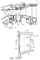
- Figure 1 shows a portion of a gas turbine engine 10 having, among other structures, a combustor 12, a high pressure turbine 14, and a low pressure turbine 16.
- the combustor 12 includes a generally annular hollow body defining a combustion chamber 18 therein.
- a compressor (not shown) provides compressed air that passes primarily into the combustor 12 to support combustion and partially around the combustor 12 where it is used to cool both the combustor liners and turbomachinery further downstream.
- Fuel is introduced into the forward end of the combustor 12 and is mixed with the air in a conventional fashion.
- the resulting fuel-air mixture flows into the combustion chamber 18 where it is ignited for generating hot combustion gases.
- the hot combustion gases are discharged to the high pressure turbine 14 located downstream of the combustor 12 where they are expanded so that energy is extracted.
- the hot gases then flow to the low pressure turbine 16 where they are expanded further.
- the high pressure turbine 14 includes a turbine nozzle 20 and a turbine rotor 22.
- the turbine nozzle 20 includes a plurality of circumferentially spaced vanes 24 (only one shown in Figure 1) that are supported between a number of arcuate outer bands 26 and arcuate inner bands 28.
- the vanes 24, outer bands 26 and inner bands 28 are arranged into a plurality of circumferentially adjoining nozzle segments that collectively form a complete 360° assembly.
- each nozzle segment has two of the vanes 24 disposed between one of the outer bands 26 and one of the inner bands 28.
- the present invention is not limited to nozzle segments having two vanes, as nozzle segments having other numbers of vanes are known.
- the vanes 24 are configured so as to optimally direct the combustion gases to the turbine rotor 22.
- the outer and inner bands 26 and 28 of each nozzle segment define the outer and inner radial boundaries, respectively, of the gas flow through the nozzle 20.
- the turbine rotor 22 includes a plurality of circumferentially spaced apart blades 32 (only one shown in Figure 1) extending radially outwardly from a rotor disk 34 that rotates about the centerline axis of the engine.
- the blades 32 include airfoil portions that extend into the gas flow.
- a plurality of arcuate shrouds 36 is arranged circumferentially in an annular array so as to closely surround the rotor blades 32 and thereby define the outer radial flowpath boundary for the hot combustion gases flowing through the turbine rotor 22.
- the shrouds 36 are stationary members supported by a shroud support 38 that is fastened to the engine outer case in a conventional manner.
- the vane 24 includes a hollow airfoil 40 having a concave, pressure side 42 and a convex, suction side 44 joined together at a leading edge 46 and at a trailing edge 48.
- the airfoil 40 extends lengthwise, or radially, from the inner band 28 to the outer band 26.
- the airfoil 40 includes two internal walls 50,52 that divide the airfoil interior into three radially extending cavities 54,56,58.
- the present invention is not limited to three cavities; fewer or more cavities could be provided.
- the portion of the airfoil that extends chordwise beyond the rearmost cavity 58 is referred to herein as the trailing edge wall 60. Accordingly, the trailing edge 48 is at the rear of the trailing edge wall 60.
- Cooling fluid (ordinarily air bled off from the engine's compressor) is supplied to each of the internal cavities 54,56,58 in a manner well known in the art.
- This cooling fluid passes through film cooling holes 62 formed in the pressure and suction sides 42 and 44 so as to provide fluid communication between the cavities 54,56,58 and selected areas on the outer surface of the airfoil 40.
- the cooling fluid exhausted through the film cooling holes 62 flows along the airfoil outer surface forming a film that cools the outer surface and insulates it from the high temperature combustion gases.
- a radially extending step 64 is formed in the trailing edge wall 60 on the pressure side 42 of the airfoil 40.
- a plurality of cooling slots 66 extend from the rearmost cavity 58 to the step 64, thereby providing fluid communication between the rearmost cavity 58 and the pressure side of the trailing edge wall 60.
- the cooling fluid (represented by arrow A in Figure 3) exhausted through the cooing slots 66 cools the trailing edge wall 60.
- the cooling slots 66 exit at the step 64 because the trailing edge wall 60 is generally too thin to support slots extending all the way to the trailing edge 48.
- a plurality of cooling holes 68 is formed in the trailing edge wall 60.
- the cooling holes 68 extend laterally through the trailing edge wall 60, from the pressure side 42 to the suction side 44.
- the through-wall cooling holes 68 have inlets located on the pressure side 42, downstream, or aft, of the step 64 and the cooling slots 66.
- a portion of the cooling fluid exiting the cooling slots 66 will pass through the through-wall cooling holes 68 (as represented by arrow B in Figure 3) and exit on the suction side of the trailing edge wall 60.
- the through-wall cooling holes 68 reduce temperature gradients and thermal stress in the trailing edge 48.
- the through-wall cooling holes 68 are preferably angled downstream (i.e., toward the trailing edge 48) so that the exiting cooling fluid will flow along the outer surface on the suction side of the trailing edge wall 60.
- the through-wall cooling holes 68 are preferably arranged in a radial or lengthwise row that extends substantially the length of the airfoil 40.
- the through-wall cooling holes 68 can be arranged in multiple lengthwise rows as shown in Figure 5.
- the cooling holes 68 of one row are staggered with respect to the cooling holes 68 of the adjacent row to best distribute the cooling fluid over the trailing edge wall 60.
- the through-wall cooling holes 68 can have almost any shape, including oval (as shown in the Figures), circular, rectangular and so on.
- the present invention provides a turbine airfoil 40 in which cooling of the trailing edge 48 is improved by the addition of an aft, suction side film bleed from the pressure side slot film.
- Aerodynamic studies conclude that introduction of suction side film cooling in the extreme aft portion of the airfoil (as opposed to the region just downstream of the nozzle throat plane) does not significantly reduce engine performance.
- Cooling analysis shows that the addition of this suction side cooling film via the through-wall cooling holes 68 is extremely effective in cooling the trailing edge 48.
- the through-wall cooling holes 68 reduce temperature gradients and thermal stress in the trailing edge 48 as effectively as thermal barrier coatings.
- use of the through-wall cooling holes 68 eliminates the need to use a costly thermal barrier coating.
- the through-wall cooling holes 68 are compatible with thermal barrier coatings. That is, through-wall cooling holes could be used in conjunction with a thermal barrier coating to achieve an even greater level of thermal protection.
Landscapes
- Engineering & Computer Science (AREA)
- Mechanical Engineering (AREA)
- General Engineering & Computer Science (AREA)
- Turbine Rotor Nozzle Sealing (AREA)
Applications Claiming Priority (2)
| Application Number | Priority Date | Filing Date | Title |
|---|---|---|---|
| US457652 | 1999-12-09 | ||
| US09/457,652 US6422819B1 (en) | 1999-12-09 | 1999-12-09 | Cooled airfoil for gas turbine engine and method of making the same |
Publications (3)
| Publication Number | Publication Date |
|---|---|
| EP1106782A2 EP1106782A2 (en) | 2001-06-13 |
| EP1106782A3 EP1106782A3 (en) | 2003-01-15 |
| EP1106782B1 true EP1106782B1 (en) | 2006-04-19 |
Family
ID=23817608
Family Applications (1)
| Application Number | Title | Priority Date | Filing Date |
|---|---|---|---|
| EP00310957A Expired - Lifetime EP1106782B1 (en) | 1999-12-09 | 2000-12-08 | Cooled airfoil for gas turbine engine and method of making the same |
Country Status (6)
| Country | Link |
|---|---|
| US (1) | US6422819B1 (enExample) |
| EP (1) | EP1106782B1 (enExample) |
| JP (1) | JP2001200704A (enExample) |
| BR (1) | BR0005809A (enExample) |
| CA (1) | CA2327203A1 (enExample) |
| DE (1) | DE60027390T2 (enExample) |
Families Citing this family (27)
| Publication number | Priority date | Publication date | Assignee | Title |
|---|---|---|---|---|
| US6325593B1 (en) * | 2000-02-18 | 2001-12-04 | General Electric Company | Ceramic turbine airfoils with cooled trailing edge blocks |
| US6514037B1 (en) * | 2001-09-26 | 2003-02-04 | General Electric Company | Method for reducing cooled turbine element stress and element made thereby |
| US7080971B2 (en) | 2003-03-12 | 2006-07-25 | Florida Turbine Technologies, Inc. | Cooled turbine spar shell blade construction |
| US6932573B2 (en) | 2003-04-30 | 2005-08-23 | Siemens Westinghouse Power Corporation | Turbine blade having a vortex forming cooling system for a trailing edge |
| JP4346412B2 (ja) * | 2003-10-31 | 2009-10-21 | 株式会社東芝 | タービン翼列装置 |
| GB2417295B (en) * | 2004-08-21 | 2006-10-25 | Rolls Royce Plc | A component having a cooling arrangement |
| US7249934B2 (en) * | 2005-08-31 | 2007-07-31 | General Electric Company | Pattern cooled turbine airfoil |
| US7780413B2 (en) * | 2006-08-01 | 2010-08-24 | Siemens Energy, Inc. | Turbine airfoil with near wall inflow chambers |
| US7806650B2 (en) * | 2006-08-29 | 2010-10-05 | General Electric Company | Method and apparatus for fabricating a nozzle segment for use with turbine engines |
| DE102006042647A1 (de) * | 2006-09-12 | 2008-03-27 | Mtu Aero Engines Gmbh | Turbine einer Gasturbine |
| US7766615B2 (en) * | 2007-02-21 | 2010-08-03 | United Technlogies Corporation | Local indented trailing edge heat transfer devices |
| US7836703B2 (en) * | 2007-06-20 | 2010-11-23 | General Electric Company | Reciprocal cooled turbine nozzle |
| EP2255072B1 (de) * | 2008-03-28 | 2015-05-06 | Alstom Technology Ltd | Leitschaufel für eine gasturbine sowie gasturbine mit einer solchen leitschaufel |
| US20090293495A1 (en) * | 2008-05-29 | 2009-12-03 | General Electric Company | Turbine airfoil with metered cooling cavity |
| US7980821B1 (en) * | 2008-12-15 | 2011-07-19 | Florida Turbine Technologies, Inc. | Turbine blade with trailing edge cooling |
| GB2467791B (en) * | 2009-02-16 | 2011-06-01 | Rolls Royce Plc | Vane |
| US9422816B2 (en) * | 2009-06-26 | 2016-08-23 | United Technologies Corporation | Airfoil with hybrid drilled and cutback trailing edge |
| EP2418357A1 (en) | 2010-08-05 | 2012-02-15 | Siemens Aktiengesellschaft | Turbine airfoil and method for thermal barrier coating |
| US8585350B1 (en) * | 2011-01-13 | 2013-11-19 | George Liang | Turbine vane with trailing edge extension |
| JP5387751B2 (ja) * | 2012-11-05 | 2014-01-15 | 株式会社Ihi | タービン翼 |
| JP6038620B2 (ja) * | 2012-12-05 | 2016-12-07 | 三菱日立パワーシステムズ株式会社 | ガスタービン冷却翼およびガスタービン冷却翼の補修方法 |
| US9790801B2 (en) | 2012-12-27 | 2017-10-17 | United Technologies Corporation | Gas turbine engine component having suction side cutback opening |
| WO2015012918A2 (en) * | 2013-06-04 | 2015-01-29 | United Technologies Corporation | Gas turbine engine airfoil trailing edge suction side cooling |
| US11280214B2 (en) * | 2014-10-20 | 2022-03-22 | Raytheon Technologies Corporation | Gas turbine engine component |
| US10641113B2 (en) * | 2015-04-08 | 2020-05-05 | United Technologies Corporation | Airfoils |
| US10344598B2 (en) * | 2015-12-03 | 2019-07-09 | General Electric Company | Trailing edge cooling for a turbine blade |
| US11519277B2 (en) | 2021-04-15 | 2022-12-06 | General Electric Company | Component with cooling passage for a turbine engine |
Family Cites Families (18)
| Publication number | Priority date | Publication date | Assignee | Title |
|---|---|---|---|---|
| US3515499A (en) * | 1968-04-22 | 1970-06-02 | Aerojet General Co | Blades and blade assemblies for turbine engines,compressors and the like |
| GB1560683A (en) * | 1972-11-28 | 1980-02-06 | Rolls Royce | Turbine blade |
| US4153386A (en) * | 1974-12-11 | 1979-05-08 | United Technologies Corporation | Air cooled turbine vanes |
| JPS59107903U (ja) * | 1983-01-12 | 1984-07-20 | 株式会社日立製作所 | 後縁吹出し冷却翼 |
| JPS6298701U (enExample) * | 1985-12-13 | 1987-06-23 | ||
| JPH03123903U (enExample) * | 1990-03-30 | 1991-12-17 | ||
| US5281084A (en) | 1990-07-13 | 1994-01-25 | General Electric Company | Curved film cooling holes for gas turbine engine vanes |
| JPH0514502U (ja) * | 1991-08-05 | 1993-02-26 | 株式会社日立製作所 | ガスタービン冷却翼 |
| US5259730A (en) | 1991-11-04 | 1993-11-09 | General Electric Company | Impingement cooled airfoil with bonding foil insert |
| US5288207A (en) * | 1992-11-24 | 1994-02-22 | United Technologies Corporation | Internally cooled turbine airfoil |
| US5375972A (en) * | 1993-09-16 | 1994-12-27 | The United States Of America As Represented By The Secretary Of The Air Force | Turbine stator vane structure |
| US5516260A (en) | 1994-10-07 | 1996-05-14 | General Electric Company | Bonded turbine airfuel with floating wall cooling insert |
| FR2743391B1 (fr) * | 1996-01-04 | 1998-02-06 | Snecma | Aube refrigeree de distributeur de turbine |
| US5630700A (en) | 1996-04-26 | 1997-05-20 | General Electric Company | Floating vane turbine nozzle |
| JP3781832B2 (ja) * | 1996-08-29 | 2006-05-31 | 株式会社東芝 | ガスタービン |
| US6126397A (en) * | 1998-12-22 | 2000-10-03 | United Technologies Corporation | Trailing edge cooling apparatus for a gas turbine airfoil |
| US6102658A (en) * | 1998-12-22 | 2000-08-15 | United Technologies Corporation | Trailing edge cooling apparatus for a gas turbine airfoil |
| US6179565B1 (en) * | 1999-08-09 | 2001-01-30 | United Technologies Corporation | Coolable airfoil structure |
-
1999
- 1999-12-09 US US09/457,652 patent/US6422819B1/en not_active Expired - Fee Related
-
2000
- 2000-11-30 CA CA002327203A patent/CA2327203A1/en not_active Abandoned
- 2000-12-08 BR BR0005809-2A patent/BR0005809A/pt not_active Application Discontinuation
- 2000-12-08 EP EP00310957A patent/EP1106782B1/en not_active Expired - Lifetime
- 2000-12-08 DE DE60027390T patent/DE60027390T2/de not_active Expired - Lifetime
- 2000-12-08 JP JP2000373651A patent/JP2001200704A/ja active Pending
Also Published As
| Publication number | Publication date |
|---|---|
| EP1106782A3 (en) | 2003-01-15 |
| JP2001200704A (ja) | 2001-07-27 |
| DE60027390T2 (de) | 2007-03-29 |
| DE60027390D1 (de) | 2006-05-24 |
| US6422819B1 (en) | 2002-07-23 |
| CA2327203A1 (en) | 2001-06-09 |
| EP1106782A2 (en) | 2001-06-13 |
| BR0005809A (pt) | 2001-07-17 |
Similar Documents
| Publication | Publication Date | Title |
|---|---|---|
| EP1106782B1 (en) | Cooled airfoil for gas turbine engine and method of making the same | |
| EP1205634B1 (en) | Turbine blade and use thereof | |
| EP1205636B1 (en) | Turbine blade for a gas turbine and method of cooling said blade | |
| US8172533B2 (en) | Turbine blade internal cooling configuration | |
| US8177507B2 (en) | Triangular serpentine cooling channels | |
| JP4659206B2 (ja) | 勾配付きフイルム冷却を備えるタービンノズル | |
| US6554563B2 (en) | Tangential flow baffle | |
| CN106545365B (zh) | 喷嘴节段、喷嘴组件和燃气涡轮发动机 | |
| US6609884B2 (en) | Cooling of gas turbine engine aerofoils | |
| US7094027B2 (en) | Row of long and short chord length and high and low temperature capability turbine airfoils | |
| US6227798B1 (en) | Turbine nozzle segment band cooling | |
| EP2055898B1 (en) | Gas turbine engine with circumferential array of airfoils with platform cooling | |
| EP2105580B1 (en) | Hybrid impingement cooled turbine nozzle | |
| US20190085705A1 (en) | Component for a turbine engine with a film-hole | |
| US20090293495A1 (en) | Turbine airfoil with metered cooling cavity | |
| EP1288436A2 (en) | Turbine airfoil for gas turbine engine | |
| US20190264569A1 (en) | Turbine rotor blade with exiting hole to deliver fluid to boundary layer film | |
| EP2631431B1 (en) | Aerofoil cooling arrangement | |
| US20020031429A1 (en) | Gas turbine engine system | |
| GB2279705A (en) | Cooling of turbine blades of a gas turbine engine | |
| GB2366600A (en) | Cooling arrangement for trailing edge of aerofoil |
Legal Events
| Date | Code | Title | Description |
|---|---|---|---|
| PUAI | Public reference made under article 153(3) epc to a published international application that has entered the european phase |
Free format text: ORIGINAL CODE: 0009012 |
|
| AK | Designated contracting states |
Kind code of ref document: A2 Designated state(s): AT BE CH CY DE DK ES FI FR GB GR IE IT LI LU MC NL PT SE TR |
|
| AX | Request for extension of the european patent |
Free format text: AL;LT;LV;MK;RO;SI |
|
| PUAL | Search report despatched |
Free format text: ORIGINAL CODE: 0009013 |
|
| AK | Designated contracting states |
Kind code of ref document: A3 Designated state(s): AT BE CH CY DE DK ES FI FR GB GR IE IT LI LU MC NL PT SE TR |
|
| AX | Request for extension of the european patent |
Free format text: AL;LT;LV;MK;RO;SI |
|
| 17P | Request for examination filed |
Effective date: 20030715 |
|
| AKX | Designation fees paid |
Designated state(s): DE FR GB IT |
|
| 17Q | First examination report despatched |
Effective date: 20031017 |
|
| GRAP | Despatch of communication of intention to grant a patent |
Free format text: ORIGINAL CODE: EPIDOSNIGR1 |
|
| GRAS | Grant fee paid |
Free format text: ORIGINAL CODE: EPIDOSNIGR3 |
|
| GRAA | (expected) grant |
Free format text: ORIGINAL CODE: 0009210 |
|
| AK | Designated contracting states |
Kind code of ref document: B1 Designated state(s): DE FR GB IT |
|
| REG | Reference to a national code |
Ref country code: GB Ref legal event code: FG4D |
|
| REF | Corresponds to: |
Ref document number: 60027390 Country of ref document: DE Date of ref document: 20060524 Kind code of ref document: P |
|
| ET | Fr: translation filed | ||
| PLBE | No opposition filed within time limit |
Free format text: ORIGINAL CODE: 0009261 |
|
| STAA | Information on the status of an ep patent application or granted ep patent |
Free format text: STATUS: NO OPPOSITION FILED WITHIN TIME LIMIT |
|
| 26N | No opposition filed |
Effective date: 20070122 |
|
| PGFP | Annual fee paid to national office [announced via postgrant information from national office to epo] |
Ref country code: FR Payment date: 20100106 Year of fee payment: 10 Ref country code: GB Payment date: 20091229 Year of fee payment: 10 |
|
| PGFP | Annual fee paid to national office [announced via postgrant information from national office to epo] |
Ref country code: IT Payment date: 20091229 Year of fee payment: 10 |
|
| PGFP | Annual fee paid to national office [announced via postgrant information from national office to epo] |
Ref country code: DE Payment date: 20091230 Year of fee payment: 10 |
|
| GBPC | Gb: european patent ceased through non-payment of renewal fee |
Effective date: 20101208 |
|
| REG | Reference to a national code |
Ref country code: FR Ref legal event code: ST Effective date: 20110831 |
|
| PG25 | Lapsed in a contracting state [announced via postgrant information from national office to epo] |
Ref country code: FR Free format text: LAPSE BECAUSE OF NON-PAYMENT OF DUE FEES Effective date: 20110103 |
|
| REG | Reference to a national code |
Ref country code: DE Ref legal event code: R119 Ref document number: 60027390 Country of ref document: DE Effective date: 20110701 |
|
| PG25 | Lapsed in a contracting state [announced via postgrant information from national office to epo] |
Ref country code: GB Free format text: LAPSE BECAUSE OF NON-PAYMENT OF DUE FEES Effective date: 20101208 Ref country code: DE Free format text: LAPSE BECAUSE OF NON-PAYMENT OF DUE FEES Effective date: 20110701 |
|
| PG25 | Lapsed in a contracting state [announced via postgrant information from national office to epo] |
Ref country code: IT Free format text: LAPSE BECAUSE OF NON-PAYMENT OF DUE FEES Effective date: 20101208 |