EP1106499B1 - Auftriebskörper - Google Patents
Auftriebskörper Download PDFInfo
- Publication number
- EP1106499B1 EP1106499B1 EP00650203A EP00650203A EP1106499B1 EP 1106499 B1 EP1106499 B1 EP 1106499B1 EP 00650203 A EP00650203 A EP 00650203A EP 00650203 A EP00650203 A EP 00650203A EP 1106499 B1 EP1106499 B1 EP 1106499B1
- Authority
- EP
- European Patent Office
- Prior art keywords
- forming
- closure
- float
- throughbore
- anchorages
- Prior art date
- Legal status (The legal status is an assumption and is not a legal conclusion. Google has not performed a legal analysis and makes no representation as to the accuracy of the status listed.)
- Expired - Lifetime
Links
- 239000000463 material Substances 0.000 claims abstract description 15
- 239000004033 plastic Substances 0.000 claims abstract description 11
- 229920003023 plastic Polymers 0.000 claims abstract description 11
- 238000000034 method Methods 0.000 claims description 32
- 238000004519 manufacturing process Methods 0.000 claims description 7
- 238000000465 moulding Methods 0.000 claims description 6
- 229920001169 thermoplastic Polymers 0.000 claims description 5
- 239000004416 thermosoftening plastic Substances 0.000 claims description 5
- -1 polyethylene Polymers 0.000 claims description 3
- 239000004698 Polyethylene Substances 0.000 claims description 2
- 229920000573 polyethylene Polymers 0.000 claims description 2
- 239000002991 molded plastic Substances 0.000 abstract 1
- 238000010276 construction Methods 0.000 description 5
- XLYOFNOQVPJJNP-UHFFFAOYSA-N water Substances O XLYOFNOQVPJJNP-UHFFFAOYSA-N 0.000 description 4
- 241000237536 Mytilus edulis Species 0.000 description 2
- 238000003780 insertion Methods 0.000 description 2
- 230000037431 insertion Effects 0.000 description 2
- 235000020638 mussel Nutrition 0.000 description 2
- 238000009372 pisciculture Methods 0.000 description 2
- 241000251468 Actinopterygii Species 0.000 description 1
- 239000004743 Polypropylene Substances 0.000 description 1
- 239000000853 adhesive Substances 0.000 description 1
- 230000001070 adhesive effect Effects 0.000 description 1
- 238000000071 blow moulding Methods 0.000 description 1
- 238000009750 centrifugal casting Methods 0.000 description 1
- 230000002950 deficient Effects 0.000 description 1
- 238000005553 drilling Methods 0.000 description 1
- 238000009313 farming Methods 0.000 description 1
- 230000007257 malfunction Effects 0.000 description 1
- 239000000289 melt material Substances 0.000 description 1
- 229920001155 polypropylene Polymers 0.000 description 1
- 238000009877 rendering Methods 0.000 description 1
- 239000003643 water by type Substances 0.000 description 1
Images


Classifications
-
- B—PERFORMING OPERATIONS; TRANSPORTING
- B63—SHIPS OR OTHER WATERBORNE VESSELS; RELATED EQUIPMENT
- B63B—SHIPS OR OTHER WATERBORNE VESSELS; EQUIPMENT FOR SHIPPING
- B63B22/00—Buoys
- B63B22/22—Inflatable buoys with gas generating means
-
- A—HUMAN NECESSITIES
- A01—AGRICULTURE; FORESTRY; ANIMAL HUSBANDRY; HUNTING; TRAPPING; FISHING
- A01K—ANIMAL HUSBANDRY; AVICULTURE; APICULTURE; PISCICULTURE; FISHING; REARING OR BREEDING ANIMALS, NOT OTHERWISE PROVIDED FOR; NEW BREEDS OF ANIMALS
- A01K75/00—Accessories for fishing nets; Details of fishing nets, e.g. structure
- A01K75/04—Floats
Definitions
- the present invention relates to a method of manufacturing a buoyancy float of the type comprising an inflatable, elongate, hollow body of a thermoplastics material, the float body terminating adjacent each end in at least a pair of spaced-apart anchorages, wherein the method comprises the initial steps of moulding the hollow body from the hot plastics material and forming a throughbore in one end of the float body.
- buoyancy floats In fishing, nets are often suspended across wide expanses of water out of buoyancy floats until such time as it is desired to gather in the catch.
- buoyancy floats are also used extensively in other marine operations, such as, for example, fish farming, particularly in the farming of bivalves, where the bivalves are suspended from the ropes which in turn are supported by buoyancy floats in the water.
- buoyancy floats carry between them a rope which in turn has suspended therefrom further ropes, or netting.
- floats should support one or more spaced rows of ropes or netting so that for example additional mussels could be reared, or additional nets could be hung one inside the other. This could be particularly important in fish farming where there is a considerable need to ensure that the fish being reared in the waters are not allowed to escape to the open sea or other area from which they are being reared.
- GB-A-847 342 discloses a process for making inflatable buoyancy floats utilizing centrifugal casting.
- buoyancy floats One of the problems with such constructions of buoyancy floats is firstly the difficulty in fitting a valve to the buoyancy float during manufacture and then secondly, during use, replacing defective valves.
- the latter is a particular problem in that the conditions under which the valves operate are often quite severe and the valves are subject to relatively frequent malfunction. Very often, when it is required to re-flate the buoyancy float after a period of time, the valves are often inoperative.
- a further problem with such valves is that there can be considerable difficulty in fitting them even where adhesives and the like are used.
- the moulding of a plastics article and in particular the moulding of a valve receiving hole within such a buoyancy float is one that does not produce a hole to relatively tight tolerances.
- the present inventions is directed towards providing an improved construction of buoyancy float which will allow a wider range of uses of such floats in marine fishing and other marine cultural operations.
- the present invention is further directed towards overcoming these problems and in particular to providing a method of manufacturing such an inflatable buoyancy float which will allow the fitting of the valve in an efficient and timely manner. Additionally, it is directed towards providing a buoyancy float in which the valve will not be prone to detachment from the buoyancy float body while in use. Still further, the invention is directed towards providing an improved construction of valve for such a buoyancy float and in particular one which will allow easy inflation as well as easy and safe deflation.
- a buoyancy float of the type comprising an inflatable, elongate, hollow body of a thermoplastics material, the float body terminating adjacent each end in at least a pair of spaced-apart anchorages, wherein the method comprises the steps of moulding the hollow body from the hot plastics material, forming a throughbore in one end of the float body, forming a screw thread in the throughbore by inserting a closure having a closure body into the throughbore while the thermoplastics material is warm and malleable, the closure body having a screw thread formed thereon.
- the method comprises the intermediate step of forming a closure-receiving spigot in one end of the float body, the a closure-receiving spigot being proud of the float body, and thereafter forming the throughbore in the closure-receiving spigot (9).
- the step of forming the throughbore in one end of the float body further comprises forming a throughbore having a diameter substantially smaller than the exterior dimensions of the screw-thread formed on the closure body.
- a method comprising the additional step of rotating the closure as it is inserted into the throughbore.
- a method comprising the additional step of allowing the plastics material to set around the screw-thread formed on the closure body.
- a method comprising the intermediate steps of forming a substantially cylindrical body having a pair of end plates and forming an upstanding support on each end plate, each support having through-holes forming the anchorages.
- a method comprising the intermediate steps of forming one support comprising four upstanding in-line pillars bridged by connector plates having three through holes, the outer holes forming the anchorages and the inner hole, a carrying handle, and forming the other support comprising four upstanding in-line pillars, each of the outer pillars bridged by a connector plate within the adjacent pillar, the connector plates having holes forming the anchorages and a closure-receiving spigot formed between the inner pillars.
- the step of forming a screw thread in the throughbore by inserting the closure further comprises inserting a closure having a closure body with a screw thread formed thereon that tapers towards the distal free end of the closure body over portion of its length.
- the step of forming a screw thread in the throughbore by inserting a closure further comprises inserting a one-way valve for inflation of the float, the valve comprising a valve body having a gas inlet and a gas outlet and a non-return valve mechanism in the valve body.
- valve mounts a blanking closure in its gas inlet. This is a safety precaution to prevent the leaking of buoyancy gas inserted into the float which buoyancy gas would generally be air.
- the float is manufactured from polyethylene.
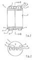
- a buoyancy float indicated generally by the reference numeral 1, comprising an elongate cylindrical body member 2 having a pair of spaced-apart end plates 3 and 4.
- a support formed from four upstanding radially arranged pillars 5 bridged by connector plates 6 having through-holes forming two anchorages 7 and a hole forming a handle 8.
- the end plate 4 carries another four pillars 5 with connector plates 6 between the outermost pillar supports 5, again having a pair of through-holes forming anchorage holes 7.
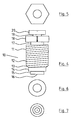
- a threaded spigot 9 is used for mounting either a closure, not shown, or a valve mounting such as, for example, a one-way valve.
- a closure 10 formed by a non-return valve which comprises a valve body 11 having screw threads 12 tapering at its distal free end 13 and terminating in a cylindrical portion 14 mounting a non-return valve mechanism 15 such as sold under the Trade Mark VENTREX which forms a gas outlet 16.
- the proximal end of the valve body 11 carries an undercut O-ring receiving groove 17 and a hexagonal head 18 forming a gas inlet 19 within which is mounted a set screw forming a blanking closure 20, the set screw normally mounts a rubber o-ring seal, which seal is not shown on the drawing.
- the buoyancy float 1 is moulded including the spigot 9 which incorporates a hole relatively small compared to the valve body 11. While the moulding is still warm and the plastics material malleable, the cylindrical portion 14 of the closure 10 is inserted into the spigot 9 and rotated until the threads firmly lock the closure 10 against the spigot 9. O-rings are preferably mounted in the groove 17 before insertion of the closure 10.
- float 1 in the sea, the upper surface of which is identified by the reference numeral 25.
- the float 1 carries two ropes 26 and 27, which ropes are connected at their extremities to other floats 1, or to, for example, a permanent anchorage such as a quay wall, or indeed a vessel all of which is not illustrated.
- the two ropes 26 and 27 are spaced apart and thus can be used to, for example, hang other ropes for the growing of mussels, netting and the like.
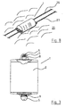
- Fig. 9 shows an alternative construction in which there are upper ropes 28 and 29 again spaced apart and lower ropes 30 and 31, again spaced apart. It will be appreciated that the float 1 is now lying vertically in the water.
- Fig. 10 illustrates the float 1 again lying horizontally in the water, but in this case it supports two spaced apart ropes 26 and 27 which will be spaced apart the distance between the ends of the float.
- each rope is connected to two anchorages but they are now on the one end plate. This, will give the maximum spacing between the ropes 26 and 27, which may be desired in certain circumstances.
- Fig. 11 there is illustrated an alternative arrangement which is particularly suitable for use in heavy seas.
- a plurality of floats 1 mounted between a rope 35 which is anchored at both ends, the anchorage of which is not shown.
- a fishing net 37 Suspended from the central handle 8 by ropes 36 of approximately 2 meters in length is a fishing net 37.
- the handle 8 is actually the anchorage for the ropes 36.
- the anchorages 7 on the end plate 3 could be used.
- Blow moulding is very suitable for manufacturing the floats according to the invention.
- Polypropylene is a particularly suitable plastics material.
Landscapes
- Life Sciences & Earth Sciences (AREA)
- Environmental Sciences (AREA)
- Mechanical Engineering (AREA)
- Chemical & Material Sciences (AREA)
- Ocean & Marine Engineering (AREA)
- Combustion & Propulsion (AREA)
- Marine Sciences & Fisheries (AREA)
- Animal Husbandry (AREA)
- Biodiversity & Conservation Biology (AREA)
- Engineering & Computer Science (AREA)
- Farming Of Fish And Shellfish (AREA)
- Blow-Moulding Or Thermoforming Of Plastics Or The Like (AREA)
- Check Valves (AREA)
- Devices For Conveying Motion By Means Of Endless Flexible Members (AREA)
- Sanitary Device For Flush Toilet (AREA)
Claims (13)
- Verfahren zum Herstellen eines Auftriebsschwimmers (1) des Typs, der einen aufblasbaren, länglichen, hohlen Körper (2) aus einem Thermoplastmaterial umfasst, wobei der Schwimmerkörper (2) angrenzend an jedes Ende jeweils in mindestens einem Paar beabstandeter Verankerungen (7) endet, wobei das Verfahren folgende Schritte umfasst:Formen des hohlen Körpers (2) aus dem heißen Kunststoffmaterial,Bilden einer Durchgangsbohrung in einem Ende des Schwimmerkörpers (2),dadurch gekennzeichnet, dass das Verfahren weiter folgenden Schritt umfasst:Bilden eines Schraubengewindes in der Durchgangsbohrung durch Einführen eines Verschlusses (10) mit einem Verschlusskörper (11) in die Durchgangsbohrung während das Thermoplastmaterial warm und umformbar ist, wobei am Verschlusskörper (11) ein Schraubengewinde (12) geformt ist.
- Verfahren nach Anspruch 1, wobei das Verfahren folgenden Zwischenschritt umfasst:Bilden eines den Verschluss aufnehmenden Zapfens (9) in einem Ende des Schwimmerkörpers (2), wobei der den Verschluss aufnehmende Zapfen (9) über dem Schwimmerkörper (2) vorsteht,und danach Bilden der Durchgangsbohrung in dem den Verschluss aufnehmenden Zapfen (9).
- Verfahren nach Anspruch 1 oder 2, wobei der Schritt des Bildens der Durchgangsbohrung in einem Ende des Schwimmerkörpers weiter das Bilden einer Durchgangsbohrung umfasst, die einen Durchmesser hat, der wesentlich kleiner ist als die Außenabmessungen des am Verschlusskörper (11) gebildeten Schraubengewindes (12).
- Verfahren nach einem der vorangehenden Ansprüche, wobei das Verfahren den zusätzlichen Schritt des Drehens des Verschlusses (10) umfasst, wenn er in die Durchgangsbohrung eingeführt wird.
- Verfahren nach einem der vorangehenden Ansprüche, wobei das Verfahren den zusätzlichen Schritt des Erhärtenlassens des Kunststoffmaterials um das am Verschlusskörper (11) gebildete Schraubengewinde (12) umfasst.
- Verfahren nach Anspruch 1, wobei das Verfahren folgende Zwischenschritte umfasst:Bilden eines im Wesentlichen zylindrischen Körpers (2) mit einem Paar Stirnplatten (3, 4) undBilden eines aufrechten Trägers an jeder Stirnplatte, wobei jeder Träger durchgehende Öffnungen hat, die die Verankerungen (7) bilden.
- Verfahren nach Anspruch 2, wobei das Verfahren folgende Zwischenschritte umfasst:Bilden eines im Wesentlichen zylindrischen Körpers (2) mit einem Paar Stirnplatten (3, 4) undBilden eines aufrechten Trägers an jeder Stirnplatte, wobei jeder Träger durchgehende Öffnungen hat, die die Verankerungen (7) bilden.
- Verfahren nach Anspruch 6, wobei das Verfahren folgende Zwischenschritte umfasst:Bilden eines Trägers umfassend vier aufrechte in einer Reihe angeordnete Pfosten (15), die durch Verbindungsplatten (6) mit drei durchgehenden Öffnungen überbrückt werden, wobei die äußeren Öffnungen die Verankerungen (7) bilden und die innere Öffnung einen Traggriff (8) bildet, undBilden des anderen Trägers umfassend vier aufrechte, in einer Reihe angeordnete Pfosten (5), wobei die äußeren Pfosten jeweils durch eine Verbindungsplatte (6) im benachbarten Pfosten (5) überbrückt sind, wobei die Verbindungsplatten (6) Öffnungen, die die Verankerungen (7) bilden, haben und ein den Verschluss aufnehmender Zapfen (9) zwischen den inneren Pfosten (5) gebildet ist.
- Verfahren nach Anspruch 7, wobei das Verfahren folgende Zwischenschritte umfasst:Bilden eines Trägers umfassend vier aufrechte in einer Reihe angeordnete Pfosten (15), die durch Verbindungsplatten (6) mit drei durchgehenden Öffnungen überbrückt werden, wobei die äußeren Öffnungen die Verankerungen (7) bilden und die innere Öffnung einen Traggriff (8) bildet, undBilden des anderen Trägers umfassend vier aufrechte, in einer Reihe angeordnete Pfosten (5), wobei die äußeren Pfosten jeweils durch eine Verbindungsplatte (6) im benachbarten Pfosten (5) überbrückt sind, wobei die Verbindungsplatten (6) Öffnungen, die die Verankerungen (7) bilden haben und der den Verschluss aufnehmende Zapfen (9) zwischen den inneren Pfosten (5) gebildet ist.
- Verfahren nach einem der vorangehenden Ansprüche, wobei der Schritt des Bildens eines Schraubengewindes in der Durchgangsbohrung durch Einführen des Verschlusses (10) weiter das Einführen eines Verschlusses (10) umfasst, der einen Verschlusskörper (11) mit einem daran gebildeten Schraubengewinde (12) hat, der über einen Abschnitt seiner Länge zum distalen freien Ende (13) des Verschlusskörpers verjüngt ist.
- Verfahren nach einem der vorangehenden Ansprüche, wobei der Schritt des Bildens eines Schraubengewindes in der Durchgangsbohrung durch Einführen eines Verschlusses (10) weiter das Einführen eines Einwegeventils zum Aufblasen des Schwimmers umfasst, wobei das Ventil einen Ventilkörper (11) mit einem Gaseinlass (19) und einem Gasauslass (16) und einen Rückschlagventilmechanismus in dem Ventilkörper (11) umfasst.
- Verfahren nach Anspruch 11, wobei das Ventil einen Verschlussstopfen (20) in seinem Gaseinlass (19) hält.
- Verfahren nach einem der vorangehenden Ansprüche, wobei der Auftriebsschwimmer (1) aus Polyethylen hergestellt wird.
Applications Claiming Priority (4)
| Application Number | Priority Date | Filing Date | Title |
|---|---|---|---|
| IE991029 | 1999-12-08 | ||
| IE991029 | 1999-12-08 | ||
| IE20000780 | 2000-09-28 | ||
| IE000780 | 2000-09-28 |
Publications (3)
| Publication Number | Publication Date |
|---|---|
| EP1106499A2 EP1106499A2 (de) | 2001-06-13 |
| EP1106499A3 EP1106499A3 (de) | 2002-11-27 |
| EP1106499B1 true EP1106499B1 (de) | 2008-11-12 |
Family
ID=26320268
Family Applications (1)
| Application Number | Title | Priority Date | Filing Date |
|---|---|---|---|
| EP00650203A Expired - Lifetime EP1106499B1 (de) | 1999-12-08 | 2000-11-30 | Auftriebskörper |
Country Status (4)
| Country | Link |
|---|---|
| EP (1) | EP1106499B1 (de) |
| AT (1) | ATE414009T1 (de) |
| DE (1) | DE60040779D1 (de) |
| IE (2) | IES20000978A2 (de) |
Cited By (1)
| Publication number | Priority date | Publication date | Assignee | Title |
|---|---|---|---|---|
| WO2014139544A1 (en) | 2013-03-15 | 2014-09-18 | William Alec Milligan | A buoyancy float manufacturing process |
Families Citing this family (2)
| Publication number | Priority date | Publication date | Assignee | Title |
|---|---|---|---|---|
| WO2014209137A2 (en) * | 2013-06-27 | 2014-12-31 | Ventura Marine Limited | A float |
| CA3005644C (en) | 2015-12-08 | 2025-02-06 | Norman Boyle | OSTREIC CULTURE APPARATUS AND METHODS |
Family Cites Families (8)
| Publication number | Priority date | Publication date | Assignee | Title |
|---|---|---|---|---|
| BE524642A (de) * | ||||
| FR619713A (fr) * | 1926-07-31 | 1927-04-07 | Perfectionnements aux flotteurs pneumatiques, chambres de flottaison et autres similaires pour pêche en pleine mer | |
| GB289641A (en) * | 1927-05-06 | 1928-05-03 | John Young | Improvements in pneumatic floats for fishing nets and like purposes |
| GB602405A (en) * | 1945-10-15 | 1948-05-26 | Frederick Roland Lloyd | Improvements in or relating to the manufacture of sheet metal floats for fishing nets and for like purposes |
| NL107733C (de) * | 1957-12-10 | |||
| FR1266606A (fr) * | 1960-06-02 | 1961-07-17 | Electricite De France | Flotteur d'allègement, en particulier pour la pose de conduites sous-marines |
| JPH09117237A (ja) * | 1995-10-26 | 1997-05-06 | Zen Suisan Kk | 浮子及びそれを用いた生簀装置 |
| US5921418A (en) * | 1997-09-08 | 1999-07-13 | Pugh; Gary L. | Valve cap for two liter bottle |
-
2000
- 2000-11-30 AT AT00650203T patent/ATE414009T1/de not_active IP Right Cessation
- 2000-11-30 DE DE60040779T patent/DE60040779D1/de not_active Expired - Fee Related
- 2000-11-30 EP EP00650203A patent/EP1106499B1/de not_active Expired - Lifetime
- 2000-11-30 IE IE20000978A patent/IES20000978A2/en not_active IP Right Cessation
- 2000-11-30 IE IE20000977A patent/IE20000977A1/en not_active Application Discontinuation
Cited By (2)
| Publication number | Priority date | Publication date | Assignee | Title |
|---|---|---|---|---|
| WO2014139544A1 (en) | 2013-03-15 | 2014-09-18 | William Alec Milligan | A buoyancy float manufacturing process |
| AU2013382377B2 (en) * | 2013-03-15 | 2017-10-12 | William Alec Milligan | A buoyancy float manufacturing process |
Also Published As
| Publication number | Publication date |
|---|---|
| EP1106499A3 (de) | 2002-11-27 |
| IE20000977A1 (en) | 2001-07-11 |
| EP1106499A2 (de) | 2001-06-13 |
| DE60040779D1 (de) | 2008-12-24 |
| ATE414009T1 (de) | 2008-11-15 |
| IES20000978A2 (en) | 2002-08-21 |
Similar Documents
| Publication | Publication Date | Title |
|---|---|---|
| US9392774B2 (en) | Containment pens for finfish aquaculture | |
| US6044798A (en) | Floating aquaculture apparatus | |
| US4380213A (en) | Rotatable fish cage | |
| US4465399A (en) | Artificial reef assembly construction and a method | |
| NO334669B1 (no) | Flyteelement og framgangsmåte for å tildanne et oppdriftssystem | |
| IE903087A1 (en) | Buoy for attachment to the net line of a fishing net | |
| AU2021273553B2 (en) | Removeable aquatic basket and float system and method | |
| KR20200102254A (ko) | 공기출입이 가능한 부표 | |
| EP1106499B1 (de) | Auftriebskörper | |
| EP3422844B1 (de) | Auftriebssystem für ein fischbecken | |
| KR200446214Y1 (ko) | 내장형 노즐삽입부를 갖는 해태양식 및 어구용 부표 | |
| KR20060054683A (ko) | 수중 가두리 시설 | |
| KR20050008554A (ko) | 패류용 가두리 시설 | |
| KR200179400Y1 (ko) | 두족류 포획을 위한 어구 | |
| CA3012933C (en) | A shellfish farm | |
| KR20090003595U (ko) | 어구의 부구 | |
| JP2007000039A (ja) | 牡蠣筏 | |
| KR200374986Y1 (ko) | 수중 가두리 시설 | |
| KR100310702B1 (ko) | 해상 구조물 | |
| AU593168B2 (en) | Oyster cultivating equipment and method | |
| DE19928792A1 (de) | Schlauchboot, insbesondere Rettungsinsel | |
| KR100643778B1 (ko) | 저서어류용 가두리 시설 | |
| US20250304216A1 (en) | Automatic Submersible Water Sports Course System | |
| KR200154264Y1 (ko) | 낚시용 구멍찌와 수중찌 및 봉돌 | |
| KR200375141Y1 (ko) | 저서어류용 가두리 시설 |
Legal Events
| Date | Code | Title | Description |
|---|---|---|---|
| PUAI | Public reference made under article 153(3) epc to a published international application that has entered the european phase |
Free format text: ORIGINAL CODE: 0009012 |
|
| AK | Designated contracting states |
Kind code of ref document: A2 Designated state(s): AT BE CH CY DE DK ES FI FR GB GR IE IT LI LU MC NL PT SE TR |
|
| AX | Request for extension of the european patent |
Free format text: AL;LT;LV;MK;RO;SI |
|
| RIC1 | Information provided on ipc code assigned before grant |
Free format text: 7B 63B 22/22 A, 7A 01K 75/04 B, 7B 63B 5/24 B, 7B 29C 39/10 B |
|
| PUAL | Search report despatched |
Free format text: ORIGINAL CODE: 0009013 |
|
| RIC1 | Information provided on ipc code assigned before grant |
Free format text: 7B 63B 22/22 A, 7A 01K 75/04 B, 7B 63B 5/24 B, 7B 29C 39/10 B, 7B 29C 65/66 B |
|
| AK | Designated contracting states |
Kind code of ref document: A3 Designated state(s): AT BE CH CY DE DK ES FI FR GB GR IE IT LI LU MC NL PT SE TR |
|
| AX | Request for extension of the european patent |
Free format text: AL;LT;LV;MK;RO;SI |
|
| 17P | Request for examination filed |
Effective date: 20030508 |
|
| AKX | Designation fees paid |
Designated state(s): AT BE CH CY DE DK ES FI FR GB GR IE IT LI LU MC NL PT SE TR |
|
| 17Q | First examination report despatched |
Effective date: 20040304 |
|
| 17Q | First examination report despatched |
Effective date: 20040304 |
|
| GRAP | Despatch of communication of intention to grant a patent |
Free format text: ORIGINAL CODE: EPIDOSNIGR1 |
|
| GRAS | Grant fee paid |
Free format text: ORIGINAL CODE: EPIDOSNIGR3 |
|
| GRAA | (expected) grant |
Free format text: ORIGINAL CODE: 0009210 |
|
| AK | Designated contracting states |
Kind code of ref document: B1 Designated state(s): AT BE CH CY DE DK ES FI FR GB GR IE IT LI LU MC NL PT SE TR |
|
| REG | Reference to a national code |
Ref country code: GB Ref legal event code: FG4D |
|
| REG | Reference to a national code |
Ref country code: CH Ref legal event code: EP |
|
| REG | Reference to a national code |
Ref country code: IE Ref legal event code: FG4D |
|
| REF | Corresponds to: |
Ref document number: 60040779 Country of ref document: DE Date of ref document: 20081224 Kind code of ref document: P |
|
| PG25 | Lapsed in a contracting state [announced via postgrant information from national office to epo] |
Ref country code: ES Free format text: LAPSE BECAUSE OF FAILURE TO SUBMIT A TRANSLATION OF THE DESCRIPTION OR TO PAY THE FEE WITHIN THE PRESCRIBED TIME-LIMIT Effective date: 20090223 Ref country code: AT Free format text: LAPSE BECAUSE OF FAILURE TO SUBMIT A TRANSLATION OF THE DESCRIPTION OR TO PAY THE FEE WITHIN THE PRESCRIBED TIME-LIMIT Effective date: 20081112 |
|
| PG25 | Lapsed in a contracting state [announced via postgrant information from national office to epo] |
Ref country code: FI Free format text: LAPSE BECAUSE OF FAILURE TO SUBMIT A TRANSLATION OF THE DESCRIPTION OR TO PAY THE FEE WITHIN THE PRESCRIBED TIME-LIMIT Effective date: 20081112 |
|
| PG25 | Lapsed in a contracting state [announced via postgrant information from national office to epo] |
Ref country code: MC Free format text: LAPSE BECAUSE OF NON-PAYMENT OF DUE FEES Effective date: 20081130 |
|
| REG | Reference to a national code |
Ref country code: CH Ref legal event code: PL |
|
| PG25 | Lapsed in a contracting state [announced via postgrant information from national office to epo] |
Ref country code: BE Free format text: LAPSE BECAUSE OF FAILURE TO SUBMIT A TRANSLATION OF THE DESCRIPTION OR TO PAY THE FEE WITHIN THE PRESCRIBED TIME-LIMIT Effective date: 20081112 Ref country code: DK Free format text: LAPSE BECAUSE OF FAILURE TO SUBMIT A TRANSLATION OF THE DESCRIPTION OR TO PAY THE FEE WITHIN THE PRESCRIBED TIME-LIMIT Effective date: 20081112 |
|
| PG25 | Lapsed in a contracting state [announced via postgrant information from national office to epo] |
Ref country code: PT Free format text: LAPSE BECAUSE OF FAILURE TO SUBMIT A TRANSLATION OF THE DESCRIPTION OR TO PAY THE FEE WITHIN THE PRESCRIBED TIME-LIMIT Effective date: 20090413 Ref country code: SE Free format text: LAPSE BECAUSE OF FAILURE TO SUBMIT A TRANSLATION OF THE DESCRIPTION OR TO PAY THE FEE WITHIN THE PRESCRIBED TIME-LIMIT Effective date: 20090212 |
|
| PLBE | No opposition filed within time limit |
Free format text: ORIGINAL CODE: 0009261 |
|
| STAA | Information on the status of an ep patent application or granted ep patent |
Free format text: STATUS: NO OPPOSITION FILED WITHIN TIME LIMIT |
|
| 26N | No opposition filed |
Effective date: 20090813 |
|
| PG25 | Lapsed in a contracting state [announced via postgrant information from national office to epo] |
Ref country code: CH Free format text: LAPSE BECAUSE OF NON-PAYMENT OF DUE FEES Effective date: 20081130 Ref country code: DE Free format text: LAPSE BECAUSE OF NON-PAYMENT OF DUE FEES Effective date: 20090603 Ref country code: LI Free format text: LAPSE BECAUSE OF NON-PAYMENT OF DUE FEES Effective date: 20081130 |
|
| PG25 | Lapsed in a contracting state [announced via postgrant information from national office to epo] |
Ref country code: LU Free format text: LAPSE BECAUSE OF NON-PAYMENT OF DUE FEES Effective date: 20081130 |
|
| PG25 | Lapsed in a contracting state [announced via postgrant information from national office to epo] |
Ref country code: CY Free format text: LAPSE BECAUSE OF FAILURE TO SUBMIT A TRANSLATION OF THE DESCRIPTION OR TO PAY THE FEE WITHIN THE PRESCRIBED TIME-LIMIT Effective date: 20081112 |
|
| PG25 | Lapsed in a contracting state [announced via postgrant information from national office to epo] |
Ref country code: TR Free format text: LAPSE BECAUSE OF FAILURE TO SUBMIT A TRANSLATION OF THE DESCRIPTION OR TO PAY THE FEE WITHIN THE PRESCRIBED TIME-LIMIT Effective date: 20081112 |
|
| PG25 | Lapsed in a contracting state [announced via postgrant information from national office to epo] |
Ref country code: GR Free format text: LAPSE BECAUSE OF FAILURE TO SUBMIT A TRANSLATION OF THE DESCRIPTION OR TO PAY THE FEE WITHIN THE PRESCRIBED TIME-LIMIT Effective date: 20090213 |
|
| REG | Reference to a national code |
Ref country code: FR Ref legal event code: ST Effective date: 20111209 |
|
| PG25 | Lapsed in a contracting state [announced via postgrant information from national office to epo] |
Ref country code: FR Free format text: LAPSE BECAUSE OF NON-PAYMENT OF DUE FEES Effective date: 20090112 |
|
| PG25 | Lapsed in a contracting state [announced via postgrant information from national office to epo] |
Ref country code: IT Free format text: LAPSE BECAUSE OF FAILURE TO SUBMIT A TRANSLATION OF THE DESCRIPTION OR TO PAY THE FEE WITHIN THE PRESCRIBED TIME-LIMIT Effective date: 20081112 |
|
| PGFP | Annual fee paid to national office [announced via postgrant information from national office to epo] |
Ref country code: NL Payment date: 20191122 Year of fee payment: 20 Ref country code: IE Payment date: 20191112 Year of fee payment: 20 |
|
| PGFP | Annual fee paid to national office [announced via postgrant information from national office to epo] |
Ref country code: GB Payment date: 20191128 Year of fee payment: 20 |
|
| REG | Reference to a national code |
Ref country code: NL Ref legal event code: MK Effective date: 20201129 |
|
| REG | Reference to a national code |
Ref country code: GB Ref legal event code: PE20 Expiry date: 20201129 Ref country code: IE Ref legal event code: MK9A |
|
| PG25 | Lapsed in a contracting state [announced via postgrant information from national office to epo] |
Ref country code: IE Free format text: LAPSE BECAUSE OF EXPIRATION OF PROTECTION Effective date: 20201130 Ref country code: GB Free format text: LAPSE BECAUSE OF EXPIRATION OF PROTECTION Effective date: 20201129 |